EP1550845B1 - Détecteur de position - Google Patents
Détecteur de position Download PDFInfo
- Publication number
- EP1550845B1 EP1550845B1 EP04030527A EP04030527A EP1550845B1 EP 1550845 B1 EP1550845 B1 EP 1550845B1 EP 04030527 A EP04030527 A EP 04030527A EP 04030527 A EP04030527 A EP 04030527A EP 1550845 B1 EP1550845 B1 EP 1550845B1
- Authority
- EP
- European Patent Office
- Prior art keywords
- circuit
- counting
- position detector
- detector according
- memory
- Prior art date
- Legal status (The legal status is an assumption and is not a legal conclusion. Google has not performed a legal analysis and makes no representation as to the accuracy of the status listed.)
- Expired - Lifetime
Links
Images

Classifications
-
- G—PHYSICS
- G01—MEASURING; TESTING
- G01D—MEASURING NOT SPECIALLY ADAPTED FOR A SPECIFIC VARIABLE; ARRANGEMENTS FOR MEASURING TWO OR MORE VARIABLES NOT COVERED IN A SINGLE OTHER SUBCLASS; TARIFF METERING APPARATUS; MEASURING OR TESTING NOT OTHERWISE PROVIDED FOR
- G01D5/00—Mechanical means for transferring the output of a sensing member; Means for converting the output of a sensing member to another variable where the form or nature of the sensing member does not constrain the means for converting; Transducers not specially adapted for a specific variable
- G01D5/12—Mechanical means for transferring the output of a sensing member; Means for converting the output of a sensing member to another variable where the form or nature of the sensing member does not constrain the means for converting; Transducers not specially adapted for a specific variable using electric or magnetic means
- G01D5/14—Mechanical means for transferring the output of a sensing member; Means for converting the output of a sensing member to another variable where the form or nature of the sensing member does not constrain the means for converting; Transducers not specially adapted for a specific variable using electric or magnetic means influencing the magnitude of a current or voltage
- G01D5/20—Mechanical means for transferring the output of a sensing member; Means for converting the output of a sensing member to another variable where the form or nature of the sensing member does not constrain the means for converting; Transducers not specially adapted for a specific variable using electric or magnetic means influencing the magnitude of a current or voltage by varying inductance, e.g. by a movable armature
- G01D5/2006—Mechanical means for transferring the output of a sensing member; Means for converting the output of a sensing member to another variable where the form or nature of the sensing member does not constrain the means for converting; Transducers not specially adapted for a specific variable using electric or magnetic means influencing the magnitude of a current or voltage by varying inductance, e.g. by a movable armature by influencing the self-induction of one or more coils
- G01D5/2013—Mechanical means for transferring the output of a sensing member; Means for converting the output of a sensing member to another variable where the form or nature of the sensing member does not constrain the means for converting; Transducers not specially adapted for a specific variable using electric or magnetic means influencing the magnitude of a current or voltage by varying inductance, e.g. by a movable armature by influencing the self-induction of one or more coils by a movable ferromagnetic element, e.g. a core
-
- G—PHYSICS
- G01—MEASURING; TESTING
- G01D—MEASURING NOT SPECIALLY ADAPTED FOR A SPECIFIC VARIABLE; ARRANGEMENTS FOR MEASURING TWO OR MORE VARIABLES NOT COVERED IN A SINGLE OTHER SUBCLASS; TARIFF METERING APPARATUS; MEASURING OR TESTING NOT OTHERWISE PROVIDED FOR
- G01D3/00—Indicating or recording apparatus with provision for the special purposes referred to in the subgroups
- G01D3/08—Indicating or recording apparatus with provision for the special purposes referred to in the subgroups with provision for safeguarding the apparatus, e.g. against abnormal operation, against breakdown
-
- G—PHYSICS
- G01—MEASURING; TESTING
- G01D—MEASURING NOT SPECIALLY ADAPTED FOR A SPECIFIC VARIABLE; ARRANGEMENTS FOR MEASURING TWO OR MORE VARIABLES NOT COVERED IN A SINGLE OTHER SUBCLASS; TARIFF METERING APPARATUS; MEASURING OR TESTING NOT OTHERWISE PROVIDED FOR
- G01D5/00—Mechanical means for transferring the output of a sensing member; Means for converting the output of a sensing member to another variable where the form or nature of the sensing member does not constrain the means for converting; Transducers not specially adapted for a specific variable
- G01D5/12—Mechanical means for transferring the output of a sensing member; Means for converting the output of a sensing member to another variable where the form or nature of the sensing member does not constrain the means for converting; Transducers not specially adapted for a specific variable using electric or magnetic means
- G01D5/14—Mechanical means for transferring the output of a sensing member; Means for converting the output of a sensing member to another variable where the form or nature of the sensing member does not constrain the means for converting; Transducers not specially adapted for a specific variable using electric or magnetic means influencing the magnitude of a current or voltage
- G01D5/20—Mechanical means for transferring the output of a sensing member; Means for converting the output of a sensing member to another variable where the form or nature of the sensing member does not constrain the means for converting; Transducers not specially adapted for a specific variable using electric or magnetic means influencing the magnitude of a current or voltage by varying inductance, e.g. by a movable armature
-
- G—PHYSICS
- G01—MEASURING; TESTING
- G01P—MEASURING LINEAR OR ANGULAR SPEED, ACCELERATION, DECELERATION, OR SHOCK; INDICATING PRESENCE, ABSENCE, OR DIRECTION, OF MOVEMENT
- G01P3/00—Measuring linear or angular speed; Measuring differences of linear or angular speeds
- G01P3/42—Devices characterised by the use of electric or magnetic means
- G01P3/44—Devices characterised by the use of electric or magnetic means for measuring angular speed
- G01P3/48—Devices characterised by the use of electric or magnetic means for measuring angular speed by measuring frequency of generated current or voltage
- G01P3/481—Devices characterised by the use of electric or magnetic means for measuring angular speed by measuring frequency of generated current or voltage of pulse signals
- G01P3/487—Devices characterised by the use of electric or magnetic means for measuring angular speed by measuring frequency of generated current or voltage of pulse signals delivered by rotating magnets
-
- G—PHYSICS
- G01—MEASURING; TESTING
- G01D—MEASURING NOT SPECIALLY ADAPTED FOR A SPECIFIC VARIABLE; ARRANGEMENTS FOR MEASURING TWO OR MORE VARIABLES NOT COVERED IN A SINGLE OTHER SUBCLASS; TARIFF METERING APPARATUS; MEASURING OR TESTING NOT OTHERWISE PROVIDED FOR
- G01D5/00—Mechanical means for transferring the output of a sensing member; Means for converting the output of a sensing member to another variable where the form or nature of the sensing member does not constrain the means for converting; Transducers not specially adapted for a specific variable
- G01D5/12—Mechanical means for transferring the output of a sensing member; Means for converting the output of a sensing member to another variable where the form or nature of the sensing member does not constrain the means for converting; Transducers not specially adapted for a specific variable using electric or magnetic means
- G01D5/25—Selecting one or more conductors or channels from a plurality of conductors or channels, e.g. by closing contacts
- G01D5/251—Selecting one or more conductors or channels from a plurality of conductors or channels, e.g. by closing contacts one conductor or channel
- G01D5/2515—Selecting one or more conductors or channels from a plurality of conductors or channels, e.g. by closing contacts one conductor or channel with magnetically controlled switches, e.g. by movement of a magnet
Definitions
- the invention relates to a position detector for counting acquisition of translational or rotational movements, preferably in a predetermined direction, wherein this position detector is self-sufficient insofar as it can perform at least the required counting and storage operations independently of an external power source.
- US-B1-6,191,687 describes a magnetic revolution counter in which a Wiegandgenerator provides both the pulses to be counted as well as the required for their wireless, each instantaneous transmission to a remote user required energy. A count of the pulses or a buffering of the counts at the location of the sensor does not occur. The problem of a read-write collision is not mentioned.
- US-A-6 084 400 describes a magnetic revolution counter with a plurality of weighing sensors, which can perform both a fine angle measurement within 360 ° and a revolution count, wherein the revolution counts are stored in a non-volatile read-write memory and can be passed by this to a monitoring unit. Again, the possibility of a read-write collision is not mentioned and described no measures to prevent it.
- the invention has the object of providing a position detector of the type mentioned in such a way that a collision of read and write operations on a non-volatile count and memory circuit containing the revolution count is excluded with certainty and_dass he with the lowest possible technical and cost Effort can be realized. In particular, he should have the lowest possible energy consumption and a minimum size.
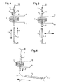
- a first exciter magnet 2 is fastened to a rotating shaft 1 in such a way that the straight line 3 connecting its two magnetic poles extends permanently parallel to the axis of rotation 4. Parallel to this direction is also the longitudinal axis 5 of the sensor wire 6, on which the induction coil 7 is wound, at whose terminals 8 due to the processes described a voltage pulse can always be tapped when the first excitation magnet 2 takes place in the direction of the arrow R rotation the wave 1 in about the in FIG. 1 has reached the position shown and the direction the bias or polarization of the sensor wire 6 (arrow p in Fig.1 ) of the direction of the magnetic field passing through it (arrow P in FIG Fig.1 ) is opposite
- the straight lines 3 and 10 which respectively connect the poles of the first and second excitation magnets 2 and 10 respectively, rotate about the axis of rotation 4 during the rotation of the shaft 1 and thereby constantly move parallel to itself in such a way that they approach each other alternately to a minimum distance to the sensor wire 6 (in FIG. 1 for the first excitation magnet) and thereby generate voltage pulses with alternating signs, in order to then remove from the sensor wire 6 again to a maximum distance (in FIG. 1 shown for the second exciter magnet)
- the magnetic poles of the excitation magnet 2 are oriented opposite to the other position, so that in one of the "reset” of the sensor wire 6 and in the other, the generation of the "actual" count pulse takes place.
- the selection of which of the two occurring at each full revolution, approximately the same amplitude but the opposite sign possessed voltage pulses as a reset pulse and which is to serve as a count is more or less arbitrary and can be determined by the forward direction of a processing electronics belonging halfway rectifier.
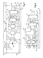
- the IC package 20 includes a comparator circuit 22, a rectifier circuit 24, a voltage limiting circuit 26, a capacitor 28, a control circuit 30, a nonvolatile memory and counting circuit 32, a data read circuit 34, and two diodes 36 and 37.
- the rectifier circuit 24 is characterized by a diode symbol and, in the simplest case, may consist of a single diode which is poled to provide either only negative amplitude voltage pulses or, as in FIG FIG. 7 shown, only voltage pulses with positive amplitude passes.
- a switching transistor with a substantially lower forward voltage is preferably used as the rectifier circuit 24, which is controlled such that it passes voltage pulses of predetermined polarity coming from the induction coil 7, blocks voltage impulses of opposite polarity and, moreover, blocks them Discharging the subsequent capacitor 28 via the induction coil 7 prevented.
- the essential difference from the embodiment described above is that the transfer of the data is not effected in response to a user-initiated interrogation signal which may occur at any given time but by the control circuit 30 'through a line 82 on the line Data reading circuit applied signal is triggered, which is generated with a time offset against the voltage pulses to be counted, that there is no mutual interference between the counting and storage process on the one hand and the reading process on the other.
Landscapes
- Physics & Mathematics (AREA)
- General Physics & Mathematics (AREA)
- Transmission And Conversion Of Sensor Element Output (AREA)
- Measurement Of Length, Angles, Or The Like Using Electric Or Magnetic Means (AREA)
Claims (21)
- Détecteur de position, comprenant les composants suivants pour la saisie par comptage de mouvements de rotation et/ou de translation, préférentiellement dans une direction définissable :au moins un aimant d'excitation (2),un élément ferromagnétique (6) unique, etau moins une bobine d'induction (7) affectée à l'élément ferromagnétique (6),où le mouvement à détecter est représenté par un mouvement relatif entre l'aimant d'excitation (2) et l'élément ferromagnétique (6), et l'énergie prélevée de l'énergie cinétique du mouvement à détecter pendant le rapprochement de ces deux éléments et accumulée au moyen de l'élément ferromagnétique (6) est brusquement libérée lorsqu'une position relative définie et donc une intensité de champ magnétique définie est atteinte, et une impulsion de tension est générée par variation subite du flux magnétique dans la bobine d'induction (7),et, comme équipement électronique,au moins un circuit redresseur (24) pour le redressement d'impulsions de tension de la bobine d'induction (7),au moins un condensateur (28) apte à être chargé par des impulsions de tension redressées,au moins un circuit comparateur (22) générant un signal de détection d'impulsion à l'apparition d'une impulsion de tension à compter,un circuit de comptage et de mémorisation non volatil (32), qui est formé par un registre d'un compteur prévu comme mémoire et qui exécute un processus de comptage et de mémorisation pour chaque signal de détection d'impulsion, l'énergie électrique accumulée dans le condensateur (28) pour l'alimentation en courant servant au moins au circuit de comptage et de mémorisation non volatil (32),un circuit de lecture de données (34, 34'), servant au traitement et à la sortie vers un utilisateur externe des données mémorisées dans le circuit de comptage et de mémorisation non volatil (32), etun circuit de commande (30, 30') empêchant une perturbation du processus de comptage et de mémorisation par le fonctionnement du circuit de lecture de données (34, 34') et inversement,en ce que ledit circuit de commande, soit commande le circuit de lecture de données (34') pour le traitement et la sortie des données mémorisées dans le circuit de comptage et de mémorisation non volatil (32), indépendamment d'une demande provenant de l'utilisateur, le circuit de commande (30') et le circuit de lecture de données (34') étant en l'occurrence également alimentés en énergie électrique obtenue par le mouvement à surveiller et accumulée dans l'électronique, soitn'autorise pas de processus de comptage et de mémorisation à exécuter par le circuit de comptage et de mémorisation non volatil (32), mais assure la sauvegarde provisoire de celui-ci et son traitement à l'issue du processus de lecture de données (fonctionnement asynchrone), pendant des périodes où le circuit de lecture de données (34) exécute un processus de lecture des données mémorisées dans le circuit de comptage et de mémorisation non volatil (32) sur la base d'un signal de demande provenant d'un utilisateur à un moment quelconque, à l'apparition d'un signal de détection d'impulsion.
- Détecteur de position selon la revendication 1, caractérisé en ce qu'un autre condensateur (28') est prévu pour l'alimentation en courant du circuit de lecture de données (34'), lequel est apte à être chargé au moyen d'un autre circuit redresseur (24') par des impulsions de tension émises par la bobine d'induction (7), avec une polarité opposée aux impulsions à compter, et en ce que le circuit de commande (30') ne commande le circuit de lecture de données (34') pour un traitement et une sortie des données mémorisées dans le circuit de comptage et de mémorisation non volatil (32) que si l'autre condensateur (28') a atteint une tension de charge détectée par un autre comparateur (22') et qu'aucun processus de comptage et de mémorisation n'est exécuté, le circuit de lecture de données (34'), l'autre comparateur (22') et le circuit de commande (30') étant alimentés en énergie par l'autre condensateur (28').
- Détecteur de position selon la revendication 1, caractérisé en ce que le circuit de lecture de données (34) est reliable à une alimentation en courant externe pendant les périodes où il exécute un processus de lecture des données mémorisées dans le circuit de comptage et de mémorisation non volatil (32) sur la base d'un signal de demande provenant d'un utilisateur à un moment quelconque.
- Détecteur de position selon la revendication 2 ou la revendication 3, caractérisé en ce que le circuit comparateur (22) génère le signal de détection d'impulsion lorsque l'amplitude d'une impulsion de tension provenant de la bobine d'induction (7) dépasse un niveau prédéfinissable après passage d'une valeur limite, et en ce que ce signal de détection d'impulsion provoque l'exécution d'un processus de comptage et de mémorisation.
- Détecteur de position selon la revendication 2 ou la revendication 3, caractérisé en ce que le circuit comparateur (22) génère le signal de détection d'impulsion lorsque la valeur absolue croissante de la tension sur le ou les condensateurs (28) dépasse un niveau prédéfinissable, en ce que ce signal de détection d'impulsion provoque l'exécution d'un processus de comptage et de mémorisation, et en ce qu'un circuit limiteur de tension (26) est prévu, lequel limite la tension de condensateur à une valeur maximale prédéfinissable, ladite valeur maximale et la capacité du ou des condensateurs (28) étant adaptées à la consommation d'énergie formée lors de l'exécution d'un processus de comptage et de mémorisation individuel des parties de circuit (30, 32) impliquées, pour que la décharge du condensateur (28) à l'issue du processus de comptage et de mémorisation soit telle que le circuit comparateur (22) génère à nouveau un signal de détection d'impulsion à la recharge du condensateur.
- Détecteur de position selon la revendication 2 ou la revendication 3, caractérisé en ce que le circuit comparateur (22) génère le signal de détection d'impulsion lorsque la valeur absolue croissante de la tension sur le ou les condensateurs (28) dépasse un niveau prédéfinissable, en ce que ce signal de détection d'impulsion provoque l'exécution d'un processus de comptage et de mémorisation, et en ce qu'il est prévu un circuit de décharge déchargeant le ou les condensateurs (28) après chaque processus de comptage et de mémorisation.
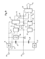
- Détecteur de position selon la revendication 3 ou l'une des revendications 4 à 6 si celles-ci sont dépendantes de la revendication 3, caractérisé en ce que le circuit de commande comprend les composants suivants- une première mémoire (70), qui est chargée à l'apparition d'un signal de détection d'impulsion et émet un niveau de signal de comptage,- une deuxième mémoire (72), qui est chargée à l'apparition d'un signal de demande et émet un niveau de signal de blocage,- un circuit de blocage (74) avec deux entrées, dont l'une est reliée à la sortie de la première mémoire (70) et l'autre à la sortie de la deuxième mémoire (72), lequel n'autorise le niveau de signal de comptage sur une entrée de comptage, sensible aux flancs, du circuit de comptage et de mémorisation (32) pour le déclenchement d'un processus de comptage et de mémorisation, que si aucun niveau de signal de blocage n'est appliqué sur son autre entrée,- en ce qu'une impulsion de réinitialisation est émise vers la première mémoire (70) à l'issue du processus de mémorisation dans le circuit de comptage et de mémorisation (32), et- en ce qu'une impulsion de réinitialisation est émise vers la deuxième mémoire (72) à l'issue de la sortie de données vers l'utilisateur,
le circuit de commande (30) étant en fonction de la disponibilité alimenté en énergie électrique soit par l'alimentation en courant externe, soit par le ou les condensateurs (28). - Détecteur de position selon la revendication 1 ou la revendication 2, caractérisé en ce que le circuit redresseur (24, 24') ne se compose que d'une seule diode.
- Détecteur de position selon la revendication 1 ou la revendication 2, caractérisé en ce que le circuit redresseur (24, 24') se compose d'un transistor de commutation, qui est commutable en va-et-vient entre un état de conduction, où il reçoit une tension de conduction minimale, et un état de blocage, où il ne conduit pas de courant.
- Détecteur de position selon la revendication 1 ou la revendication 2, caractérisé en ce que le circuit redresseur (24) est un circuit en pont de Graetz, dont les diodes sont court-circuitables par paires par des transistors qui leur sont parallèles.
- Détecteur de position selon l'une des revendications précédentes, caractérisé en ce que le circuit de comptage et de mémorisation non volatil (32) est une FRAM.
- Détecteur de position selon l'une des revendications précédentes, caractérisé en ce que l'élément ferromagnétique (6) est un fil à impulsions.
- Détecteur de position selon l'une des revendications 1 à 11, caractérisé en ce que l'élément ferromagnétique (6) est un fil Wiegand.
- Détecteur de position selon l'une des revendications précédentes, caractérisé en ce que les unités de circuit de l'électronique et, si présents, le circuit limiteur de tension (26), l'autre circuit redresseur (24') et l'autre condensateur (28') sont regroupés dans un module de circuit intégré (20).
- Détecteur de position selon l'une des revendications 1 à 13, caractérisé en ce qu'au moins quelques-unes des unités de circuit de l'électronique et/ou, si présents, le circuit limiteur de tension (26), l'autre circuit redresseur (24') et l'autre condensateur (28') sont regroupés dans un module de circuit intégré (20).
- Détecteur de position selon l'une des revendications précédentes, caractérisé en ce que l'aimant d'excitation (2) et l'élément ferromagnétique (6) sont situés par leurs axes longitudinaux (3, 10) sur deux plans parallèles dont la normale commune est l'axe de rotation (4).
- Détecteur de position selon l'une des revendications 1 à 15, caractérisé en ce que les centres de gravité géométriques de deux aimants d'excitation (3, 9) de polarités opposées et de l'élément ferromagnétique (6) sont situés sur un plan dont la normale est l'axe de rotation (4), et en ce que les axes longitudinaux (3, 10) de ces éléments s'étendent parallèlement à l'axe de rotation (4).
- Détecteur de position selon l'une des revendications 1 à 15, caractérisé en ce que l'aimant d'excitation (2) et l'élément ferromagnétique (6) sont situés sur un plan dont la normale est l'axe de rotation (4), et en ce que l'élément ferromagnétique (6) et l'aimant d'excitation (2) sont disposés radialement à l'axe de rotation (4).
- Détecteur de position selon l'une des revendications 1 à 15, caractérisé en ce que l'aimant d'excitation (2) et l'élément ferromagnétique (6) sont situés sur un plan et orientés perpendiculairement l'un à l'autre.
- Détecteur de position selon l'une des revendications 2 à 19, caractérisé en ce qu'un émetteur est affecté au circuit de lecture de données (34'), lequel rend les données du circuit de comptage et de mémorisation (32) disponibles à un circuit de réception pour l'utilisateur, via une liaison radioélectrique.
- Détecteur de position selon l'une des revendications précédentes, caractérisé en ce que le circuit de lecture de données (34, 34') sert aussi à l'extraction de données caractéristiques vers le circuit de comptage et de mémorisation non volatil (32).
Applications Claiming Priority (6)
| Application Number | Priority Date | Filing Date | Title |
|---|---|---|---|
| DE20320021U | 2003-12-24 | ||
| DE20320021 | 2003-12-24 | ||
| DE202004000413U | 2004-01-13 | ||
| DE202004000413U DE202004000413U1 (de) | 2003-12-24 | 2004-01-13 | Positionsdetektor |
| DE202004002273U | 2004-02-13 | ||
| DE200420002273 DE202004002273U1 (de) | 2004-02-13 | 2004-02-13 | Positionsdetektor |
Publications (3)
| Publication Number | Publication Date |
|---|---|
| EP1550845A1 EP1550845A1 (fr) | 2005-07-06 |
| EP1550845B1 true EP1550845B1 (fr) | 2011-08-31 |
| EP1550845B2 EP1550845B2 (fr) | 2022-05-04 |
Family
ID=44585020
Family Applications (1)
| Application Number | Title | Priority Date | Filing Date |
|---|---|---|---|
| EP04030527.8A Expired - Lifetime EP1550845B2 (fr) | 2003-12-24 | 2004-12-22 | détecteur de position |
Country Status (2)
| Country | Link |
|---|---|
| EP (1) | EP1550845B2 (fr) |
| AT (1) | ATE522787T1 (fr) |
Families Citing this family (7)
| Publication number | Priority date | Publication date | Assignee | Title |
|---|---|---|---|---|
| CN103827011B (zh) | 2011-09-29 | 2016-10-26 | 因温特奥股份公司 | 用于监控竖井门的设备和方法 |
| DE102012102308B4 (de) * | 2012-03-19 | 2024-11-07 | Ic-Haus Gmbh | Verfahren zur Detektion von Spannungsimpulsen, Schaltungsanordnung und Positionsmessvorrichtung |
| DE102012012874B4 (de) * | 2012-06-28 | 2019-06-19 | Sew-Eurodrive Gmbh & Co Kg | Anordnung zur Bestimmung einer Umdrehungsanzahl einer drehbar gelagerten Welle und Verfahren zur Bestimmung einer Umdrehungsanzahl einer drehbar gelagerten Welle |
| CN107817377A (zh) * | 2017-11-17 | 2018-03-20 | 国网江苏省电力有限公司检修分公司 | 一种基于传感器外置有效抑制干扰的隐患行波检测装置 |
| US20210131586A1 (en) * | 2019-11-04 | 2021-05-06 | Emerson Process Management Valve Automation, Inc. | Electric Valve Actuator with Energy Harvesting Position Detector Assemblies |
| DE102022124159B4 (de) | 2022-09-21 | 2024-04-11 | Fachhochschule Aachen, Körperschaft d. öffentl. Rechts | Positionssensorvorrichtung |
| CN118168584B (zh) * | 2024-05-14 | 2024-07-19 | 电子科技大学 | 一种用于伺服电机的多圈编码器装置 |
Citations (4)
| Publication number | Priority date | Publication date | Assignee | Title |
|---|---|---|---|---|
| EP0133735A2 (fr) | 1983-08-03 | 1985-03-06 | Hewlett-Packard Company | Dispositif de compteur à N-bits |
| US4881248A (en) | 1986-08-28 | 1989-11-14 | Nec Corporation | Counter circuit provided with means for reading out counted data by read-command signal applied asynchronously with clock signals to be counted |
| DE10012337A1 (de) | 2000-03-14 | 2001-10-11 | Peter Fischer | Schaltungsanordnung zum kontinuierlichen Zählen von Impulsen ohne Totzeit |
| WO2004046735A1 (fr) | 2002-11-20 | 2004-06-03 | Walter Mehnert | Detecteur de position |
Family Cites Families (7)
| Publication number | Priority date | Publication date | Assignee | Title |
|---|---|---|---|---|
| DE2907776A1 (de) † | 1979-02-28 | 1980-09-11 | Siemens Ag | Verfahren zur absicherung des in einer hauptdatei gespeicherten zentralen datenbestandes |
| JPH06314968A (ja) † | 1993-04-28 | 1994-11-08 | Fujitsu Ltd | カウンタのリード制御方法 |
| DE4413281C2 (de) * | 1994-04-16 | 1996-02-22 | Walter Dr Mehnert | Stellungsgeber mit Datenauswerteschaltung |
| DE4407474C2 (de) * | 1994-03-07 | 2000-07-13 | Asm Automation Sensorik Messte | Drehwinkelsensor |
| US6191687B1 (en) * | 1998-09-24 | 2001-02-20 | Hid Corporation | Wiegand effect energy generator |
| US6628741B2 (en) * | 2001-11-20 | 2003-09-30 | Netzer Precision Motion Sensors Ltd. | Non-volatile passive revolution counter with reed magnetic sensor |
| DE10245126B3 (de) † | 2002-09-27 | 2004-04-15 | Fraunhofer-Gesellschaft zur Förderung der angewandten Forschung e.V. | Unterbrechungsfrei auslesbarer digitaler Zähler sowie Verfahren zum Zählen von Zählimpulsen |
-
2004
- 2004-12-22 AT AT04030527T patent/ATE522787T1/de active
- 2004-12-22 EP EP04030527.8A patent/EP1550845B2/fr not_active Expired - Lifetime
Patent Citations (4)
| Publication number | Priority date | Publication date | Assignee | Title |
|---|---|---|---|---|
| EP0133735A2 (fr) | 1983-08-03 | 1985-03-06 | Hewlett-Packard Company | Dispositif de compteur à N-bits |
| US4881248A (en) | 1986-08-28 | 1989-11-14 | Nec Corporation | Counter circuit provided with means for reading out counted data by read-command signal applied asynchronously with clock signals to be counted |
| DE10012337A1 (de) | 2000-03-14 | 2001-10-11 | Peter Fischer | Schaltungsanordnung zum kontinuierlichen Zählen von Impulsen ohne Totzeit |
| WO2004046735A1 (fr) | 2002-11-20 | 2004-06-03 | Walter Mehnert | Detecteur de position |
Also Published As
| Publication number | Publication date |
|---|---|
| EP1550845A1 (fr) | 2005-07-06 |
| EP1550845B2 (fr) | 2022-05-04 |
| ATE522787T1 (de) | 2011-09-15 |
Similar Documents
| Publication | Publication Date | Title |
|---|---|---|
| EP0679868B1 (fr) | Capteur de position avec circuit d'évaluation | |
| DE2708656C2 (de) | Verfahren zum wahlweisen Abrufen von Daten von einer von mehreren entfernt liegenden Datenerfassungsstellen und Einrichtung zur Ausführung dieses Verfahrens | |
| DE2740533C2 (de) | Fernwirkverfahren und Fernwirkanlage zur Durchführung des Verfahrens | |
| EP1565755B2 (fr) | Detecteur de position | |
| DE102009034744A1 (de) | Absoluter magnetischer Positionsgeber | |
| EP0658745A2 (fr) | Capteur de position | |
| DE102015117064B4 (de) | Positionsdetektor | |
| DE102018215796A1 (de) | Positionserfassungssystem und Verfahren zur Erfassung einer Bewegung einer Maschine | |
| EP1550845B1 (fr) | Détecteur de position | |
| EP0322698A1 (fr) | Méthode pour la transmission d'informations | |
| DE1960170C3 (de) | Störungssichere Torschaltung | |
| DE202004000413U1 (de) | Positionsdetektor | |
| DE102017203676B4 (de) | Magnetischer absoluter Positionssensor | |
| DE102004055626B3 (de) | Vorrichtung zum Erfassen von Bewegungen und/oder Positionen eines Gegenstandes | |
| EP0898368A2 (fr) | Dispositif capteur | |
| DE3300218C2 (de) | Datenfernübertragungssystem | |
| DE202004002273U1 (de) | Positionsdetektor | |
| DE102017203679B4 (de) | Zählsensor mit Korrekturfunktion | |
| DE102017203683B4 (de) | Zählsensor mit korrekturfunktion | |
| DE2853813A1 (de) | Impulsgabe-einrichtung fuer einen elektrizitaetszaehler | |
| DE19933686A1 (de) | Schalter mit drahtloser Fernablesung | |
| DE102015117080A1 (de) | Magnetischer absoluter Positionssensor | |
| DE2525070B2 (de) | Informationsleseeinheit für von einem Förderer mitgefühlte Steuerinformationen | |
| DE1563651C (de) | Empfangsgerät zur Aufnahme von Steuersignalen | |
| DE1537819C3 (de) | Schaltungsanordnung zum Abfragen von Teilnehmerstellen auf ihren Betriebszustand, insbesondere für Zeitmultiplex -Vermittlungsanlagen |
Legal Events
| Date | Code | Title | Description |
|---|---|---|---|
| PUAI | Public reference made under article 153(3) epc to a published international application that has entered the european phase |
Free format text: ORIGINAL CODE: 0009012 |
|
| AK | Designated contracting states |
Kind code of ref document: A1 Designated state(s): AT BE BG CH CY CZ DE DK EE ES FI FR GB GR HU IE IS IT LI LT LU MC NL PL PT RO SE SI SK TR |
|
| AX | Request for extension of the european patent |
Extension state: AL BA HR LV MK YU |
|
| 17P | Request for examination filed |
Effective date: 20051230 |
|
| AKX | Designation fees paid |
Designated state(s): AT BE BG CH CY CZ DE DK EE ES FI FR GB GR HU IE IS IT LI LT LU MC NL PL PT RO SE SI SK TR |
|
| 17Q | First examination report despatched |
Effective date: 20071221 |
|
| GRAP | Despatch of communication of intention to grant a patent |
Free format text: ORIGINAL CODE: EPIDOSNIGR1 |
|
| GRAS | Grant fee paid |
Free format text: ORIGINAL CODE: EPIDOSNIGR3 |
|
| GRAA | (expected) grant |
Free format text: ORIGINAL CODE: 0009210 |
|
| RAP1 | Party data changed (applicant data changed or rights of an application transferred) |
Owner name: THEIL, THOMAS Owner name: MEHNERT, WALTER |
|
| RIN1 | Information on inventor provided before grant (corrected) |
Inventor name: THEIL, THOMAS Inventor name: MEHNERT, WALTER |
|
| AK | Designated contracting states |
Kind code of ref document: B1 Designated state(s): AT BE BG CH CY CZ DE DK EE ES FI FR GB GR HU IE IS IT LI LT LU MC NL PL PT RO SE SI SK TR |
|
| REG | Reference to a national code |
Ref country code: GB Ref legal event code: FG4D Free format text: NOT ENGLISH Ref country code: CH Ref legal event code: EP |
|
| REG | Reference to a national code |
Ref country code: IE Ref legal event code: FG4D Free format text: LANGUAGE OF EP DOCUMENT: GERMAN |
|
| REG | Reference to a national code |
Ref country code: DE Ref legal event code: R096 Ref document number: 502004012834 Country of ref document: DE Effective date: 20111027 |
|
| REG | Reference to a national code |
Ref country code: CH Ref legal event code: NV Representative=s name: BOVARD AG |
|
| REG | Reference to a national code |
Ref country code: NL Ref legal event code: T3 |
|
| REG | Reference to a national code |
Ref country code: DE Ref legal event code: R081 Ref document number: 502004012834 Country of ref document: DE Owner name: MEHNERT, WALTER, DR., DE Free format text: FORMER OWNER: WALTER MEHNERT,THOMAS DR. THEIL, , DE Effective date: 20110901 Ref country code: DE Ref legal event code: R081 Ref document number: 502004012834 Country of ref document: DE Owner name: MEHNERT, WALTER, DR., DE Free format text: FORMER OWNER: WALTER MEHNERT,THOMAS THEIL, , DE Effective date: 20111103 Ref country code: DE Ref legal event code: R081 Ref document number: 502004012834 Country of ref document: DE Owner name: THEIL, THOMAS, DR., DE Free format text: FORMER OWNER: WALTER MEHNERT,THOMAS DR. THEIL, , DE Effective date: 20110901 Ref country code: DE Ref legal event code: R081 Ref document number: 502004012834 Country of ref document: DE Owner name: THEIL, THOMAS, DR., DE Free format text: FORMER OWNER: WALTER MEHNERT,THOMAS THEIL, , DE Effective date: 20111103 Ref country code: DE Ref legal event code: R082 Ref document number: 502004012834 Country of ref document: DE Representative=s name: STROHSCHAENK UND KOLLEGEN, DE Effective date: 20111103 Ref country code: DE Ref legal event code: R081 Ref document number: 502004012834 Country of ref document: DE Owner name: THEIL, THOMAS, DR., DE Free format text: FORMER OWNERS: MEHNERT, WALTER, DIPL.-ING. DR.-ING., 85521 OTTOBRUNN, DE; THEIL, THOMAS DR., 85258 WEICHS, DE Effective date: 20110901 Ref country code: DE Ref legal event code: R082 Ref document number: 502004012834 Country of ref document: DE Representative=s name: PATENTANWAELTE STROHSCHAENK, URI, STRASSER & K, DE Effective date: 20111103 Ref country code: DE Ref legal event code: R081 Ref document number: 502004012834 Country of ref document: DE Owner name: MEHNERT, WALTER, DR., DE Free format text: FORMER OWNERS: MEHNERT, WALTER, DIPL.-ING. DR.-ING., 85521 OTTOBRUNN, DE; THEIL, THOMAS DR., 85258 WEICHS, DE Effective date: 20110901 Ref country code: DE Ref legal event code: R081 Ref document number: 502004012834 Country of ref document: DE Owner name: MEHNERT, WALTER, DR., DE Free format text: FORMER OWNERS: MEHNERT, WALTER, DR., 85521 OTTOBRUNN, DE; THEIL, THOMAS, DR., 85258 WEICHS, DE Effective date: 20111103 Ref country code: DE Ref legal event code: R081 Ref document number: 502004012834 Country of ref document: DE Owner name: THEIL, THOMAS, DR., DE Free format text: FORMER OWNERS: MEHNERT, WALTER, DR., 85521 OTTOBRUNN, DE; THEIL, THOMAS, DR., 85258 WEICHS, DE Effective date: 20111103 Ref country code: DE Ref legal event code: R082 Ref document number: 502004012834 Country of ref document: DE Representative=s name: DILG HAEUSLER SCHINDELMANN PATENTANWALTSGESELL, DE Effective date: 20111103 |
|
| LTIE | Lt: invalidation of european patent or patent extension |
Effective date: 20110831 |
|
| PG25 | Lapsed in a contracting state [announced via postgrant information from national office to epo] |
Ref country code: SE Free format text: LAPSE BECAUSE OF FAILURE TO SUBMIT A TRANSLATION OF THE DESCRIPTION OR TO PAY THE FEE WITHIN THE PRESCRIBED TIME-LIMIT Effective date: 20110831 Ref country code: FI Free format text: LAPSE BECAUSE OF FAILURE TO SUBMIT A TRANSLATION OF THE DESCRIPTION OR TO PAY THE FEE WITHIN THE PRESCRIBED TIME-LIMIT Effective date: 20110831 Ref country code: IS Free format text: LAPSE BECAUSE OF FAILURE TO SUBMIT A TRANSLATION OF THE DESCRIPTION OR TO PAY THE FEE WITHIN THE PRESCRIBED TIME-LIMIT Effective date: 20111231 Ref country code: LT Free format text: LAPSE BECAUSE OF FAILURE TO SUBMIT A TRANSLATION OF THE DESCRIPTION OR TO PAY THE FEE WITHIN THE PRESCRIBED TIME-LIMIT Effective date: 20110831 |
|
| PGFP | Annual fee paid to national office [announced via postgrant information from national office to epo] |
Ref country code: NL Payment date: 20111221 Year of fee payment: 8 |
|
| PG25 | Lapsed in a contracting state [announced via postgrant information from national office to epo] |
Ref country code: CY Free format text: LAPSE BECAUSE OF FAILURE TO SUBMIT A TRANSLATION OF THE DESCRIPTION OR TO PAY THE FEE WITHIN THE PRESCRIBED TIME-LIMIT Effective date: 20110831 Ref country code: SI Free format text: LAPSE BECAUSE OF FAILURE TO SUBMIT A TRANSLATION OF THE DESCRIPTION OR TO PAY THE FEE WITHIN THE PRESCRIBED TIME-LIMIT Effective date: 20110831 Ref country code: GR Free format text: LAPSE BECAUSE OF FAILURE TO SUBMIT A TRANSLATION OF THE DESCRIPTION OR TO PAY THE FEE WITHIN THE PRESCRIBED TIME-LIMIT Effective date: 20111201 |
|
| REG | Reference to a national code |
Ref country code: IE Ref legal event code: FD4D |
|
| PG25 | Lapsed in a contracting state [announced via postgrant information from national office to epo] |
Ref country code: SK Free format text: LAPSE BECAUSE OF FAILURE TO SUBMIT A TRANSLATION OF THE DESCRIPTION OR TO PAY THE FEE WITHIN THE PRESCRIBED TIME-LIMIT Effective date: 20110831 Ref country code: IE Free format text: LAPSE BECAUSE OF FAILURE TO SUBMIT A TRANSLATION OF THE DESCRIPTION OR TO PAY THE FEE WITHIN THE PRESCRIBED TIME-LIMIT Effective date: 20110831 Ref country code: CZ Free format text: LAPSE BECAUSE OF FAILURE TO SUBMIT A TRANSLATION OF THE DESCRIPTION OR TO PAY THE FEE WITHIN THE PRESCRIBED TIME-LIMIT Effective date: 20110831 |
|
| PG25 | Lapsed in a contracting state [announced via postgrant information from national office to epo] |
Ref country code: RO Free format text: LAPSE BECAUSE OF FAILURE TO SUBMIT A TRANSLATION OF THE DESCRIPTION OR TO PAY THE FEE WITHIN THE PRESCRIBED TIME-LIMIT Effective date: 20110831 Ref country code: EE Free format text: LAPSE BECAUSE OF FAILURE TO SUBMIT A TRANSLATION OF THE DESCRIPTION OR TO PAY THE FEE WITHIN THE PRESCRIBED TIME-LIMIT Effective date: 20110831 Ref country code: PT Free format text: LAPSE BECAUSE OF FAILURE TO SUBMIT A TRANSLATION OF THE DESCRIPTION OR TO PAY THE FEE WITHIN THE PRESCRIBED TIME-LIMIT Effective date: 20120102 Ref country code: PL Free format text: LAPSE BECAUSE OF FAILURE TO SUBMIT A TRANSLATION OF THE DESCRIPTION OR TO PAY THE FEE WITHIN THE PRESCRIBED TIME-LIMIT Effective date: 20110831 |
|
| PLBI | Opposition filed |
Free format text: ORIGINAL CODE: 0009260 |
|
| PG25 | Lapsed in a contracting state [announced via postgrant information from national office to epo] |
Ref country code: DK Free format text: LAPSE BECAUSE OF FAILURE TO SUBMIT A TRANSLATION OF THE DESCRIPTION OR TO PAY THE FEE WITHIN THE PRESCRIBED TIME-LIMIT Effective date: 20110831 |
|
| BERE | Be: lapsed |
Owner name: MEHNERT, WALTER Effective date: 20111231 Owner name: THEIL, THOMAS Effective date: 20111231 |
|
| PLAX | Notice of opposition and request to file observation + time limit sent |
Free format text: ORIGINAL CODE: EPIDOSNOBS2 |
|
| 26 | Opposition filed |
Opponent name: ASM AUTOMATION SENSORIK MESSTECHNIK GMBH Effective date: 20120531 |
|
| PG25 | Lapsed in a contracting state [announced via postgrant information from national office to epo] |
Ref country code: MC Free format text: LAPSE BECAUSE OF NON-PAYMENT OF DUE FEES Effective date: 20111231 |
|
| REG | Reference to a national code |
Ref country code: DE Ref legal event code: R026 Ref document number: 502004012834 Country of ref document: DE Effective date: 20120531 |
|
| PG25 | Lapsed in a contracting state [announced via postgrant information from national office to epo] |
Ref country code: BE Free format text: LAPSE BECAUSE OF NON-PAYMENT OF DUE FEES Effective date: 20111231 |
|
| PLAF | Information modified related to communication of a notice of opposition and request to file observations + time limit |
Free format text: ORIGINAL CODE: EPIDOSCOBS2 |
|
| PLBB | Reply of patent proprietor to notice(s) of opposition received |
Free format text: ORIGINAL CODE: EPIDOSNOBS3 |
|
| PG25 | Lapsed in a contracting state [announced via postgrant information from national office to epo] |
Ref country code: ES Free format text: LAPSE BECAUSE OF FAILURE TO SUBMIT A TRANSLATION OF THE DESCRIPTION OR TO PAY THE FEE WITHIN THE PRESCRIBED TIME-LIMIT Effective date: 20111211 |
|
| PG25 | Lapsed in a contracting state [announced via postgrant information from national office to epo] |
Ref country code: LU Free format text: LAPSE BECAUSE OF NON-PAYMENT OF DUE FEES Effective date: 20111222 |
|
| PG25 | Lapsed in a contracting state [announced via postgrant information from national office to epo] |
Ref country code: BG Free format text: LAPSE BECAUSE OF FAILURE TO SUBMIT A TRANSLATION OF THE DESCRIPTION OR TO PAY THE FEE WITHIN THE PRESCRIBED TIME-LIMIT Effective date: 20111130 |
|
| RDAF | Communication despatched that patent is revoked |
Free format text: ORIGINAL CODE: EPIDOSNREV1 |
|
| REG | Reference to a national code |
Ref country code: NL Ref legal event code: V1 Effective date: 20130701 |
|
| REG | Reference to a national code |
Ref country code: AT Ref legal event code: MM01 Ref document number: 522787 Country of ref document: AT Kind code of ref document: T Effective date: 20121222 |
|
| APBM | Appeal reference recorded |
Free format text: ORIGINAL CODE: EPIDOSNREFNO |
|
| APBP | Date of receipt of notice of appeal recorded |
Free format text: ORIGINAL CODE: EPIDOSNNOA2O |
|
| APAH | Appeal reference modified |
Free format text: ORIGINAL CODE: EPIDOSCREFNO |
|
| PG25 | Lapsed in a contracting state [announced via postgrant information from national office to epo] |
Ref country code: TR Free format text: LAPSE BECAUSE OF FAILURE TO SUBMIT A TRANSLATION OF THE DESCRIPTION OR TO PAY THE FEE WITHIN THE PRESCRIBED TIME-LIMIT Effective date: 20110831 |
|
| PG25 | Lapsed in a contracting state [announced via postgrant information from national office to epo] |
Ref country code: NL Free format text: LAPSE BECAUSE OF NON-PAYMENT OF DUE FEES Effective date: 20130701 Ref country code: AT Free format text: LAPSE BECAUSE OF NON-PAYMENT OF DUE FEES Effective date: 20121222 Ref country code: HU Free format text: LAPSE BECAUSE OF FAILURE TO SUBMIT A TRANSLATION OF THE DESCRIPTION OR TO PAY THE FEE WITHIN THE PRESCRIBED TIME-LIMIT Effective date: 20110831 |
|
| APBQ | Date of receipt of statement of grounds of appeal recorded |
Free format text: ORIGINAL CODE: EPIDOSNNOA3O |
|
| PLAB | Opposition data, opponent's data or that of the opponent's representative modified |
Free format text: ORIGINAL CODE: 0009299OPPO |
|
| R26 | Opposition filed (corrected) |
Opponent name: ASM AUTOMATION SENSORIK MESSTECHNIK GMBH Effective date: 20120531 |
|
| REG | Reference to a national code |
Ref country code: FR Ref legal event code: PLFP Year of fee payment: 12 |
|
| PLAB | Opposition data, opponent's data or that of the opponent's representative modified |
Free format text: ORIGINAL CODE: 0009299OPPO |
|
| REG | Reference to a national code |
Ref country code: DE Ref legal event code: R082 Ref document number: 502004012834 Country of ref document: DE Representative=s name: KILIAN KILIAN & PARTNER MBB PATENTANWAELTE, DE Ref country code: DE Ref legal event code: R082 Ref document number: 502004012834 Country of ref document: DE Representative=s name: DILG, HAEUSLER, SCHINDELMANN PATENTANWALTSGESE, DE Ref country code: DE Ref legal event code: R082 Ref document number: 502004012834 Country of ref document: DE Representative=s name: DILG HAEUSLER SCHINDELMANN PATENTANWALTSGESELL, DE |
|
| R26 | Opposition filed (corrected) |
Opponent name: ASM AUTOMATION SENSORIK MESSTECHNIK GMBH Effective date: 20120531 |
|
| REG | Reference to a national code |
Ref country code: FR Ref legal event code: PLFP Year of fee payment: 13 |
|
| RAP2 | Party data changed (patent owner data changed or rights of a patent transferred) |
Owner name: AVAGO TECHNOLOGIES GENERAL IP (SINGAPORE) PTE. LTD |
|
| RIN2 | Information on inventor provided after grant (corrected) |
Inventor name: MEHNERT, WALTER Inventor name: THEIL, THOMAS |
|
| APBU | Appeal procedure closed |
Free format text: ORIGINAL CODE: EPIDOSNNOA9O |
|
| REG | Reference to a national code |
Ref country code: FR Ref legal event code: PLFP Year of fee payment: 14 |
|
| REG | Reference to a national code |
Ref country code: DE Ref legal event code: R082 Ref document number: 502004012834 Country of ref document: DE Representative=s name: DILG, HAEUSLER, SCHINDELMANN PATENTANWALTSGESE, DE Ref country code: DE Ref legal event code: R082 Ref document number: 502004012834 Country of ref document: DE Representative=s name: DILG HAEUSLER SCHINDELMANN PATENTANWALTSGESELL, DE Ref country code: DE Ref legal event code: R081 Ref document number: 502004012834 Country of ref document: DE Owner name: AVAGO TECHNOLOGIES GENERAL IP (SINGAPORE) PTE., SG Free format text: FORMER OWNERS: MEHNERT, WALTER, DR., 85521 OTTOBRUNN, DE; THEIL, THOMAS, DR., 82340 FELDAFING, DE Ref country code: DE Ref legal event code: R081 Ref document number: 502004012834 Country of ref document: DE Owner name: AVAGO TECHNOLOGIES INTERNATIONAL SALES PTE. LI, SG Free format text: FORMER OWNERS: MEHNERT, WALTER, DR., 85521 OTTOBRUNN, DE; THEIL, THOMAS, DR., 82340 FELDAFING, DE |
|
| REG | Reference to a national code |
Ref country code: CH Ref legal event code: PUE Owner name: AVAGO TECHNOLOGIES INTERNATIONAL SALES PTE. LI, SG Free format text: FORMER OWNER: MEHNERT, WALTER, DE |
|
| REG | Reference to a national code |
Ref country code: GB Ref legal event code: 732E Free format text: REGISTERED BETWEEN 20181025 AND 20181102 |
|
| REG | Reference to a national code |
Ref country code: DE Ref legal event code: R082 Ref document number: 502004012834 Country of ref document: DE Representative=s name: DILG, HAEUSLER, SCHINDELMANN PATENTANWALTSGESE, DE Ref country code: DE Ref legal event code: R082 Ref document number: 502004012834 Country of ref document: DE Representative=s name: DILG HAEUSLER SCHINDELMANN PATENTANWALTSGESELL, DE Ref country code: DE Ref legal event code: R081 Ref document number: 502004012834 Country of ref document: DE Owner name: AVAGO TECHNOLOGIES INTERNATIONAL SALES PTE. LI, SG Free format text: FORMER OWNER: AVAGO TECHNOLOGIES GENERAL IP (SINGAPORE) PTE. LTD., SINGAPORE, SG |
|
| REG | Reference to a national code |
Ref country code: GB Ref legal event code: 732E Free format text: REGISTERED BETWEEN 20190110 AND 20190116 |
|
| APAH | Appeal reference modified |
Free format text: ORIGINAL CODE: EPIDOSCREFNO |
|
| APBM | Appeal reference recorded |
Free format text: ORIGINAL CODE: EPIDOSNREFNO |
|
| APBP | Date of receipt of notice of appeal recorded |
Free format text: ORIGINAL CODE: EPIDOSNNOA2O |
|
| APBQ | Date of receipt of statement of grounds of appeal recorded |
Free format text: ORIGINAL CODE: EPIDOSNNOA3O |
|
| RAP2 | Party data changed (patent owner data changed or rights of a patent transferred) |
Owner name: AVAGO TECHNOLOGIES INTERNATIONAL SALES PTE. LIMITE |
|
| APBU | Appeal procedure closed |
Free format text: ORIGINAL CODE: EPIDOSNNOA9O |
|
| PUAH | Patent maintained in amended form |
Free format text: ORIGINAL CODE: 0009272 |
|
| STAA | Information on the status of an ep patent application or granted ep patent |
Free format text: STATUS: PATENT MAINTAINED AS AMENDED |
|
| 27A | Patent maintained in amended form |
Effective date: 20220504 |
|
| AK | Designated contracting states |
Kind code of ref document: B2 Designated state(s): AT BE BG CH CY CZ DE DK EE ES FI FR GB GR HU IE IS IT LI LT LU MC NL PL PT RO SE SI SK TR |
|
| REG | Reference to a national code |
Ref country code: DE Ref legal event code: R102 Ref document number: 502004012834 Country of ref document: DE |
|
| REG | Reference to a national code |
Ref country code: DE Ref legal event code: R082 Ref document number: 502004012834 Country of ref document: DE Representative=s name: KILIAN KILIAN & PARTNER MBB PATENTANWAELTE, DE |
|
| PGFP | Annual fee paid to national office [announced via postgrant information from national office to epo] |
Ref country code: GB Payment date: 20231121 Year of fee payment: 20 |
|
| PGFP | Annual fee paid to national office [announced via postgrant information from national office to epo] |
Ref country code: FR Payment date: 20231122 Year of fee payment: 20 Ref country code: DE Payment date: 20231211 Year of fee payment: 20 |
|
| PGFP | Annual fee paid to national office [announced via postgrant information from national office to epo] |
Ref country code: CH Payment date: 20240101 Year of fee payment: 20 |
|
| REG | Reference to a national code |
Ref country code: DE Ref legal event code: R071 Ref document number: 502004012834 Country of ref document: DE |
|
| REG | Reference to a national code |
Ref country code: CH Ref legal event code: PL |
|
| REG | Reference to a national code |
Ref country code: GB Ref legal event code: PE20 Expiry date: 20241221 |
|
| PG25 | Lapsed in a contracting state [announced via postgrant information from national office to epo] |
Ref country code: GB Free format text: LAPSE BECAUSE OF EXPIRATION OF PROTECTION Effective date: 20241221 |
|
| PG25 | Lapsed in a contracting state [announced via postgrant information from national office to epo] |
Ref country code: GB Free format text: LAPSE BECAUSE OF EXPIRATION OF PROTECTION Effective date: 20241221 |
|
| PGFP | Annual fee paid to national office [announced via postgrant information from national office to epo] |
Ref country code: IT Payment date: 20231121 Year of fee payment: 20 |