EP1550844B1 - Einrichtung zur Detektion des Drehens eines rotierenden Elements, wie einer Wasserzählerturbine - Google Patents
Einrichtung zur Detektion des Drehens eines rotierenden Elements, wie einer Wasserzählerturbine Download PDFInfo
- Publication number
- EP1550844B1 EP1550844B1 EP04300958A EP04300958A EP1550844B1 EP 1550844 B1 EP1550844 B1 EP 1550844B1 EP 04300958 A EP04300958 A EP 04300958A EP 04300958 A EP04300958 A EP 04300958A EP 1550844 B1 EP1550844 B1 EP 1550844B1
- Authority
- EP
- European Patent Office
- Prior art keywords
- detector
- mark
- comparison
- detectors
- amplitude
- Prior art date
- Legal status (The legal status is an assumption and is not a legal conclusion. Google has not performed a legal analysis and makes no representation as to the accuracy of the status listed.)
- Expired - Lifetime
Links
Images


Classifications
-
- G—PHYSICS
- G01—MEASURING; TESTING
- G01F—MEASURING VOLUME, VOLUME FLOW, MASS FLOW OR LIQUID LEVEL; METERING BY VOLUME
- G01F15/00—Details of, or accessories for, apparatus of groups G01F1/00 - G01F13/00 insofar as such details or appliances are not adapted to particular types of such apparatus
- G01F15/06—Indicating or recording devices
Definitions
- the invention relates to a device for detecting rotation of a rotating element such as the turbine of a water meter.
- Most water meters include a mechanical drive totalizer, ie the rotation of the turbine drives, through a mechanical and / or magnetic transmission, the rollers of the counter index.
- the proximity detector may for example be based on an inductive method, in which case the mark will be constituted by a material whose magnetic and / or electrical characteristics different from the rest of the rotating element.
- the figure 1 illustrates such a detection mode.
- the rotating assembly consists of a turbine 1 of a not shown flowmeter and a disc 2 integral with the turbine 1. When a fluid such as water flows, the turbine 1 and the disc 2 are animated with a rotational movement about the axis XX '. The rotational speed of the rotating element is directly related to the instantaneous flow rate of the fluid.
- Two proximity detectors L0 and L1 situated in a plane P perpendicular to the axis XX ', in two radial directions with respect to the axis XX' are sensitive to the proximity of a mark 5 which is integral with the disc 2 and off-center relative to the axis of rotation XX '. It follows that when the rotating element is driven by a rotational movement, the response of proximity sensors L0 and L1 will change according to the position of the mark 5.
- the two proximity sensors L0 and L1 are for example magnetic coils coupled in parallel with capacitors thus forming two oscillating circuits arranged in two opposite radial directions.
- the disc 2 is made of non-metallic material such only molded plastic and the mark 5 is a metallized radial sector of the disc.
- the document DE 41 37 695 A1 describes a device comprising two detectors adjacent to a rotor.
- the rotor comprises two sectors having different magnetic properties.
- the response of each detector to excitation, in particular the damping time makes it possible to determine which sector is close to the detector.
- the damping time is measured in the number of oscillations exceeding a threshold.
- Such a detection system poses certain difficulties; indeed, there is a series of parameters that varies with time. For example, for a water meter integrated in a calorimeter, it is the water temperature that can vary the characteristics of the detector, the supply voltage of the detection circuit, especially when the power supply is via a battery, and the variable distance between the proximity sensor and the rotating element due to the high speed turbine lift. There is also a series of parameters which vary from detector to detector and which are difficult and expensive to control in mass production; for example, for a detector of the inductive type, these are in particular the values of the coil and its quality coefficient, which leads to a calibration of each detector or a sorting.
- the rotation detection device described in this document comprises at least two proximity sensors intended to detect the passage of a mark integral with the rotating element.
- the device performs an analysis of the evolution of the signal delivered by a first detector.
- the index of the number of revolutions is incremented and the second detector is selected, thereby excluding the first detector which has just detected the mark; the parameters intended to study the evolution of the signals of the second detector are then reinitialized and thus an adaptive system is obtained making it possible to overcome the problems related to the variation of the parameters.
- the device of this solution uses a complex electronic circuit therefore entailing not only a relatively long processing time but also a high energy consumption.
- the present invention relates to a device for detecting the rotation of a member rotating about an axis XX 'according to claim 1.
- the reinitialization of the parameters used to identify the passage of a mark at the level of the detectors is based on a search for these parameters by successive approximations from a binary detection information, ie a comparison value with respect to a threshold value.
- the device of the invention provides a simplified system based on the interpretation of a binary information and not on the direct measurement of the parameters. This technique of binary logic by successive approximations saves time and is more suitable for a low power environment, the logic circuits used being relatively simple and low energy consumption.
- said rotating element is made of non-metallic material and said mark is formed by a metallized part of said rotating element.
- each proximity detector is an oscillating circuit and said excitation circuit comprises a pulse generator successively supplying each detector so that the excitation response of each of the detectors is an oscillating signal that is more or less damped according to the mark. is at the level of said detector, said signal having a succession of positive and negative lobes of decreasing amplitude, each lobe being successively numbered.
- the duration of said observation window substantially corresponds to the duration of a determined lobe of said excitation response.
- the frequency of said pulse generator is between 50 and 500 Hz and the excitation response of each of the detectors has a frequency of approximately 250 kHz.
- said observation window may vary according to the chosen lobe so that said comparison means are adapted to perform a comparison on an observation window which is shifted temporally according to the chosen lobe number.
- said rotating element comprises a disc integral with the turbine of a water meter, said water meter being able to be integrated in a calorimeter intended to account for the energy delivered by a hot water circuit.
- said comparison threshold value is a voltage value.
- said reset means operate in the absence of rotation of said rotating element.
- the figure 2 represents a device 10 for detecting the rotation of a rotating element according to a first embodiment of the invention.
- the device 10 can for example be used with the detection system of the figure 1 and makes it possible to detect the rotation of the disc 2 integral with the turbine 1.
- the disk is provided with an eccentric mark with respect to the axis XX 'and capable of modifying the amplitude response of the proximity sensors when the disk is driven by a rotational movement.
- the excitation circuit 11 makes it possible to excite the two detectors L0 and L1 at the same time and to output a voltage Vc corresponding to the excitation response of one of the detectors L0 or L1.
- the switch 20 makes it possible to supply on the positive input of the comparator 12 the excitation response of one of the two detectors L0 or L1.
- this voltage Vc is compared with a reference voltage Vseuil_detect provided by a generator 22.
- This reference voltage Vseuil_detect fixed is injected on the negative input of the comparator 12.
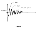
- the figure 3 illustrates this mode of operation by presenting two excitation responses S1 (T1) and S2 (T1) as a function of time. These two excitations are obtained at a first temperature T1.
- the response S1 (T1) is a weakly damped signal indicating that the mark is not under the detector being analyzed.
- this signal S1 (T1) (just like the signal S2 (T1)) is an oscillating signal comprising a plurality of positive and negative lobes; subsequently, we will number the positive lobes from one to one.
- the comparator 12 gives on its output a logic level X equal to 1 indicating that the mark is not under the detector analyzed.
- the comparator 12 gives on its output a logic level X equal to 0 indicating that the mark is under the detector analyzed.
- the means 14 for identifying the passage of the mark at the level of the detectors will memorize this state 0 in a storage device 17 and count a half-turn in a counting device 18. (1 / m turn in the case of m detectors with m greater than or equal to two).
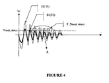
- FIG. figure 4 shows two excitation responses S1 (T1) and S1 (T2) as a function of time. These two excitations are respectively obtained at the first temperature T1 and at a second temperature T2 higher than T1. In both cases, the mark is not under the detector being analyzed.
- the signal S1 (T2) is always below the signal S1 (T1); by making a comparison on the observation window F_Nseuil_etect previously defined, the amplitude of the signal S1 (T2) is already below the threshold Vseuil_detect while it is known that the mark is not under the detector. Therefore, it is important to be able to reset F_Nseuil_detect so as to obtain a coherent result. For this, the second switch 19 is switched to its second position 191.
- the second switch 19 is switched to its second position 191, the control means 23 can shift the observation window to the left along the dashed arrow (by decreasing the lobe number one by one) to obtain a window F_Nmax (corresponding to the lobe placed at the Nmax position) for which the amplitude of the signal S1 (T2) goes back above the voltage Vseuil_detect.
- This window F_Nmax is determined by an observation window search device 15 informed by the passage of X from 0 to 1.
- Nseuil_detect defines a new observation window F_Nseuil_mütect for which it is certain that the device 10 will not detect the presence of the mark when it is not under the detector to be analyzed.
- the computing device 16 transmits this new F_Nseuil_detect value to the control means 21 which will use this new value during subsequent detections.
- the reset principle will be the same if the amplitude of the signal of the analyzed detector increases (case of a decrease of temperature); in this case, it will be necessary to search for the new maximum positive lobe so that the amplitude of the signal is above the comparison voltage Vseuil_convergetect fixed.
- reset means 13 may for example be made using software means via the programming of a microprocessor.
- the value of the logic level X is advantageously used to both count the number of revolutions and reset the device in case of variation of certain parameters such as temperature.
- the reset is performed here by varying the observation window and keeping a comparison voltage Vseuil_détect fixed.
- Vseuil_detect a comparison voltage
- the calibration of the detectors can be done either every 1 / m of a turn in the case of m detectors, that is to say at each detection of the mark but it can also be performed at a more relaxed time depending on the variation of the influence parameters, the latter being able to vary relatively slowly.
- the figure 6 represents a device 100 for detecting the rotation of a rotating element according to a second embodiment of the invention.
- the device 100 may for example be used with the detection system of the figure 1 and makes it possible to detect the rotation of the disc 2 integral with the turbine 1.
- the figure 1 we will make the assumption here that the disk is provided with an eccentric mark with respect to the axis XX 'and likely to modify the amplitude response of proximity sensors when the disk is rotated.
- the excitation circuit 101 makes it possible to excite the two detectors L0 and L1 at the same time and to output a voltage Vc corresponding to the excitation response of one of the detectors L0 or L1.
- the switch 120 makes it possible to supply on the positive input of the comparator 102 the excitation response of one of the two detectors L0 or L1.
- this voltage Vc is compared with a reference voltage Vseuil_detect provided by a generator 122.
- This reference voltage Vseuil_detect is injected on the negative input of the comparator 102.
- figure 7 illustrates this mode of operation by presenting two excitation responses S'1 (T1) and S'2 (T1) as a function of time. These two excitations are obtained at a first temperature T1.
- the response S'1 (T1) is a weakly damped signal indicating that the mark is not under the detector analyzed.
- this signal S'1 (T1) (just like the signal S'2 (T1)) is an oscillating signal comprising a plurality of positive and negative lobes; subsequently, we will number the positive lobes from one to one.
- the comparator 102 gives on its output a logical level X equal to 1 indicating that the mark is not under the detector analyzed.
- the comparator 102 gives on its output a logic level X equal to 0 indicating that the mark is under the detector analyzed.
- the means 104 for identifying the passage of the mark at the level of the detectors will memorize this state 0 in a storage device 107 and count a half-turn in a counting device 108. (1 / m turn in the case of m detectors with m greater than or equal to two).
- FIG. figure 8 shows two excitation responses S'1 (T1) and S'1 (T2) as a function of time. These two excitations are respectively obtained at the first temperature T1 and at a second temperature T2 higher than T1. In both cases, the mark is not under the detector being analyzed.
- the mark is not under the analyzed proximity sensor, for example L0; this information is obtained by the fact that the previous excitation showed that the mark was under the detector L1 (obtaining a level X equal to 0); therefore, during the next excitation, it is certain that the mark is not yet under the detector L0 (the switching time of the switch 120 being chosen much greater than the time taken by the mark to switch from the detector L1 to the detector L0).
- the coil L0 is calibrated because it is certain that L0 is not under the mark for a period of time depending on the speed of rotation of the target and the shape thereof. .
- the second switch 119 has two positions 119a and 119b.
- the normal operating position (excluding reset) is the position 119a for which the negative input of the comparator 102 is connected to Vseuil_detect provided by the generator 122.
- the switch 119 is switched to its second position 119b so that the means 123 allow to inject a variable voltage Vvar on the negative input of the comparator 102 and thus to decrease the voltage Vseuil_detect initially on the input negative to a voltage Vmax for which the amplitude of the signal S'1 (T2) goes back above the voltage Vmax.
- This voltage Vmax is determined by the voltage search device 105 informed by the passage of X from 0 to 1.
- Vvar is decremented until a logic 1 is obtained.
- the computing device 106 transmits this new Vseuil_detect value to the generator 122 which will use this new value during the following detections.
- the device 100 will not detect the presence of the mark when it is not under the detector to be analyzed.
- window F_Nseuil_detect also corresponds to the feeding time of the means 123. Such a power supply reduces consumption.
- the reset is done by successive approximation by varying the value of a parameter and interpreting the binary information of the logic level X.
- Vmax is sought according to the method described above and this value is compared with respect to the preceding voltage Vmax. If the new value of Vmax is greater than the previous Vmax, then this new value of Vmax must be taken into account. Indeed, if the amplitude of the detectors has increased, even if the detector is opposite the mark, we can take into account the new value of Vmax if it is greater than the value previous, which will allow the system to not lose a turn when the brand will start turning again in the presence of a flow of fluid.
- calculation means have been described as software means programmed on a microprocessor but they can also be made using hardware means.
Landscapes
- Physics & Mathematics (AREA)
- Fluid Mechanics (AREA)
- General Physics & Mathematics (AREA)
- Measuring Volume Flow (AREA)
- Transmission And Conversion Of Sensor Element Output (AREA)
- Investigating Or Analyzing Materials By The Use Of Electric Means (AREA)
- Control Of Eletrric Generators (AREA)
Claims (13)
- Vorrichtung (10, 100) zur Detektion der Rotation eines Elements, das um eine Achse XX' rotiert, die umfasst:- m Näherungsdetektoren (L0, L1), die sich in einer Ebene senkrecht zur Achse XX' gemäß m radialer Richtungen befinden, wobei m eine Ganzzahl größer oder gleich 2 ist, wobei eine Marke mit dem rotierenden Element verbunden ist und exzentriert im Verhältnis zur Achse XX' und imstande, die Amplitudenantwort der Näherungsdetektoren zu ändern, wenn sich das rotierende Element in einer Rotationsbewegung befindet,- einen Erregerkreis (11, 101), der dazu bestimmt ist, die Näherungsdektoren zu erregen, wobei jeder Detektoren eine Erregungsantwort liefert, wenn er erregt ist, wobei die Vorrichtung (10, 100) dadurch gekennzeichnet ist, dass sie aufweist:- Vergleichsmittel (12, 102) der Amplitude der Erregungsantwort jedes Detektors (L0, L1) mit einem Vergleichsgrenzwert während einer als Beobachtungsfenster genannten Zeitperiode und um ein logisches Niveau 1 oder 0 zu liefern, je nachdem, ob die Antwortamplitude größer oder kleiner als der Vergleichsgrenzwert ist,- Mittel (14, 104), um den Übergang der Marke auf Ebene einer der Detektoren (L0, L1) in Abhängigkeit vom Wert 0 oder 1 des logischen Niveaus zu identifizieren,- Reinitialisierungsmittel (13, 103), um entweder den Vergleichsgrenzwert oder das Beobachtungsfenster als Merkmale eines Detektors (L0, L1) zu ändern, sobald die Vergleichsmittel (12, 102) ein logisches Niveau liefern, das für den Übergang der Marke auf die Ebene des Detektors repräsentativ ist, während die Marke nicht auf Ebene des Detektors (L0, L1 sein kann, wobei die Reinitialisierung darin besteht, durch aufeinanderfolgende Iterationen entweder einen neuen Vergleichsgrenzwert oder ein neues Beobachtungsfenster zu suchen, wofür die Vergleichswerte (12, 102) ein logisches Niveau liefern, das für die Abwesenheit des Übergangs der Marke auf Ebene des Detektors repräsentativ ist.
- Vorrichtung (10, 100) nach Anspruch 1, dadurch gekennzeichnet, dass das rotierende Element aus nichtmetallischem Werkstoff ist und die Marke von einem metallisierten Abschnitt des rotierenden Elements gebildet wird.
- Vorrichtung (10, 100) nach Anspruch 1 oder 2, dadurch gekennzeichnet, dass jeder Näherungsdetektor ein Schwingkreis ist und der Erregerkreis einen Impulsgeber umfasst, der aufeinanderfolgend jeden Detektor derart versorgt, dass die Erregungsantwort jedes Detektors ein mehr oder weniger gedämpftes Schwingsignal ist, je nachdem, ob die Marke auf Ebene des Detektors ist oder nicht, wobei das Signal eine Abfolge von positiven und negativen Scheiteln einer abnehmenden Amplitude aufweist, wobei jeder Scheitel aufeinanderfolgend nummerierbar ist.
- Vorrichtung (10, 100) nach Anspruch 3, dadurch gekennzeichnet, dass die Dauer des Beobachtungsfensters etwa der Dauer eines bestimmten Scheitels der Erregungsantwort entspricht.
- Vorrichtung (10, 100) nach einem der Ansprüche 3 oder 4, dadurch gekennzeichnet, dass die Frequenz des Impulsgebers zwischen 50 und 500 Hz angesiedelt ist.
- Vorrichtung (10, 100) nach einem der Ansprüche 3 bis 5, dadurch gekennzeichnet, dass die Erregungsantwort jedes Detektors eine Frequenz von zirka gleich 250 kHz hat.
- Vorrichtung (100) nach einem der Ansprüche 1 bis 6, dadurch gekennzeichnet, dass die Vergleichsmittel (102) geeignet sind, um einen variablen Vergleichsgrenzwert (Vvar) zu empfangen, so dass die Amplitude der Erregungsantwort jedes Detektors (L0, L1) mit dem variablen Vergleichsgrenzwert (Vvar) vergleichbar ist, wobei die Reinitialisierungsmittel (103) aufweisen:- Bestimmungsmittel (105) durch aufeinanderfolgende Iterationen, für ein vorbestimmtes Beobachtungsfenster, der Amplitude der Erregungsantwort eines Detektors, wenn die Marke nicht auf Ebene des Detektors sein kann, durch Nutzung des Übergangs von einem logischen Zustand in den anderen des logischen Niveaus, das aus dem Vergleich der Amplitude der Erregungsantwort mit dem variablen Vergleichsgrenzwert hervorgegangen ist,- Mittel (106), um den Vergleichsgrenzwert auf einen Wert zu kalibrieren, der von der von den Bestimmungsmitteln (105) bestimmten Amplitude der Erregungsantwort abhängt.
- Vorrichtung (10) nach einem der Ansprüche 4 bis 6, dadurch gekennzeichnet, dass das Beobachtungsfenster je nach ausgewähltem Scheitel änderbar ist, so dass die Vergleichsmittel (12) geeignet sind, um einen Vergleich für ein Beobachtungsfenster durchzuführen, das zeitlich in Abhängigkeit von der Nummer des ausgewählten Scheitels versetzt ist.
- Vorrichtung (10) nach Anspruch 8, dadurch gekennzeichnet, dass die Reinititalisierungsmittel aufweisen:- Bestimmungsmittel (15) durch aufeinanderfolgende Iterationen, für einen festgelegten Vergleichsgrenzwert, der Nummer des Scheitels der Erregungsantwort eines Detektors (L0, L1), wenn die Marke nicht auf Ebene des Detektors sein kann, durch Nutzung des Übergangs eines logischen Zustands in den anderen des logischen Niveaus, das aus dem Vergleich der Amplitude der Erregungsantwort mit dem festgelegten Vergleichsgrenzwert hervorgegangen ist, wenn sich die Scheitelnummer ändert,- Mittel zum Kalibrieren (16) des Beobachtungsfensters auf einen Wert, der von der von den Bestimmungsmitteln (15) bestimmten Scheitelnummer abhängt.
- Vorrichtung (10, 100) nach einem der vorangehenden Ansprüche, dadurch gekennzeichnet, dass das rotierende Element eine mit der Turbine eines Wasserzählers verbundene Scheibe umfasst, wobei der Wasserzähler in ein Kalorimeter integrierbar ist, das zur Abrechnung der von einem Warmwasserkreis gelieferten Energie bestimmt ist.
- Vorrichtung (10, 100) nach einem der vorangehenden Ansprüche, dadurch gekennzeichnet, dass der Vergleichsgrenzwert ein Spannungswert ist.
- Vorrichtung nach einem der vorangehenden Ansprüche, dadurch gekennzeichnet, dass sie aufweist:- mindestens drei Näherungsdetektoren (L0, L1, L2),- Mittel zur Bestimmung der Rotationsrichtung des rotierenden Elements.
- Vorrichtung nach einem der vorangehenden Ansprüche, dadurch gekennzeichnet, dass die Reinitialisierungsmittel (13, 103) bei Abwesenheit einer Rotation des rotierenden Elements funktionieren.
Applications Claiming Priority (2)
| Application Number | Priority Date | Filing Date | Title |
|---|---|---|---|
| FR0351240A FR2864615B1 (fr) | 2003-12-31 | 2003-12-31 | Dispositif de detection d'un element tournant tel que la turbine d'un compteur d'eau |
| FR0351240 | 2003-12-31 |
Publications (2)
| Publication Number | Publication Date |
|---|---|
| EP1550844A1 EP1550844A1 (de) | 2005-07-06 |
| EP1550844B1 true EP1550844B1 (de) | 2012-02-29 |
Family
ID=34566401
Family Applications (1)
| Application Number | Title | Priority Date | Filing Date |
|---|---|---|---|
| EP04300958A Expired - Lifetime EP1550844B1 (de) | 2003-12-31 | 2004-12-31 | Einrichtung zur Detektion des Drehens eines rotierenden Elements, wie einer Wasserzählerturbine |
Country Status (6)
| Country | Link |
|---|---|
| US (1) | US7106054B2 (de) |
| EP (1) | EP1550844B1 (de) |
| CN (1) | CN1651866A (de) |
| AT (1) | ATE547691T1 (de) |
| ES (1) | ES2386009T3 (de) |
| FR (1) | FR2864615B1 (de) |
Families Citing this family (7)
| Publication number | Priority date | Publication date | Assignee | Title |
|---|---|---|---|---|
| WO2006129349A1 (ja) * | 2005-05-31 | 2006-12-07 | Fujitsu Limited | データ受信装置 |
| FR3025309B1 (fr) * | 2014-08-28 | 2018-03-16 | Sagemcom Energy & Telecom Sas | Dispositif de comptage de tours d`une roue au moyen d`une bobine et compteur equipe de ce dispositif de comptage |
| FR3026839B1 (fr) * | 2014-10-03 | 2016-11-04 | Sagemcom Energy & Telecom Sas | Procede d'auto-calibration d'un dispositif de comptage de tours d'une roue |
| FR3027105B1 (fr) * | 2014-10-13 | 2018-02-16 | Sagemcom Energy & Telecom Sas | Procede d'auto-calibration d'un dispositif de comptage de tours d'une roue par ajustement d'une tension de reference |
| EP3401648A1 (de) | 2017-05-09 | 2018-11-14 | Aiut Sp. z o.o. | Mechanisches trommelzählwerk für verbrauchsmesser |
| CN107576336B (zh) * | 2017-08-29 | 2020-05-26 | 重庆智慧水务有限公司 | 一种无磁传感器 |
| FR3131957B1 (fr) * | 2022-01-17 | 2024-01-05 | St Microelectronics Grenoble 2 | Excitation et lecture d'un réseau d'oscillateurs LC |
Family Cites Families (4)
| Publication number | Priority date | Publication date | Assignee | Title |
|---|---|---|---|---|
| FR2664973B1 (fr) * | 1990-07-20 | 1992-10-23 | Schlumberger Ind Sa | Dispositif de detection de rotation d'un element tournant tel que la turbine d'un compteur d'eau. |
| DE4137695C2 (de) * | 1991-11-15 | 1994-12-01 | Texas Instruments Deutschland | Sensoranordnung zur Feststellung des Bewegungszustandes eines Rotors |
| US5450760A (en) * | 1993-10-18 | 1995-09-19 | Lew; Hyok S. | Turbine flowmeter with capacitive transducer |
| US6012339A (en) * | 1997-03-31 | 2000-01-11 | Lake Monitors, Inc. | Tangential rotor flow rate meter |
-
2003
- 2003-12-31 FR FR0351240A patent/FR2864615B1/fr not_active Expired - Fee Related
-
2004
- 2004-12-22 US US11/020,637 patent/US7106054B2/en not_active Expired - Fee Related
- 2004-12-31 ES ES04300958T patent/ES2386009T3/es not_active Expired - Lifetime
- 2004-12-31 CN CN200410075871.6A patent/CN1651866A/zh active Pending
- 2004-12-31 AT AT04300958T patent/ATE547691T1/de active
- 2004-12-31 EP EP04300958A patent/EP1550844B1/de not_active Expired - Lifetime
Also Published As
| Publication number | Publication date |
|---|---|
| US20050140364A1 (en) | 2005-06-30 |
| CN1651866A (zh) | 2005-08-10 |
| FR2864615A1 (fr) | 2005-07-01 |
| ES2386009T3 (es) | 2012-08-07 |
| US7106054B2 (en) | 2006-09-12 |
| ATE547691T1 (de) | 2012-03-15 |
| EP1550844A1 (de) | 2005-07-06 |
| FR2864615B1 (fr) | 2006-03-10 |
Similar Documents
| Publication | Publication Date | Title |
|---|---|---|
| EP0467753B1 (de) | Einrichtung zur Detektion des Drehens eines rotierenden Elements, wie zum Beispiel einer Wasserzählerturbine | |
| EP2496914B1 (de) | Bidirektionaler magnetischer positionssensor mit rotierendem magnetfeld | |
| CA2728491C (fr) | Procede et systeme de determination de la position angulaire d'un rotor de turboreacteur | |
| WO2017088968A1 (fr) | Procede de calibration automatique d'un capteur d'arbre a cames pour moteur de vehicule automobile | |
| FR2978833A1 (fr) | Procede de calibration automatique d'un capteur d'arbre a cames pour vehicule automobile | |
| FR3029283A1 (fr) | Capteur d'arbre a came ou de vilebrequin pour vehicule automobile et procede de diagnostic d'un tel capteur | |
| EP0734510B1 (de) | Verfahren und vorrichtung zur überwachung der entwicklung des aktuellen strömungswertes in einem zähler | |
| EP1550844B1 (de) | Einrichtung zur Detektion des Drehens eines rotierenden Elements, wie einer Wasserzählerturbine | |
| FR3041426A1 (fr) | Procede de calibration automatique d'un capteur d'arbre a cames pour moteur de vehicule automobile | |
| FR2915773A1 (fr) | Procede et dispositif de surveillance d'un turbocompresseur de gaz d'echappement equipant un moteur a combustion interne | |
| FR2470386A1 (fr) | Capteur de vitesse de rotation ou d'angle de rotation avec montage d'exploitation associe | |
| CH678985A5 (de) | ||
| EP0952426A1 (de) | Uhrwerk mit einem induktiven oder kapazitiven Sensor zur Detektion von mindestens einem Drehwinkel eines Zahnrades innerhalb des Uhrwerkes | |
| EP1194999B1 (de) | Verfahren zur feststellung eines elektrischen mehrphasenschrittmotors | |
| FR3069636B1 (fr) | Procede et dispositif de detection d'une inversion d'un capteur vilebrequin | |
| FR2880682A1 (fr) | Capteur de position a rapport cyclique desequilibre | |
| EP1756526B1 (de) | Einrichtung und verfahren zur bestimmung der position eines motors | |
| EP4042113B1 (de) | Verfahren zur erkennung einer absoluten winkelposition oder eines absoluten winkelverlagerungshubes eines drehenden organs | |
| FR2921480A1 (fr) | Capteur de position absolue a lecture serie | |
| FR3027103A1 (fr) | Ensemble de capteur de position angulaire pour moteur hybride de vehicule automobile a arbre commun | |
| FR3142249A1 (fr) | Procédé de détermination de la position angulaire d’un arbre de véhicule automobile | |
| FR3069635B1 (fr) | Procede de calibration automatique d'un capteur d'arbre a cames pour moteur de vehicule automobile | |
| FR2696233A1 (fr) | Capteur incrémental à signalisation de défaillance. | |
| CH710522A2 (fr) | Appareil électromécanique comportant un dispositif de détection capacitif de la position angulaire d'un mobile, et procédé de détection de la position angulaire d'un mobile. | |
| FR2593290A1 (fr) | Detecteur de vitesse et de sens de rotation pour machine tournante |
Legal Events
| Date | Code | Title | Description |
|---|---|---|---|
| PUAI | Public reference made under article 153(3) epc to a published international application that has entered the european phase |
Free format text: ORIGINAL CODE: 0009012 |
|
| AK | Designated contracting states |
Kind code of ref document: A1 Designated state(s): AT BE BG CH CY CZ DE DK EE ES FI FR GB GR HU IE IS IT LI LT LU MC NL PL PT RO SE SI SK TR |
|
| AX | Request for extension of the european patent |
Extension state: AL BA HR LV MK YU |
|
| 17P | Request for examination filed |
Effective date: 20060109 |
|
| AKX | Designation fees paid |
Designated state(s): AT BE BG CH CY CZ DE DK EE ES FI FR GB GR HU IE IS IT LI LT LU MC NL PL PT RO SE SI SK TR |
|
| 17Q | First examination report despatched |
Effective date: 20091013 |
|
| GRAP | Despatch of communication of intention to grant a patent |
Free format text: ORIGINAL CODE: EPIDOSNIGR1 |
|
| GRAS | Grant fee paid |
Free format text: ORIGINAL CODE: EPIDOSNIGR3 |
|
| GRAA | (expected) grant |
Free format text: ORIGINAL CODE: 0009210 |
|
| AK | Designated contracting states |
Kind code of ref document: B1 Designated state(s): AT BE BG CH CY CZ DE DK EE ES FI FR GB GR HU IE IS IT LI LT LU MC NL PL PT RO SE SI SK TR |
|
| RAP1 | Party data changed (applicant data changed or rights of an application transferred) |
Owner name: ITRON FRANCE |
|
| REG | Reference to a national code |
Ref country code: GB Ref legal event code: FG4D Free format text: NOT ENGLISH Ref country code: CH Ref legal event code: EP |
|
| REG | Reference to a national code |
Ref country code: DE Ref legal event code: R081 Ref document number: 602004036691 Country of ref document: DE Owner name: ITRON GLOBAL SARL, LIBERTY LAKE, US Free format text: FORMER OWNER: ACTARIS S.A.S., BOULOGNE, FR |
|
| REG | Reference to a national code |
Ref country code: AT Ref legal event code: REF Ref document number: 547691 Country of ref document: AT Kind code of ref document: T Effective date: 20120315 |
|
| REG | Reference to a national code |
Ref country code: IE Ref legal event code: FG4D Free format text: LANGUAGE OF EP DOCUMENT: FRENCH |
|
| REG | Reference to a national code |
Ref country code: DE Ref legal event code: R096 Ref document number: 602004036691 Country of ref document: DE Effective date: 20120426 |
|
| REG | Reference to a national code |
Ref country code: NL Ref legal event code: VDEP Effective date: 20120229 |
|
| LTIE | Lt: invalidation of european patent or patent extension |
Effective date: 20120229 |
|
| PG25 | Lapsed in a contracting state [announced via postgrant information from national office to epo] |
Ref country code: LT Free format text: LAPSE BECAUSE OF FAILURE TO SUBMIT A TRANSLATION OF THE DESCRIPTION OR TO PAY THE FEE WITHIN THE PRESCRIBED TIME-LIMIT Effective date: 20120229 Ref country code: NL Free format text: LAPSE BECAUSE OF FAILURE TO SUBMIT A TRANSLATION OF THE DESCRIPTION OR TO PAY THE FEE WITHIN THE PRESCRIBED TIME-LIMIT Effective date: 20120229 Ref country code: IS Free format text: LAPSE BECAUSE OF FAILURE TO SUBMIT A TRANSLATION OF THE DESCRIPTION OR TO PAY THE FEE WITHIN THE PRESCRIBED TIME-LIMIT Effective date: 20120629 |
|
| REG | Reference to a national code |
Ref country code: ES Ref legal event code: FG2A Ref document number: 2386009 Country of ref document: ES Kind code of ref document: T3 Effective date: 20120807 |
|
| PG25 | Lapsed in a contracting state [announced via postgrant information from national office to epo] |
Ref country code: FI Free format text: LAPSE BECAUSE OF FAILURE TO SUBMIT A TRANSLATION OF THE DESCRIPTION OR TO PAY THE FEE WITHIN THE PRESCRIBED TIME-LIMIT Effective date: 20120229 Ref country code: PT Free format text: LAPSE BECAUSE OF FAILURE TO SUBMIT A TRANSLATION OF THE DESCRIPTION OR TO PAY THE FEE WITHIN THE PRESCRIBED TIME-LIMIT Effective date: 20120629 Ref country code: GR Free format text: LAPSE BECAUSE OF FAILURE TO SUBMIT A TRANSLATION OF THE DESCRIPTION OR TO PAY THE FEE WITHIN THE PRESCRIBED TIME-LIMIT Effective date: 20120530 |
|
| REG | Reference to a national code |
Ref country code: AT Ref legal event code: MK05 Ref document number: 547691 Country of ref document: AT Kind code of ref document: T Effective date: 20120229 |
|
| REG | Reference to a national code |
Ref country code: IE Ref legal event code: FD4D |
|
| PG25 | Lapsed in a contracting state [announced via postgrant information from national office to epo] |
Ref country code: CY Free format text: LAPSE BECAUSE OF FAILURE TO SUBMIT A TRANSLATION OF THE DESCRIPTION OR TO PAY THE FEE WITHIN THE PRESCRIBED TIME-LIMIT Effective date: 20120229 |
|
| PG25 | Lapsed in a contracting state [announced via postgrant information from national office to epo] |
Ref country code: SE Free format text: LAPSE BECAUSE OF FAILURE TO SUBMIT A TRANSLATION OF THE DESCRIPTION OR TO PAY THE FEE WITHIN THE PRESCRIBED TIME-LIMIT Effective date: 20120229 Ref country code: DK Free format text: LAPSE BECAUSE OF FAILURE TO SUBMIT A TRANSLATION OF THE DESCRIPTION OR TO PAY THE FEE WITHIN THE PRESCRIBED TIME-LIMIT Effective date: 20120229 Ref country code: RO Free format text: LAPSE BECAUSE OF FAILURE TO SUBMIT A TRANSLATION OF THE DESCRIPTION OR TO PAY THE FEE WITHIN THE PRESCRIBED TIME-LIMIT Effective date: 20120229 Ref country code: SI Free format text: LAPSE BECAUSE OF FAILURE TO SUBMIT A TRANSLATION OF THE DESCRIPTION OR TO PAY THE FEE WITHIN THE PRESCRIBED TIME-LIMIT Effective date: 20120229 Ref country code: PL Free format text: LAPSE BECAUSE OF FAILURE TO SUBMIT A TRANSLATION OF THE DESCRIPTION OR TO PAY THE FEE WITHIN THE PRESCRIBED TIME-LIMIT Effective date: 20120229 Ref country code: EE Free format text: LAPSE BECAUSE OF FAILURE TO SUBMIT A TRANSLATION OF THE DESCRIPTION OR TO PAY THE FEE WITHIN THE PRESCRIBED TIME-LIMIT Effective date: 20120229 Ref country code: CZ Free format text: LAPSE BECAUSE OF FAILURE TO SUBMIT A TRANSLATION OF THE DESCRIPTION OR TO PAY THE FEE WITHIN THE PRESCRIBED TIME-LIMIT Effective date: 20120229 Ref country code: IE Free format text: LAPSE BECAUSE OF FAILURE TO SUBMIT A TRANSLATION OF THE DESCRIPTION OR TO PAY THE FEE WITHIN THE PRESCRIBED TIME-LIMIT Effective date: 20120229 |
|
| PG25 | Lapsed in a contracting state [announced via postgrant information from national office to epo] |
Ref country code: SK Free format text: LAPSE BECAUSE OF FAILURE TO SUBMIT A TRANSLATION OF THE DESCRIPTION OR TO PAY THE FEE WITHIN THE PRESCRIBED TIME-LIMIT Effective date: 20120229 |
|
| PLBE | No opposition filed within time limit |
Free format text: ORIGINAL CODE: 0009261 |
|
| STAA | Information on the status of an ep patent application or granted ep patent |
Free format text: STATUS: NO OPPOSITION FILED WITHIN TIME LIMIT |
|
| PG25 | Lapsed in a contracting state [announced via postgrant information from national office to epo] |
Ref country code: AT Free format text: LAPSE BECAUSE OF FAILURE TO SUBMIT A TRANSLATION OF THE DESCRIPTION OR TO PAY THE FEE WITHIN THE PRESCRIBED TIME-LIMIT Effective date: 20120229 |
|
| 26N | No opposition filed |
Effective date: 20121130 |
|
| REG | Reference to a national code |
Ref country code: DE Ref legal event code: R097 Ref document number: 602004036691 Country of ref document: DE Effective date: 20121130 |
|
| BERE | Be: lapsed |
Owner name: ITRON FRANCE Effective date: 20121231 |
|
| PG25 | Lapsed in a contracting state [announced via postgrant information from national office to epo] |
Ref country code: BG Free format text: LAPSE BECAUSE OF FAILURE TO SUBMIT A TRANSLATION OF THE DESCRIPTION OR TO PAY THE FEE WITHIN THE PRESCRIBED TIME-LIMIT Effective date: 20120529 Ref country code: MC Free format text: LAPSE BECAUSE OF NON-PAYMENT OF DUE FEES Effective date: 20121231 |
|
| REG | Reference to a national code |
Ref country code: CH Ref legal event code: PL |
|
| GBPC | Gb: european patent ceased through non-payment of renewal fee |
Effective date: 20121231 |
|
| REG | Reference to a national code |
Ref country code: FR Ref legal event code: ST Effective date: 20130830 |
|
| PG25 | Lapsed in a contracting state [announced via postgrant information from national office to epo] |
Ref country code: BE Free format text: LAPSE BECAUSE OF NON-PAYMENT OF DUE FEES Effective date: 20121231 |
|
| REG | Reference to a national code |
Ref country code: DE Ref legal event code: R119 Ref document number: 602004036691 Country of ref document: DE Effective date: 20130702 |
|
| PG25 | Lapsed in a contracting state [announced via postgrant information from national office to epo] |
Ref country code: DE Free format text: LAPSE BECAUSE OF NON-PAYMENT OF DUE FEES Effective date: 20130702 Ref country code: CH Free format text: LAPSE BECAUSE OF NON-PAYMENT OF DUE FEES Effective date: 20121231 Ref country code: LI Free format text: LAPSE BECAUSE OF NON-PAYMENT OF DUE FEES Effective date: 20121231 |
|
| REG | Reference to a national code |
Ref country code: DE Ref legal event code: R073 Ref document number: 602004036691 Country of ref document: DE |
|
| PG25 | Lapsed in a contracting state [announced via postgrant information from national office to epo] |
Ref country code: FR Free format text: LAPSE BECAUSE OF NON-PAYMENT OF DUE FEES Effective date: 20130102 Ref country code: GB Free format text: LAPSE BECAUSE OF NON-PAYMENT OF DUE FEES Effective date: 20121231 |
|
| REG | Reference to a national code |
Ref country code: DE Ref legal event code: R074 Ref document number: 602004036691 Country of ref document: DE |
|
| PG25 | Lapsed in a contracting state [announced via postgrant information from national office to epo] |
Ref country code: IT Free format text: LAPSE BECAUSE OF NON-PAYMENT OF DUE FEES Effective date: 20121231 |
|
| REG | Reference to a national code |
Ref country code: DE Ref legal event code: R074 Ref document number: 602004036691 Country of ref document: DE Effective date: 20131202 Ref country code: DE Ref legal event code: R074 Ref document number: 602004036691 Country of ref document: DE Effective date: 20131205 |
|
| PGRI | Patent reinstated in contracting state [announced from national office to epo] |
Ref country code: DE Effective date: 20131202 |
|
| PGFP | Annual fee paid to national office [announced via postgrant information from national office to epo] |
Ref country code: IT Payment date: 20131223 Year of fee payment: 10 |
|
| PGRI | Patent reinstated in contracting state [announced from national office to epo] |
Ref country code: IT Effective date: 20140101 |
|
| REG | Reference to a national code |
Ref country code: GB Ref legal event code: S28 Free format text: APPLICATION FILED |
|
| PG25 | Lapsed in a contracting state [announced via postgrant information from national office to epo] |
Ref country code: TR Free format text: LAPSE BECAUSE OF FAILURE TO SUBMIT A TRANSLATION OF THE DESCRIPTION OR TO PAY THE FEE WITHIN THE PRESCRIBED TIME-LIMIT Effective date: 20120229 |
|
| PG25 | Lapsed in a contracting state [announced via postgrant information from national office to epo] |
Ref country code: LU Free format text: LAPSE BECAUSE OF NON-PAYMENT OF DUE FEES Effective date: 20121231 |
|
| REG | Reference to a national code |
Ref country code: GB Ref legal event code: S28 Free format text: RESTORATION ALLOWED Effective date: 20140509 |
|
| PG25 | Lapsed in a contracting state [announced via postgrant information from national office to epo] |
Ref country code: HU Free format text: LAPSE BECAUSE OF FAILURE TO SUBMIT A TRANSLATION OF THE DESCRIPTION OR TO PAY THE FEE WITHIN THE PRESCRIBED TIME-LIMIT Effective date: 20041231 |
|
| PGFP | Annual fee paid to national office [announced via postgrant information from national office to epo] |
Ref country code: GB Payment date: 20140321 Year of fee payment: 10 |
|
| GBPC | Gb: european patent ceased through non-payment of renewal fee |
Effective date: 20141231 |
|
| PG25 | Lapsed in a contracting state [announced via postgrant information from national office to epo] |
Ref country code: GB Free format text: LAPSE BECAUSE OF NON-PAYMENT OF DUE FEES Effective date: 20141231 |
|
| PG25 | Lapsed in a contracting state [announced via postgrant information from national office to epo] |
Ref country code: IT Free format text: LAPSE BECAUSE OF NON-PAYMENT OF DUE FEES Effective date: 20141231 |
|
| REG | Reference to a national code |
Ref country code: DE Ref legal event code: R081 Ref document number: 602004036691 Country of ref document: DE Owner name: ITRON GLOBAL SARL, LIBERTY LAKE, US Free format text: FORMER OWNER: ITRON FRANCE, ISSY-LES-MOULINEAUX, FR Ref country code: DE Ref legal event code: R082 Ref document number: 602004036691 Country of ref document: DE Representative=s name: GROSSE, SCHUMACHER, KNAUER, VON HIRSCHHAUSEN, DE |
|
| REG | Reference to a national code |
Ref country code: ES Ref legal event code: PC2A Owner name: ITRON GLOBAL SARL Effective date: 20170130 |
|
| PGFP | Annual fee paid to national office [announced via postgrant information from national office to epo] |
Ref country code: DE Payment date: 20211109 Year of fee payment: 18 |
|
| PGFP | Annual fee paid to national office [announced via postgrant information from national office to epo] |
Ref country code: ES Payment date: 20220104 Year of fee payment: 18 |
|
| REG | Reference to a national code |
Ref country code: DE Ref legal event code: R119 Ref document number: 602004036691 Country of ref document: DE |
|
| PG25 | Lapsed in a contracting state [announced via postgrant information from national office to epo] |
Ref country code: DE Free format text: LAPSE BECAUSE OF NON-PAYMENT OF DUE FEES Effective date: 20230701 |
|
| REG | Reference to a national code |
Ref country code: ES Ref legal event code: FD2A Effective date: 20240202 |
|
| PG25 | Lapsed in a contracting state [announced via postgrant information from national office to epo] |
Ref country code: ES Free format text: LAPSE BECAUSE OF NON-PAYMENT OF DUE FEES Effective date: 20230101 |
|
| PG25 | Lapsed in a contracting state [announced via postgrant information from national office to epo] |
Ref country code: ES Free format text: LAPSE BECAUSE OF NON-PAYMENT OF DUE FEES Effective date: 20230101 |