EP1550844B1 - Device for detecting the movement of a rotating element, such as the turbine in a water meter - Google Patents
Device for detecting the movement of a rotating element, such as the turbine in a water meter Download PDFInfo
- Publication number
- EP1550844B1 EP1550844B1 EP04300958A EP04300958A EP1550844B1 EP 1550844 B1 EP1550844 B1 EP 1550844B1 EP 04300958 A EP04300958 A EP 04300958A EP 04300958 A EP04300958 A EP 04300958A EP 1550844 B1 EP1550844 B1 EP 1550844B1
- Authority
- EP
- European Patent Office
- Prior art keywords
- detector
- mark
- comparison
- detectors
- amplitude
- Prior art date
- Legal status (The legal status is an assumption and is not a legal conclusion. Google has not performed a legal analysis and makes no representation as to the accuracy of the status listed.)
- Not-in-force
Links
- XLYOFNOQVPJJNP-UHFFFAOYSA-N water Substances O XLYOFNOQVPJJNP-UHFFFAOYSA-N 0.000 title claims description 12
- 230000033001 locomotion Effects 0.000 title description 5
- 230000005284 excitation Effects 0.000 claims abstract description 53
- 230000003247 decreasing effect Effects 0.000 claims description 3
- 239000000463 material Substances 0.000 claims description 2
- 230000007704 transition Effects 0.000 claims 2
- 238000001514 detection method Methods 0.000 description 15
- 238000000034 method Methods 0.000 description 4
- 238000004364 calculation method Methods 0.000 description 3
- 239000012530 fluid Substances 0.000 description 3
- 230000001427 coherent effect Effects 0.000 description 2
- 238000013016 damping Methods 0.000 description 2
- 230000001419 dependent effect Effects 0.000 description 2
- 238000005265 energy consumption Methods 0.000 description 2
- 230000001939 inductive effect Effects 0.000 description 2
- 239000007769 metal material Substances 0.000 description 2
- 230000003044 adaptive effect Effects 0.000 description 1
- 230000032683 aging Effects 0.000 description 1
- 238000004458 analytical method Methods 0.000 description 1
- 230000005540 biological transmission Effects 0.000 description 1
- 239000003990 capacitor Substances 0.000 description 1
- 235000021183 entrée Nutrition 0.000 description 1
- 238000004519 manufacturing process Methods 0.000 description 1
- 238000005259 measurement Methods 0.000 description 1
- 239000002991 molded plastic Substances 0.000 description 1
- 230000010355 oscillation Effects 0.000 description 1
Images


Classifications
-
- G—PHYSICS
- G01—MEASURING; TESTING
- G01F—MEASURING VOLUME, VOLUME FLOW, MASS FLOW OR LIQUID LEVEL; METERING BY VOLUME
- G01F15/00—Details of, or accessories for, apparatus of groups G01F1/00 - G01F13/00 insofar as such details or appliances are not adapted to particular types of such apparatus
- G01F15/06—Indicating or recording devices
Definitions
- the invention relates to a device for detecting rotation of a rotating element such as the turbine of a water meter.
- Most water meters include a mechanical drive totalizer, ie the rotation of the turbine drives, through a mechanical and / or magnetic transmission, the rollers of the counter index.
- the proximity detector may for example be based on an inductive method, in which case the mark will be constituted by a material whose magnetic and / or electrical characteristics different from the rest of the rotating element.
- the figure 1 illustrates such a detection mode.
- the rotating assembly consists of a turbine 1 of a not shown flowmeter and a disc 2 integral with the turbine 1. When a fluid such as water flows, the turbine 1 and the disc 2 are animated with a rotational movement about the axis XX '. The rotational speed of the rotating element is directly related to the instantaneous flow rate of the fluid.
- Two proximity detectors L0 and L1 situated in a plane P perpendicular to the axis XX ', in two radial directions with respect to the axis XX' are sensitive to the proximity of a mark 5 which is integral with the disc 2 and off-center relative to the axis of rotation XX '. It follows that when the rotating element is driven by a rotational movement, the response of proximity sensors L0 and L1 will change according to the position of the mark 5.
- the two proximity sensors L0 and L1 are for example magnetic coils coupled in parallel with capacitors thus forming two oscillating circuits arranged in two opposite radial directions.
- the disc 2 is made of non-metallic material such only molded plastic and the mark 5 is a metallized radial sector of the disc.
- the document DE 41 37 695 A1 describes a device comprising two detectors adjacent to a rotor.
- the rotor comprises two sectors having different magnetic properties.
- the response of each detector to excitation, in particular the damping time makes it possible to determine which sector is close to the detector.
- the damping time is measured in the number of oscillations exceeding a threshold.
- Such a detection system poses certain difficulties; indeed, there is a series of parameters that varies with time. For example, for a water meter integrated in a calorimeter, it is the water temperature that can vary the characteristics of the detector, the supply voltage of the detection circuit, especially when the power supply is via a battery, and the variable distance between the proximity sensor and the rotating element due to the high speed turbine lift. There is also a series of parameters which vary from detector to detector and which are difficult and expensive to control in mass production; for example, for a detector of the inductive type, these are in particular the values of the coil and its quality coefficient, which leads to a calibration of each detector or a sorting.
- the rotation detection device described in this document comprises at least two proximity sensors intended to detect the passage of a mark integral with the rotating element.
- the device performs an analysis of the evolution of the signal delivered by a first detector.
- the index of the number of revolutions is incremented and the second detector is selected, thereby excluding the first detector which has just detected the mark; the parameters intended to study the evolution of the signals of the second detector are then reinitialized and thus an adaptive system is obtained making it possible to overcome the problems related to the variation of the parameters.
- the device of this solution uses a complex electronic circuit therefore entailing not only a relatively long processing time but also a high energy consumption.
- the present invention relates to a device for detecting the rotation of a member rotating about an axis XX 'according to claim 1.
- the reinitialization of the parameters used to identify the passage of a mark at the level of the detectors is based on a search for these parameters by successive approximations from a binary detection information, ie a comparison value with respect to a threshold value.
- the device of the invention provides a simplified system based on the interpretation of a binary information and not on the direct measurement of the parameters. This technique of binary logic by successive approximations saves time and is more suitable for a low power environment, the logic circuits used being relatively simple and low energy consumption.
- said rotating element is made of non-metallic material and said mark is formed by a metallized part of said rotating element.
- each proximity detector is an oscillating circuit and said excitation circuit comprises a pulse generator successively supplying each detector so that the excitation response of each of the detectors is an oscillating signal that is more or less damped according to the mark. is at the level of said detector, said signal having a succession of positive and negative lobes of decreasing amplitude, each lobe being successively numbered.
- the duration of said observation window substantially corresponds to the duration of a determined lobe of said excitation response.
- the frequency of said pulse generator is between 50 and 500 Hz and the excitation response of each of the detectors has a frequency of approximately 250 kHz.
- said observation window may vary according to the chosen lobe so that said comparison means are adapted to perform a comparison on an observation window which is shifted temporally according to the chosen lobe number.
- said rotating element comprises a disc integral with the turbine of a water meter, said water meter being able to be integrated in a calorimeter intended to account for the energy delivered by a hot water circuit.
- said comparison threshold value is a voltage value.
- said reset means operate in the absence of rotation of said rotating element.
- the figure 2 represents a device 10 for detecting the rotation of a rotating element according to a first embodiment of the invention.
- the device 10 can for example be used with the detection system of the figure 1 and makes it possible to detect the rotation of the disc 2 integral with the turbine 1.
- the disk is provided with an eccentric mark with respect to the axis XX 'and capable of modifying the amplitude response of the proximity sensors when the disk is driven by a rotational movement.
- the excitation circuit 11 makes it possible to excite the two detectors L0 and L1 at the same time and to output a voltage Vc corresponding to the excitation response of one of the detectors L0 or L1.
- the switch 20 makes it possible to supply on the positive input of the comparator 12 the excitation response of one of the two detectors L0 or L1.
- this voltage Vc is compared with a reference voltage Vseuil_detect provided by a generator 22.
- This reference voltage Vseuil_detect fixed is injected on the negative input of the comparator 12.
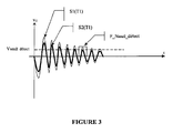
- the figure 3 illustrates this mode of operation by presenting two excitation responses S1 (T1) and S2 (T1) as a function of time. These two excitations are obtained at a first temperature T1.
- the response S1 (T1) is a weakly damped signal indicating that the mark is not under the detector being analyzed.
- this signal S1 (T1) (just like the signal S2 (T1)) is an oscillating signal comprising a plurality of positive and negative lobes; subsequently, we will number the positive lobes from one to one.
- the comparator 12 gives on its output a logic level X equal to 1 indicating that the mark is not under the detector analyzed.
- the comparator 12 gives on its output a logic level X equal to 0 indicating that the mark is under the detector analyzed.
- the means 14 for identifying the passage of the mark at the level of the detectors will memorize this state 0 in a storage device 17 and count a half-turn in a counting device 18. (1 / m turn in the case of m detectors with m greater than or equal to two).
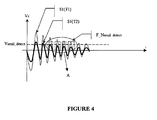
- FIG. figure 4 shows two excitation responses S1 (T1) and S1 (T2) as a function of time. These two excitations are respectively obtained at the first temperature T1 and at a second temperature T2 higher than T1. In both cases, the mark is not under the detector being analyzed.
- the signal S1 (T2) is always below the signal S1 (T1); by making a comparison on the observation window F_Nseuil_etect previously defined, the amplitude of the signal S1 (T2) is already below the threshold Vseuil_detect while it is known that the mark is not under the detector. Therefore, it is important to be able to reset F_Nseuil_detect so as to obtain a coherent result. For this, the second switch 19 is switched to its second position 191.
- the second switch 19 is switched to its second position 191, the control means 23 can shift the observation window to the left along the dashed arrow (by decreasing the lobe number one by one) to obtain a window F_Nmax (corresponding to the lobe placed at the Nmax position) for which the amplitude of the signal S1 (T2) goes back above the voltage Vseuil_detect.
- This window F_Nmax is determined by an observation window search device 15 informed by the passage of X from 0 to 1.
- Nseuil_detect defines a new observation window F_Nseuil_mütect for which it is certain that the device 10 will not detect the presence of the mark when it is not under the detector to be analyzed.
- the computing device 16 transmits this new F_Nseuil_detect value to the control means 21 which will use this new value during subsequent detections.
- the reset principle will be the same if the amplitude of the signal of the analyzed detector increases (case of a decrease of temperature); in this case, it will be necessary to search for the new maximum positive lobe so that the amplitude of the signal is above the comparison voltage Vseuil_convergetect fixed.
- reset means 13 may for example be made using software means via the programming of a microprocessor.
- the value of the logic level X is advantageously used to both count the number of revolutions and reset the device in case of variation of certain parameters such as temperature.
- the reset is performed here by varying the observation window and keeping a comparison voltage Vseuil_détect fixed.
- Vseuil_detect a comparison voltage
- the calibration of the detectors can be done either every 1 / m of a turn in the case of m detectors, that is to say at each detection of the mark but it can also be performed at a more relaxed time depending on the variation of the influence parameters, the latter being able to vary relatively slowly.
- the figure 6 represents a device 100 for detecting the rotation of a rotating element according to a second embodiment of the invention.
- the device 100 may for example be used with the detection system of the figure 1 and makes it possible to detect the rotation of the disc 2 integral with the turbine 1.
- the figure 1 we will make the assumption here that the disk is provided with an eccentric mark with respect to the axis XX 'and likely to modify the amplitude response of proximity sensors when the disk is rotated.
- the excitation circuit 101 makes it possible to excite the two detectors L0 and L1 at the same time and to output a voltage Vc corresponding to the excitation response of one of the detectors L0 or L1.
- the switch 120 makes it possible to supply on the positive input of the comparator 102 the excitation response of one of the two detectors L0 or L1.
- this voltage Vc is compared with a reference voltage Vseuil_detect provided by a generator 122.
- This reference voltage Vseuil_detect is injected on the negative input of the comparator 102.
- figure 7 illustrates this mode of operation by presenting two excitation responses S'1 (T1) and S'2 (T1) as a function of time. These two excitations are obtained at a first temperature T1.
- the response S'1 (T1) is a weakly damped signal indicating that the mark is not under the detector analyzed.
- this signal S'1 (T1) (just like the signal S'2 (T1)) is an oscillating signal comprising a plurality of positive and negative lobes; subsequently, we will number the positive lobes from one to one.
- the comparator 102 gives on its output a logical level X equal to 1 indicating that the mark is not under the detector analyzed.
- the comparator 102 gives on its output a logic level X equal to 0 indicating that the mark is under the detector analyzed.
- the means 104 for identifying the passage of the mark at the level of the detectors will memorize this state 0 in a storage device 107 and count a half-turn in a counting device 108. (1 / m turn in the case of m detectors with m greater than or equal to two).
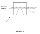
- FIG. figure 8 shows two excitation responses S'1 (T1) and S'1 (T2) as a function of time. These two excitations are respectively obtained at the first temperature T1 and at a second temperature T2 higher than T1. In both cases, the mark is not under the detector being analyzed.
- the mark is not under the analyzed proximity sensor, for example L0; this information is obtained by the fact that the previous excitation showed that the mark was under the detector L1 (obtaining a level X equal to 0); therefore, during the next excitation, it is certain that the mark is not yet under the detector L0 (the switching time of the switch 120 being chosen much greater than the time taken by the mark to switch from the detector L1 to the detector L0).
- the coil L0 is calibrated because it is certain that L0 is not under the mark for a period of time depending on the speed of rotation of the target and the shape thereof. .
- the second switch 119 has two positions 119a and 119b.
- the normal operating position (excluding reset) is the position 119a for which the negative input of the comparator 102 is connected to Vseuil_detect provided by the generator 122.
- the switch 119 is switched to its second position 119b so that the means 123 allow to inject a variable voltage Vvar on the negative input of the comparator 102 and thus to decrease the voltage Vseuil_detect initially on the input negative to a voltage Vmax for which the amplitude of the signal S'1 (T2) goes back above the voltage Vmax.
- This voltage Vmax is determined by the voltage search device 105 informed by the passage of X from 0 to 1.
- Vvar is decremented until a logic 1 is obtained.
- the computing device 106 transmits this new Vseuil_detect value to the generator 122 which will use this new value during the following detections.
- the device 100 will not detect the presence of the mark when it is not under the detector to be analyzed.
- window F_Nseuil_detect also corresponds to the feeding time of the means 123. Such a power supply reduces consumption.
- the reset is done by successive approximation by varying the value of a parameter and interpreting the binary information of the logic level X.
- Vmax is sought according to the method described above and this value is compared with respect to the preceding voltage Vmax. If the new value of Vmax is greater than the previous Vmax, then this new value of Vmax must be taken into account. Indeed, if the amplitude of the detectors has increased, even if the detector is opposite the mark, we can take into account the new value of Vmax if it is greater than the value previous, which will allow the system to not lose a turn when the brand will start turning again in the presence of a flow of fluid.
- calculation means have been described as software means programmed on a microprocessor but they can also be made using hardware means.
Abstract
Description
L'invention concerne un dispositif de détection de rotation d'un élément tournant tel que la turbine d'un compteur d'eau.The invention relates to a device for detecting rotation of a rotating element such as the turbine of a water meter.
La plupart des compteurs d'eau comprennent un totalisateur à entraînement mécanique, c'est à dire que la rotation de la turbine entraîne, par l'intermédiaire d'une transmission mécanique et/ou magnétique, les rouleaux de l'index du compteur.Most water meters include a mechanical drive totalizer, ie the rotation of the turbine drives, through a mechanical and / or magnetic transmission, the rollers of the counter index.
Il est également connu de détecter la rotation de la turbine à l'aide d'un détecteur de proximité placé en regard d'un élément tournant solidaire de la turbine et destiné à détecter le passage d'une marque placée de manière excentrée sur l'élément tournant. Le détecteur de proximité peut par exemple être basé sur une méthode inductive, auquel cas la marque sera constituée par un matériau dont les caractéristiques magnétiques et/ou électriques différent du reste de l'élément tournant. La
Le document
Un tel système de détection pose cependant certaines difficultés ; en effet, il existe une série de paramètres qui varie en fonction du temps. Par exemple, pour un compteur d'eau intégré dans un calorimètre, il s'agit de la température de l'eau qui peut faire varier les caractéristiques du détecteur, de la tension d'alimentation du circuit de détection, notamment lorsque l'alimentation se fait par l'intermédiaire d'une pile, et de la distance variable entre le détecteur de proximité et l'élément tournant due au soulèvement de la turbine à grande vitesse. Il existe également une série de paramètres qui varient d'un détecteur à l'autre et qui sont difficiles et coûteux à maîtriser dans une production en grande série; par exemple, pour un détecteur du type inductif, il s'agit notamment des valeurs de la bobine et de son coefficient de qualité, ce qui conduit à un étalonnage de chaque détecteur ou à un tri.Such a detection system, however, poses certain difficulties; indeed, there is a series of parameters that varies with time. For example, for a water meter integrated in a calorimeter, it is the water temperature that can vary the characteristics of the detector, the supply voltage of the detection circuit, especially when the power supply is via a battery, and the variable distance between the proximity sensor and the rotating element due to the high speed turbine lift. There is also a series of parameters which vary from detector to detector and which are difficult and expensive to control in mass production; for example, for a detector of the inductive type, these are in particular the values of the coil and its quality coefficient, which leads to a calibration of each detector or a sorting.
Une solution connue aux problèmes mentionnés ci-dessus est décrite dans le document
La mise en oeuvre d'une telle solution pose cependant certaines difficultés.The implementation of such a solution, however, poses certain difficulties.
En effet, le dispositif de cette solution utilise un circuit électronique complexe entraînant dès lors non seulement un temps de traitement relativement long mais également une consommation énergétique élevée.Indeed, the device of this solution uses a complex electronic circuit therefore entailing not only a relatively long processing time but also a high energy consumption.
La présente invention a pour objet un dispositif pour détecter la rotation d'un élément tournant autour d'un axe XX' selon la revendication 1.The present invention relates to a device for detecting the rotation of a member rotating about an axis XX 'according to claim 1.
Grâce à l'invention, la réinitialisation des paramètres servant à identifier le passage d'une marque au niveau des détecteurs est basé sur une recherche de ces paramètres par approximations successives à partir d'une information binaire de détection, c'est à dire une valeur de comparaison par rapport à une valeur seuil. Le dispositif de l'invention fournit un système simplifié basé sur l'interprétation d'une information binaire et non sur la mesure directe des paramètres. Cette technique de logique binaire par approximations successives permet un gain de temps et est davantage adaptée à un environnement à faible consommation, les circuits logiques utilisés étant relativement simples et peu consommateurs d'énergie.Thanks to the invention, the reinitialization of the parameters used to identify the passage of a mark at the level of the detectors is based on a search for these parameters by successive approximations from a binary detection information, ie a comparison value with respect to a threshold value. The device of the invention provides a simplified system based on the interpretation of a binary information and not on the direct measurement of the parameters. This technique of binary logic by successive approximations saves time and is more suitable for a low power environment, the logic circuits used being relatively simple and low energy consumption.
Avantageusement, ledit élément tournant est en matière non métallique et ladite marque est formée par une partie métallisée dudit élément tournant.Advantageously, said rotating element is made of non-metallic material and said mark is formed by a metallized part of said rotating element.
Avantageusement, chaque détecteur de proximité est un circuit oscillant et ledit circuit d'excitation comprend un générateur d'impulsion alimentant successivement chaque détecteur de sorte que la réponse d'excitation de chacun des détecteurs est un signal oscillant plus ou moins amorti selon que la marque est ou non au ni veau dudit détecteur, ledit signal présentant une succession de lobes positifs et négatifs d'amplitude décroissante, chaque lobe pouvant successivement être numéroté.Advantageously, each proximity detector is an oscillating circuit and said excitation circuit comprises a pulse generator successively supplying each detector so that the excitation response of each of the detectors is an oscillating signal that is more or less damped according to the mark. is at the level of said detector, said signal having a succession of positive and negative lobes of decreasing amplitude, each lobe being successively numbered.
De manière avantageuse, la durée de ladite fenêtre d'observation correspond sensiblement à la durée d'un lobe déterminé de ladite réponse d'excitation.Advantageously, the duration of said observation window substantially corresponds to the duration of a determined lobe of said excitation response.
Avantageusement, la fréquence dudit générateur d'impulsion se situe entre 50 et 500 Hz et la réponse d'excitation de chacun des détecteurs a une fréquence environ égale à 250 kHz.Advantageously, the frequency of said pulse generator is between 50 and 500 Hz and the excitation response of each of the detectors has a frequency of approximately 250 kHz.
Selon un premier mode de réalisation particulièrement avantageux, lesdits moyens de comparaison sont adaptés pour recevoir une valeur seuil de comparaison variable de sorte que l'amplitude de la réponse d'excitation de chacun des détecteurs peut être comparée avec ladite valeur seuil de comparaison variable, lesdits moyens de réinitialisation comportant :
- des moyens de détermination par itérations successives, sur une fenêtre d'observation prédéterminée, de l'amplitude de la réponse d'excitation d'un détecteur lorsque ladite marque ne peut pas être au niveau dudit détecteur, en utilisant le passage d'un état logique à l'autre dudit niveau logique issu de la comparaison de ladite amplitude de la réponse d'excitation avec ladite valeur seuil de comparaison variable,
- des moyens pour fixer ladite valeur seuil de comparaison à une valeur dépendant de ladite amplitude de la réponse d'excitation déterminée par lesdits moyens de détermination.
- means for determining, by successive iterations, on a predetermined observation window, the amplitude of the excitation response of a detector when said mark can not be at said detector, using the passage of a state logic to the other of said logic level resulting from the comparison of said amplitude of the excitation response with said variable comparison threshold value,
- means for setting said comparison threshold value to a value dependent on said amplitude of the excitation response determined by said determining means.
Avantageusement, ladite fenêtre d'observation peut varier selon le lobe choisi de sorte que lesdits moyens de comparaison sont adaptés pour effectuer une comparaison sur une fenêtre d'observation qui se décale temporellement en fonction du numéro de lobe choisi.Advantageously, said observation window may vary according to the chosen lobe so that said comparison means are adapted to perform a comparison on an observation window which is shifted temporally according to the chosen lobe number.
Selon un deuxième mode de réalisation particulièrement avantageux, lesdits moye ns de réinitialisation comporte:
- des moyens de détermination par itérations successives, pour une valeur seuil de comparaison fixée, du numéro de lobe de la réponse d'excitation d'un détecteur lorsque ladite marque ne peut pas être au niveau dudit détecteur, en utilisant le passage d'un état logique à l'autre dudit niveau logique issu de la comparaison de ladite amplitude de la réponse d'excitation avec ladite valeur seuil de comparaison fixée lorsque le numéro de lobe varie,
- des moyens pour calibrer ladite fenêtre d'observation à une valeur dépendant dudit numéro de lobe déterminé par lesdits moyens de détermination.
- successive iterative determination means, for a fixed comparison threshold value, of the lobe number of the excitation response of a detector when said mark can not be at said detector, using the passage of a state logic to the other of said logic level resulting from the comparison of said amplitude of the excitation response with said set comparison threshold value when the lobe number varies,
- means for calibrating said observation window to a value dependent on said lobe number determined by said determining means.
Avantageusement, ledit élément tournant comprend un disque solidaire de la turbine d'un compteur d'eau, ledit compteur d'eau pouvant être intégré dans un calorimètre destiné à comptabiliser l'énergie délivrée par un circuit d'eau chaude.Advantageously, said rotating element comprises a disc integral with the turbine of a water meter, said water meter being able to be integrated in a calorimeter intended to account for the energy delivered by a hot water circuit.
Avantageusement, ladite valeur seuil de comparaison est une valeur de tension.Advantageously, said comparison threshold value is a voltage value.
Avantageusement, le dispositif selon l'invention comporte :
- au moins trois détecteurs de proximité,
- des moyens pour déterminer le sens de rotation dudit élément tournant.
- at least three proximity sensors,
- means for determining the direction of rotation of said rotating member.
Avantageusement, lesdits moyens de réinitialisation fonctionnent en l'absence de rotation dudit élément tournant.Advantageously, said reset means operate in the absence of rotation of said rotating element.
D'autres caractéristiques et avantages de la présente invention apparaîtront dans la description suivante de deux modes de réalisation de l'invention donnés à titre illustratif et nullement limitatif.Other features and advantages of the present invention will appear in the following description of two embodiments of the invention given for illustrative and not limiting.
Dans les figures suivantes :
- La
figure 1 représente un système de détection selon l'état de la technique, - La
figure 2 représente un dispositif de détection selon un premier mode de réalisation de l'invention, - Les
figures 3 à 5 représentent des signaux obtenus avec un détecteur de proximité utilisé dans le dispositif de détection de lafigure 2 , - La
figure 6 représente un dispositif de détection selon un deuxième mode de réalisation de l'invention, - Les
figures 7 à 9 représentent des signaux obtenus avec un détecteur de proximité utilisé dans le dispositif de détection de lafigure 6 , - Les
figures 10 et 11 représentent trois détecteurs utilisés dans un des dispositifs représentés sur l'une desfigures 2 ou6 .
- The
figure 1 represents a detection system according to the state of the art, - The
figure 2 represents a detection device according to a first embodiment of the invention, - The
Figures 3 to 5 represent signals obtained with a proximity detector used in the detection device of thefigure 2 , - The
figure 6 represents a detection device according to a second embodiment of the invention, - The
Figures 7 to 9 represent signals obtained with a proximity detector used in the detection device of thefigure 6 , - The
Figures 10 and 11 represent three detectors used in one of the devices shown on one of thefigures 2 or6 .
La
La
Le dispositif 10 comporte :
- deux détecteurs de proximité L1 et L0 semblables aux détecteurs de la
figure 1 , un circuit d'excitation 11,- un premier commutateur 20,
un comparateur 12,- des moyens 14 pour identifier le passage de la marque au niveau des détecteurs L1 ou L0,
- des moyens de réinitialisation 13.
- two proximity sensors L1 and L0 similar to the detectors of the
figure 1 , - an
excitation circuit 11, - a
first switch 20, - a
comparator 12, - means 14 for identifying the passage of the mark at the level of the detectors L1 or L0,
- reset means 13.
Le circuit d'excitation 11 permet d'exciter les deux détecteurs L0 et L1 en même temps et de fournir en sortie une tension Vc correspondant à la réponse d'excitation de l'un des détecteurs L0 ou L1.The
Le commutateur 20 permet de fournir sur l'entrée positive du comparateur 12 la réponse d'excitation de l'un des deux détecteurs L0 ou L1.The
En fonctionnement normal, cette tension Vc est comparée avec une tension de référence Vseuil_détect fournie par un générateur 22. Cette tension de référence Vseuil_détect fixée est injectée sur l'entrée négative du comparateur 12. La
La réponse S1 (T1) est un signal faiblement amorti indiquant que la marque n'est pas sous le détecteur analysé.The response S1 (T1) is a weakly damped signal indicating that the mark is not under the detector being analyzed.
Notons que ce signal S1 (T1) (tout comme le signal S2(T1)) est un signal oscillant comportant donc une pluralité de lobes positifs et négatifs ; par la suite, nous numéroterons les lobes positifs de un en un.Note that this signal S1 (T1) (just like the signal S2 (T1)) is an oscillating signal comprising a plurality of positive and negative lobes; subsequently, we will number the positive lobes from one to one.
La comparaison de S1 (T1) avec Vseuil_détect est réalisée sur le lobe numéroté Nseuil_détect qui définit une fenêtre d'observation F _Nseuil_détect correspondant à la durée du lobe Nseuil_détect. Dans le cas de la
Sur cette fenêtre F_Nseuil_détect, l'amplitude du signal S1 (T1 ) reste supérieure à Vseuil_détect. Dès lors, le comparateur 12 donne sur sa sortie un niveau logique X égal à 1 indiquant que la marque n'est pas sous le détecteur analysée.In this window F_Nseuil_detect, the amplitude of the signal S1 (T1) remains greater than Vseuil_detect. Therefore, the
Sur cette même fenêtre, l'amplitude du signal S2(T1) passe sous la tension Vseuil_détect. Dès lors, le comparateur 12 donne sur sa sortie un niveau logique X égal à 0 indiquant que la marque est sous le détecteur analysée. Ainsi, les moyens 14 pour identifier le passage de la marque au niveau des détecteurs vont mémoriser cet état 0 dans un dispositif de mémorisation 17 et comptabiliser un demi-tour dans un dispositif de comptage 18. (1/m tour dans le cas de m détecteurs avec m supérieur ou égal à deux).In this same window, the amplitude of the signal S2 (T1) goes below the voltage Vseuil_detect. Therefore, the
Il faut toutefois noter que la température peut évoluer ; ainsi, même en l'absence de la marque au niveau d'un des détecteurs, on peut avoir la configuration illustrée en
On remarque que le signal S1(T2) se trouve systématiquement en dessous du signal S1(T1) ; en effectuant une comparaison sur la fenêtre d'observation F_Nseuil_détect précédemment définie, l'amplitude du signal S1(T2) est déjà sous le seuil Vseuil_détect alors que l'on sait que la marque n'est pas sous le détecteur. Dès lors, il est important de pouvoir réinitialiser F_Nseuil_détect de façon à obtenir un résultat cohérent. Pour cela, le deuxième commutateur 19 est commuté sur sa deuxième position 191.Note that the signal S1 (T2) is always below the signal S1 (T1); by making a comparison on the observation window F_Nseuil_etect previously defined, the amplitude of the signal S1 (T2) is already below the threshold Vseuil_detect while it is known that the mark is not under the detector. Therefore, it is important to be able to reset F_Nseuil_detect so as to obtain a coherent result. For this, the
Les moyens de réinitialisation 13 comportent :
- le deuxième commutateur 19 déjà défini,
- des moyens de commande 23 permettant d'injecter une fenêtre d'observation variable sur le comparateur 12,
- un dispositif de recherche de fenêtre d'observation 15,
- un dispositif de calcul de
F_Nseuil_détect 16.
- the
second switch 19 already defined, - control means 23 for injecting a variable observation window on the
comparator 12, - an observation
window search device 15, - a
F_Nseuil_detect calculation device 16.
Le principe de fonctionnement de ces moyens de réinitialisation 13 sera mieux compris au regard de la
Rappelons que, dans cette configuration, nous savons que la marque ne se trouve pas sous le détecteur de proximité analysé, par exemple L0 ; cette information est obtenue par le fait que l'excitation précédente a montré que la marque se trouvait sous le détecteur L1 (obtention d'un niveau X égal à 0) ; dès lors, lors de l'excitation suivante, on est sûr que la marque ne se trouve pas encore sous le détecteur L0 (le temps de commutation du commutateur 20 étant choisi largement supérieure au temps que met la marque pour passer du détecteur L1 au détecteur L0).Recall that, in this configuration, we know that the mark is not under the analyzed proximity sensor, for example L0; this information is obtained by the fact that the previous excitation showed that the mark was under the detector L1 (obtaining a level X equal to 0); therefore, during the next excitation, it is certain that the mark is not yet under the detector L0 (the switching time of the
Le deuxième commutateur 19 étant commuté sur sa deuxième position 191, les moyens de commande 23 permettent de décaler la fenêtre d'observation vers la gauche suivant la flèche en pointillés (en décrémentant de un en un le numéro de lobe) jusqu'à obtenir une fenêtre F_Nmax (correspondant au lobe placé à la position Nmax) pour laquelle l'amplitude du signal S1(T2) repasse au-dessus de la tension Vseuil_détect. Cette fenêtre F_Nmax est déterminée par dispositif de recherche de fenêtre d'observation 15 informé par le passage de X de 0 à 1.The
Une fois la fenêtre F_Nmax, et donc le numéro de lobe Nmax correspondant, déterminés, le dispositif de calcul de 16 utilise ces valeurs pour calculer un numéro de lobe Nseuil_détect réinitialisé et défini par la relation :
- Nseuil_détect = Nmax - Ns, où Ns est un entier fixe connu et propre à chaque détecteur de proximité. Il est également possible de prendre une valeur de Ns commune à chacun des détecteurs.
- Nseuil_detect = Nmax - Ns, where Ns is a fixed integer known and specific to each proximity detector. It is also possible to take a value of Ns common to each of the detectors.
Cette nouvelle valeur de Nseuil_détect définit une nouvelle fenêtre d'observation F_Nseuil_détect pour laquelle on est certain que le dispositif 10 ne détectera pas la présence de la marque lorsque celle ci n'est pas sous le détecteur à analyser.This new value of Nseuil_detect defines a new observation window F_Nseuil_détect for which it is certain that the
Ainsi, le dispositif de calcul de 16 transmet cette nouvelle valeur de F_Nseuil_détect aux moyens de commande 21 qui utiliseront cette nouvelle valeur lors des détections suivantes.Thus, the
Le principe de réinitialisation sera le même si l'amplitude du signal du détecteur analysé augmente (cas d'une diminution de température) ; dans ce cas, il faudra rechercher le nouveau lobe positif maximum pour que l'amplitude du signal soit au-dessus de la tension de comparaison Vseuil_détect fixe.The reset principle will be the same if the amplitude of the signal of the analyzed detector increases (case of a decrease of temperature); in this case, it will be necessary to search for the new maximum positive lobe so that the amplitude of the signal is above the comparison voltage Vseuil_détect fixed.
Notons que l'ensemble des moyens compris dans les moyens de réinitialisation 13 peuvent par exemple être réalisés à l'aide de moyens logiciels via la programmation d'un microprocesseur.Note that all the means included in the reset means 13 may for example be made using software means via the programming of a microprocessor.
Notons d'autre part, que, grâce à l'invention, on utilise avantageusement la valeur du niveau logique X pour à la fois comptabiliser le nombre de tours et réinitialiser le dispositif en cas de variation de certains paramètres telles que la température. La réinitialisation est ici réalisée en faisant varier la fenêtre d'observation et en gardant une tension de comparaison Vseuil_détect fixe. Nous allons voir dans la description d'un deuxième mode de réalisation qu'il est possible d'obtenir une réinitialisation en faisant varier la tension de comparaison Vseuil_détect et en gardant une fenêtre d'observation fixe.Note also that, thanks to the invention, is advantageously used the value of the logic level X to both count the number of revolutions and reset the device in case of variation of certain parameters such as temperature. The reset is performed here by varying the observation window and keeping a comparison voltage Vseuil_détect fixed. We will see in the description of a second embodiment that it is possible to obtain a reset by varying the comparison voltage Vseuil_detect and keeping a fixed observation window.
La calibration des détecteurs peut-être faite soit à chaque 1/m de tour dans le cas de m détecteurs, c'est-à-dire à chaque détection de la marque mais elle peut également être effectuée à un temps plus relaxé en fonction de la variation des paramètres d'influences, ces derniers pouvant varier relativement lentement.The calibration of the detectors can be done either every 1 / m of a turn in the case of m detectors, that is to say at each detection of the mark but it can also be performed at a more relaxed time depending on the variation of the influence parameters, the latter being able to vary relatively slowly.
La
Le dispositif 100 comporte :
- deux détecteurs de proximité L1 et L0 semblables aux détecteurs de la
figure 1 , un circuit d'excitation 101,- un premier commutateur 120,
un comparateur 102,- des moyens 104 pour identifier le passage de la marque au niveau des détecteurs L1 ou L0,
- des moyens de réinitialisation 103.
- two proximity sensors L1 and L0 similar to the detectors of the
figure 1 , - an
excitation circuit 101, - a
first switch 120, - a
comparator 102, - means 104 for identifying the passage of the mark at the level of the detectors L1 or L0,
- reset means 103.
Le circuit d'excitation 101 permet d'exciter les deux détecteurs L0 et L1 en même temps et de fournir en sortie une tension Vc correspondant à la réponse d'excitation de l'un des détecteurs L0 ou L1.The
Le commutateur 120 permet de fournir sur l'entrée positive du comparateur 102 la réponse d'excitation de l'un des deux détecteurs L0 ou L1.The
En fonctionnement normal, cette tension Vc est comparée avec une tension de référence Vseuil_détect fournie par un générateur 122. Cette tension de référence Vseuil_détect est injectée sur l'entrée négative du comparateur 102. La
La réponse S'1 (T1) est un signal faiblement amorti indiquant que la marque n'est pas sous le détecteur analysé.The response S'1 (T1) is a weakly damped signal indicating that the mark is not under the detector analyzed.
Notons que ce signal S'1 (T1) (tout comme le signal S'2(T1)) est un signal oscillant comportant donc une pluralité de lobes positifs et négatifs ; par la suite, nous numéroterons les lobes positifs de un en un.Note that this signal S'1 (T1) (just like the signal S'2 (T1)) is an oscillating signal comprising a plurality of positive and negative lobes; subsequently, we will number the positive lobes from one to one.
La comparaison de S'1 (T1 ) avec Vseuil_détect est réalisée sur le lobe numéroté Nseuil_détect qui définit une fenêtre d'observation F_Nseuil_détect correspondant à la durée du lobe Nseuil_détect. Dans le cas de la
Sur cette fenêtre F_Nseuil_détect, l'amplitude du signal S'1 (T1) reste supérieure à Vseuil_détect. Dès lors, le comparateur 102 donne sur sa sortie un niveau logique X égal à 1 indiquant que la marque n'est pas sous le détecteur analysée.On this window F_Nseuil_detect, the amplitude of the signal S'1 (T1) remains higher than Vseuil_detect. Therefore, the
Sur cette même fenêtre, l'amplitude du signal S'2(T1) passe sous la tension Vseuil_détect. Dès lors, le comparateur 102 donne sur sa sortie un niveau logique X égal à 0 indiquant que la marque est sous le détecteur analysée. Ainsi, les moyens 104 pour identifier le passage de la marque au niveau des détecteurs vont mémoriser cet état 0 dans un dispositif de mémorisation 107 et comptabiliser un demi-tour dans un dispositif de comptage 108. (1 /m tour dans le cas de m détecteurs avec m supérieur ou égal à deux).In this same window, the amplitude of the signal S'2 (T1) goes below the voltage Vseuil_detect. Therefore, the
Il faut toutefois noter que la température peut évoluer ; ainsi, même en l'absence de la marque au niveau d'un des détecteurs, on peut avoir la configuration illustrée en
On remarque que le signal S'1(T2) se trouve systématiquement en dessous du signal S'1(T1) ; en effectuant une comparaison sur la fenêtre d'observation F_Nseuil_détect précédemment définie, l'amplitude du signal S'1 (T2) est déjà sous le seuil Vseuil_détect alors que l'on sait que la marque n'est pas sous le détecteur. Dès lors, il est important de pouvoir réinitialiser Vseuil_détect de façon à obtenir un résultat cohérent. Pour cela, on utilise les moyens de réinitialisation 103 qui comportent :
un deuxième commutateur 119,- des moyens 123 permettant d'injecter une tension variable Vvar sur l'entrée négative du comparateur 102,
- un dispositif de recherche de
tension 105, - un dispositif de calcul de
Vseuil_détect 106.
- a
second switch 119, - means 123 for injecting a variable voltage Vvar on the negative input of the
comparator 102, - a
voltage search device 105, - a device for calculating
Vseuil_detect 106.
Le principe de fonctionnement de ces moyens de réinitialisation 103 sera mieux compris au regard de la
Rappelons que, dans cette configuration, nous savons que la marque ne se trouve pas sous le détecteur de proximité analysé, par exemple L0 ; cette information est obtenue par le fait que l'excitation précédente a montré que la marque se trouvait sous le détecteur L1 (obtention d'un niveau X égal à 0) ; dès lors, lors de l'excitation suivante, on est sûr que la marque ne se trouve pas encore sous le détecteur L0 (le temps de commutation du commutateur 120 étant choisi largement supérieure au temps que met la marque pour passer du détecteur L1 au détecteur L0). Ainsi, dès que la bobine L1 est détectée, on calibre la bobine L0 car on est sûr que L0 n'est pas sous la marque pendant un laps de temps dépendant de la vitesse de rotation de la cible et de la forme de celle-ci.Recall that, in this configuration, we know that the mark is not under the analyzed proximity sensor, for example L0; this information is obtained by the fact that the previous excitation showed that the mark was under the detector L1 (obtaining a level X equal to 0); therefore, during the next excitation, it is certain that the mark is not yet under the detector L0 (the switching time of the
Le deuxième commutateur 119 comporte deux positions 119a et 119b. La position de fonctionnement normal (hors réinitialisation) est la position 119a pour laquelle l'entrée négative du comparateur 102 est reliée à Vseuil_détect fournie par le générateur 122.The
Lors de la réinitialisation, le commutateur 119 est commutée sur sa deuxième position 119b de sorte que les moyens 123 permettent d'injecter une tension variable Vvar sur l'entrée négative du comparateur 102 et donc de faire décroître la tension Vseuil_détect initialement sur l'entrée négative jusqu'à une tension Vmax pour laquelle l'amplitude du signal S'1(T2) repasse au-dessus de la tension Vmax. Cette tension Vmax est déterminée par le dispositif de recherche de tension 105 informé par le passage de X de 0 à 1. Ainsi, on décrémente Vvar jusqu'obtenir un 1 logique.During the reset, the
Une fois la tension Vmax déterminée, le dispositif de calcul de Vseuil_détect 106 utilise cette valeur pour calculer une tension Vseuil_détect réinitialisée et défini par la relation :
- Vseuil_détect = Vmax - ΔV, où ΔV est une valeur connue et propre à chaque détecteur de proximité. Il est également possible de prendre une valeur de ΔV commune à chacun des détecteurs.
- Vseuil_detect = Vmax - ΔV, where ΔV is a known value specific to each proximity detector. It is also possible to take a value of ΔV common to each of the detectors.
Ainsi, le dispositif de calcul de 106 transmet cette nouvelle valeur de Vseuil_détect au générateur 122 qui utilisera cette nouvelle valeur lors des détections suivantes.Thus, the
On est certain que, pour cette nouvelle valeur de Vseuil_détect, le dispositif 100 ne détectera pas la présence de la marque lorsque celle ci n'est pas sous le détecteur à analyser.It is certain that for this new value of Vseuil_detect, the
Le principe est le même, si l'amplitude du signal du détecteur augmente (diminution de la température), c'est-à-dire qu'il faut augmenter le signal jusqu'à ce que le dispositif donne l'information binaire X=0.The principle is the same, if the amplitude of the signal of the detector increases (decrease of the temperature), that is to say that it is necessary to increase the signal until the device gives the binary information X = 0.
Notons que la fenêtre F_Nseuil_détect correspond également à la durée d'alimentation des moyens 123. Une telle alimentation permet de réduire la consommation.Note that the window F_Nseuil_detect also corresponds to the feeding time of the
Dans les deux modes de réalisation décrits aux
La réinitialisation exposée ci-dessus n'a été envisagée que lorsque la marque est en mouvement ; toutefois, il est également possible d'effectuer cette réinitialisation lorsque la marque est immobile. Pour cela, on recherche la tension Vmax suivant le procédé décrit plus haut et on compare cette valeur par rapport à la tension Vmax précédente. Si la nouvelle valeur de Vmax est supérieure au Vmax précédent, il faut alors prendre en compte cette nouvelle valeur de Vmax. En effet, si l'amplitude des détecteurs a augmenté, même si le détecteur est en regard de la marque, on peut prendre en compte la nouvelle valeur de Vmax si elle est supérieure à la valeur précédente, ce qui permettra au système de ne pas perdre de tour quand la marque recommencera à tourner en présence d'un débit de fluide.The reset discussed above was only considered when the mark is in motion; however, it is also possible to perform this reset when the mark is stationary. For this, the voltage Vmax is sought according to the method described above and this value is compared with respect to the preceding voltage Vmax. If the new value of Vmax is greater than the previous Vmax, then this new value of Vmax must be taken into account. Indeed, if the amplitude of the detectors has increased, even if the detector is opposite the mark, we can take into account the new value of Vmax if it is greater than the value previous, which will allow the system to not lose a turn when the brand will start turning again in the presence of a flow of fluid.
Bien entendu, la présente invention n'est pas limitée aux modes de réalisations qui viennent d'être décrits.Of course, the present invention is not limited to the embodiments that have just been described.
Notamment, nous avons décrit l'invention dans le cas de deux détecteurs de proximité ; il est clair que l'invention s'applique également en présence d'un nombre m plus élevé de détecteurs. Au moins trois détecteurs L0, L1 et L2 peuvent ainsi s'avérer nécessaire pour détecter le sens de rotation du disque. Les
- a) Après que L0 ( c'est à dire Ln avec n=0) ait été détecté (c'est à dire que la marque se trouve sous L0), si le détecteur suivant détecté est L1 (c'est-à-dire Ln+1) alors la marque tourne dans le sens de rotation positif (
figure 10 ). - b) Après que L2 ait été détecté, si le détecteur suivant détecté est L1, alors la marque tourne dans le sens de rotation négatif (
figure 11 ).
- a) After L0 (ie Ln with n = 0) has been detected (ie the mark is under L0), if the next detector detected is L1 (ie Ln + 1) then the mark rotates in the direction of positive rotation (
figure 10 ). - b) After L2 has been detected, if the next detector detected is L1, then the mark rotates in the negative direction of rotation (
figure 11 ).
De même, les moyens de calculs ont été décrits comme des moyens logiciels programmés sur un microprocesseur mais ils peuvent également être réalisés à l'aide de moyens matériels.Similarly, the calculation means have been described as software means programmed on a microprocessor but they can also be made using hardware means.
Notons également que nous avons considéré la température comme paramètre faisant varier les caractéristiques des détecteurs. Toutefois, d'autres paramètres (humidité, vieillissement, tension d'alimentation,...) peuvent également être pris en compte. La calibration permet ainsi de suivre les variations du coefficient de qualité des détecteurs.It should also be noted that we have considered temperature as a parameter that varies the characteristics of the detectors. However, other parameters (humidity, aging, supply voltage, ...) can also be taken into account. The calibration thus makes it possible to follow the variations of the quality coefficient of the detectors.
Claims (13)
- A device (10, 100) for detecting the rotation of a rotary element around an axis XX', comprising:- m proximity detectors (L0, L1) situated in a plane perpendicular to the axis XX' in m radial directions, m being an integer greater than or equal to 2, a mark being secured to said rotary element and eccentric relative to the axis XX' and being able to modify the amplitude response of said proximity detectors when said rotary element is rotated,- an excitation circuit (11, 101) intended to excite said proximity detectors, each of said detectors supplying an excitation response when it is excited,said device (10, 100) being characterized in that it comprises:- means (12, 102) for comparing the amplitude of the excitation response of each of the detectors (L0, L1) with a threshold comparison value, during a time period, called observation window, and to supply a logic level 1 or 0 depending on whether the response amplitude is above or below said comparison threshold vale,- means (14, 104) for identifying the passage of said mark at one of said detectors (L0, L1) as a function of the value 0 or 1 of said logic level,- reinitialization means (13, 103) to vary either said comparison threshold value, or said observation window, characteristic of a detector (L0, L1) inasmuch as the comparison means (12, 102) supply a logic level representative of the passage of said mark at said detector whereas said mark cannot be at the level of said detector (L0, L1), said reinitialization consisting of looking, through successive iterations, either for a new comparison threshold value, or a new observation window, for which the comparison means (12, 102) supply a logic level representative of the absence of passage of said mark at said detector.
- The device (10, 100) according to claim 1, characterized in that said rotary element is made from a nonmetallic material and said mark is formed by a metallized part of said rotary element.
- The device (10, 100) according to claim 1 or 2, characterized in that each proximity detector is an oscillating circuit and said excitation circuit comprises a pulse generator successively powering each detector so that the excitation response of each of the detectors is an oscillating signal that is more or less damped depending on whether the mark is at said detector, said signal having a series of positive and negative lobes of decreasing amplitude, each lobe successively being able to be numbered.
- The device (10, 100) according to claim 3, characterized in that the duration of the said observation window substantially corresponds to the duration of a particular lobe of said excitation response.
- The device (10, 100) according to one of claims 3 or 4, characterized in that the frequency of said pulse generator is situated between 50 and 500 Hz.
- The device (10, 100) according to one of claims 3 to 5, characterized in that the excitation response of each of the detectors has a frequency approximately equal to 250 kHz.
- The device (100) according to one of claims 1 to 6, characterized in that said comparison means (102) are adapted to receive a variable comparison threshold value (Vvar) so that the amplitude of the excitation response of each of the detectors (L0, L1) can be compared with said variable comparison threshold value (Vvar), said reinitialization means (103) comprising:- means (105) for determination, through successive iterations, over a predetermined observation window, the amplitude of the excitation response of a detector when said mark cannot be at the level of said detector, using the transition from one logic state to the other logic level resulting from the comparison of said amplitude of the excitation response with said variable comparison threshold value,- means (106) for calibrating said comparison threshold value to a value depending on said amplitude of the excitation response determined by said determination means (105).
- The device (10) according to one of claims 4 to 6, characterized in that said observation window can vary depending on the chosen lobe so that said comparison means (12) are adapted to perform a comparison on the observation window that is time-shifted as a function of the chosen lobe number.
- The device (10) according to claim 8, characterized in that said reinitialization means comprise:- means (15) for determining, through successive iterations, for a fixed comparison threshold value, the lobe number of the excitation response of a detector (L0, L1) when said mark cannot be at the level of said detector, using the transition from one logic state to the other of said logic level resulting from the comparison of said amplitude of the excitation response with said fixed comparison threshold value when the lobe number varies,- means (16) for calibrating said observation window to a value depending on said lobe number determined by said determination means (15).
- The device (10, 100) according to one of the preceding claims, characterized in that said rotary element comprises a disk secured to the turbine of a water meter, said water meter being able to be incorporated into a calorimeter intended to count the energy delivered by a hot water circuit.
- The device (10, 100) according to one of the preceding claims, characterized in that said comparison threshold value is a voltage value.
- The device according to one of the preceding claims, characterized in that it comprises:- at least three proximity detectors (L0, L1, L2),- means for determining the direction of rotation of said rotary element.
- The device according to one of the preceding claims, characterized in that said reinitialization means (13, 103) operate in the absence of rotation of said rotary element.
Applications Claiming Priority (2)
| Application Number | Priority Date | Filing Date | Title |
|---|---|---|---|
| FR0351240 | 2003-12-31 | ||
| FR0351240A FR2864615B1 (en) | 2003-12-31 | 2003-12-31 | DEVICE FOR DETECTING A ROTATING ELEMENT SUCH AS THE TURBINE OF A WATER METER |
Publications (2)
| Publication Number | Publication Date |
|---|---|
| EP1550844A1 EP1550844A1 (en) | 2005-07-06 |
| EP1550844B1 true EP1550844B1 (en) | 2012-02-29 |
Family
ID=34566401
Family Applications (1)
| Application Number | Title | Priority Date | Filing Date |
|---|---|---|---|
| EP04300958A Not-in-force EP1550844B1 (en) | 2003-12-31 | 2004-12-31 | Device for detecting the movement of a rotating element, such as the turbine in a water meter |
Country Status (6)
| Country | Link |
|---|---|
| US (1) | US7106054B2 (en) |
| EP (1) | EP1550844B1 (en) |
| CN (1) | CN1651866A (en) |
| AT (1) | ATE547691T1 (en) |
| ES (1) | ES2386009T3 (en) |
| FR (1) | FR2864615B1 (en) |
Families Citing this family (7)
| Publication number | Priority date | Publication date | Assignee | Title |
|---|---|---|---|---|
| JP4476326B2 (en) * | 2005-05-31 | 2010-06-09 | 富士通株式会社 | Data receiver |
| FR3025309B1 (en) * | 2014-08-28 | 2018-03-16 | Sagemcom Energy & Telecom Sas | DEVICE FOR COUNTING TIRES OF A WHEEL BY MEANS OF A COIL AND COUNTER EQUIPPED WITH SAID COUNTER DEVICE |
| FR3026839B1 (en) * | 2014-10-03 | 2016-11-04 | Sagemcom Energy & Telecom Sas | METHOD OF AUTO-CALIBRATING A DEVICE FOR COUNTING TURNS ON A WHEEL |
| FR3027105B1 (en) * | 2014-10-13 | 2018-02-16 | Sagemcom Energy & Telecom Sas | METHOD FOR AUTO-CALIBRATING A DEVICE FOR COUNTING TURNS OF A WHEEL BY ADJUSTING A REFERENCE VOLTAGE |
| EP3401648A1 (en) | 2017-05-09 | 2018-11-14 | Aiut Sp. z o.o. | A mechanical drum-type counter for a consumption meter |
| CN107576336B (en) * | 2017-08-29 | 2020-05-26 | 重庆智慧水务有限公司 | Non-magnetic sensor |
| FR3131957B1 (en) * | 2022-01-17 | 2024-01-05 | St Microelectronics Grenoble 2 | Excitation and reading of an LC oscillator network |
Family Cites Families (4)
| Publication number | Priority date | Publication date | Assignee | Title |
|---|---|---|---|---|
| FR2664973B1 (en) * | 1990-07-20 | 1992-10-23 | Schlumberger Ind Sa | DEVICE FOR DETECTING THE ROTATION OF A ROTATING ELEMENT SUCH AS THE TURBINE OF A WATER METER. |
| DE4137695C2 (en) * | 1991-11-15 | 1994-12-01 | Texas Instruments Deutschland | Sensor arrangement for determining the state of motion of a rotor |
| US5450760A (en) * | 1993-10-18 | 1995-09-19 | Lew; Hyok S. | Turbine flowmeter with capacitive transducer |
| US6012339A (en) * | 1997-03-31 | 2000-01-11 | Lake Monitors, Inc. | Tangential rotor flow rate meter |
-
2003
- 2003-12-31 FR FR0351240A patent/FR2864615B1/en not_active Expired - Fee Related
-
2004
- 2004-12-22 US US11/020,637 patent/US7106054B2/en not_active Expired - Fee Related
- 2004-12-31 AT AT04300958T patent/ATE547691T1/en active
- 2004-12-31 CN CN200410075871.6A patent/CN1651866A/en active Pending
- 2004-12-31 EP EP04300958A patent/EP1550844B1/en not_active Not-in-force
- 2004-12-31 ES ES04300958T patent/ES2386009T3/en active Active
Also Published As
| Publication number | Publication date |
|---|---|
| US7106054B2 (en) | 2006-09-12 |
| ES2386009T3 (en) | 2012-08-07 |
| FR2864615A1 (en) | 2005-07-01 |
| FR2864615B1 (en) | 2006-03-10 |
| US20050140364A1 (en) | 2005-06-30 |
| ATE547691T1 (en) | 2012-03-15 |
| EP1550844A1 (en) | 2005-07-06 |
| CN1651866A (en) | 2005-08-10 |
Similar Documents
| Publication | Publication Date | Title |
|---|---|---|
| EP0467753B1 (en) | Device for detecting the movement of a rotating element such as the turbine in a water meter | |
| EP2496914B1 (en) | Bidirectional magnetic position sensor having field rotation | |
| EP3037898B1 (en) | Electromechanical apparatus comprising a device for capacitive detection of the angular position of a moving element, and method for detecting the angular position of a moving element | |
| WO2017088968A1 (en) | Method of automatic calibration of a camshaft sensor for motor vehicle engine | |
| FR2978833A1 (en) | AUTOMATIC CALIBRATION METHOD OF CAMSHAFT SENSOR FOR MOTOR VEHICLE | |
| CH679347A5 (en) | ||
| EP0952426B1 (en) | Timepiece having an inductive or capacitive sensor for detecting at least one angular position of gear-wheel within the timepiece | |
| FR3029283A1 (en) | CAMSHAFT OR CRANKSHAFT SENSOR FOR MOTOR VEHICLE AND METHOD FOR DIAGNOSING SUCH SENSOR | |
| EP1550844B1 (en) | Device for detecting the movement of a rotating element, such as the turbine in a water meter | |
| FR3041426A1 (en) | AUTOMATIC CALIBRATION METHOD OF CAMSHAFT SENSOR FOR MOTOR VEHICLE ENGINE | |
| EP0734510B1 (en) | Method and device for monitoring changes in the current value of a fluid flow rate in a fluid meter | |
| CA2728491A1 (en) | Method and system for determining the angular position of a turbojet engine rotor | |
| CH678985A5 (en) | ||
| EP1756526B1 (en) | Device and method for determining the position of an engine | |
| EP1194999B1 (en) | Method for setting a polyphase electric stepper motor | |
| FR2880682A1 (en) | POSITION SENSOR WITH CYCLIC IMBALANCE | |
| EP4042113B1 (en) | Method of detection of an absolute angular position or of an absolute angular displacement stroke of a rotating organ | |
| CH679086A5 (en) | ||
| WO2019020903A1 (en) | Method and device for detecting an inverted connection of a crankshaft sensor | |
| EP0150642A2 (en) | Detection device for the rotation angle of a spinning gear | |
| FR2696233A1 (en) | Incremental sensor with failure signaling. | |
| CH710522A2 (en) | Electromechanical apparatus comprising a device for capacitively detecting the angular position of a mobile, and method for detecting the angular position of a mobile. | |
| FR3027103A1 (en) | ANGULAR POSITION SENSOR ASSEMBLY FOR HYBRID MOTOR VEHICLE WITH COMMON SHAFT | |
| FR3069635B1 (en) | AUTOMATIC CALIBRATION METHOD OF CAMSHAFT SENSOR FOR MOTOR VEHICLE ENGINE | |
| FR2593290A1 (en) | Detector for measuring speed and sense of rotation for a rotary machine |
Legal Events
| Date | Code | Title | Description |
|---|---|---|---|
| PUAI | Public reference made under article 153(3) epc to a published international application that has entered the european phase |
Free format text: ORIGINAL CODE: 0009012 |
|
| AK | Designated contracting states |
Kind code of ref document: A1 Designated state(s): AT BE BG CH CY CZ DE DK EE ES FI FR GB GR HU IE IS IT LI LT LU MC NL PL PT RO SE SI SK TR |
|
| AX | Request for extension of the european patent |
Extension state: AL BA HR LV MK YU |
|
| 17P | Request for examination filed |
Effective date: 20060109 |
|
| AKX | Designation fees paid |
Designated state(s): AT BE BG CH CY CZ DE DK EE ES FI FR GB GR HU IE IS IT LI LT LU MC NL PL PT RO SE SI SK TR |
|
| 17Q | First examination report despatched |
Effective date: 20091013 |
|
| GRAP | Despatch of communication of intention to grant a patent |
Free format text: ORIGINAL CODE: EPIDOSNIGR1 |
|
| GRAS | Grant fee paid |
Free format text: ORIGINAL CODE: EPIDOSNIGR3 |
|
| GRAA | (expected) grant |
Free format text: ORIGINAL CODE: 0009210 |
|
| AK | Designated contracting states |
Kind code of ref document: B1 Designated state(s): AT BE BG CH CY CZ DE DK EE ES FI FR GB GR HU IE IS IT LI LT LU MC NL PL PT RO SE SI SK TR |
|
| RAP1 | Party data changed (applicant data changed or rights of an application transferred) |
Owner name: ITRON FRANCE |
|
| REG | Reference to a national code |
Ref country code: GB Ref legal event code: FG4D Free format text: NOT ENGLISH Ref country code: CH Ref legal event code: EP |
|
| REG | Reference to a national code |
Ref country code: DE Ref legal event code: R081 Ref document number: 602004036691 Country of ref document: DE Owner name: ITRON GLOBAL SARL, LIBERTY LAKE, US Free format text: FORMER OWNER: ACTARIS S.A.S., BOULOGNE, FR |
|
| REG | Reference to a national code |
Ref country code: AT Ref legal event code: REF Ref document number: 547691 Country of ref document: AT Kind code of ref document: T Effective date: 20120315 |
|
| REG | Reference to a national code |
Ref country code: IE Ref legal event code: FG4D Free format text: LANGUAGE OF EP DOCUMENT: FRENCH |
|
| REG | Reference to a national code |
Ref country code: DE Ref legal event code: R096 Ref document number: 602004036691 Country of ref document: DE Effective date: 20120426 |
|
| REG | Reference to a national code |
Ref country code: NL Ref legal event code: VDEP Effective date: 20120229 |
|
| LTIE | Lt: invalidation of european patent or patent extension |
Effective date: 20120229 |
|
| PG25 | Lapsed in a contracting state [announced via postgrant information from national office to epo] |
Ref country code: LT Free format text: LAPSE BECAUSE OF FAILURE TO SUBMIT A TRANSLATION OF THE DESCRIPTION OR TO PAY THE FEE WITHIN THE PRESCRIBED TIME-LIMIT Effective date: 20120229 Ref country code: NL Free format text: LAPSE BECAUSE OF FAILURE TO SUBMIT A TRANSLATION OF THE DESCRIPTION OR TO PAY THE FEE WITHIN THE PRESCRIBED TIME-LIMIT Effective date: 20120229 Ref country code: IS Free format text: LAPSE BECAUSE OF FAILURE TO SUBMIT A TRANSLATION OF THE DESCRIPTION OR TO PAY THE FEE WITHIN THE PRESCRIBED TIME-LIMIT Effective date: 20120629 |
|
| REG | Reference to a national code |
Ref country code: ES Ref legal event code: FG2A Ref document number: 2386009 Country of ref document: ES Kind code of ref document: T3 Effective date: 20120807 |
|
| PG25 | Lapsed in a contracting state [announced via postgrant information from national office to epo] |
Ref country code: FI Free format text: LAPSE BECAUSE OF FAILURE TO SUBMIT A TRANSLATION OF THE DESCRIPTION OR TO PAY THE FEE WITHIN THE PRESCRIBED TIME-LIMIT Effective date: 20120229 Ref country code: PT Free format text: LAPSE BECAUSE OF FAILURE TO SUBMIT A TRANSLATION OF THE DESCRIPTION OR TO PAY THE FEE WITHIN THE PRESCRIBED TIME-LIMIT Effective date: 20120629 Ref country code: GR Free format text: LAPSE BECAUSE OF FAILURE TO SUBMIT A TRANSLATION OF THE DESCRIPTION OR TO PAY THE FEE WITHIN THE PRESCRIBED TIME-LIMIT Effective date: 20120530 |
|
| REG | Reference to a national code |
Ref country code: AT Ref legal event code: MK05 Ref document number: 547691 Country of ref document: AT Kind code of ref document: T Effective date: 20120229 |
|
| REG | Reference to a national code |
Ref country code: IE Ref legal event code: FD4D |
|
| PG25 | Lapsed in a contracting state [announced via postgrant information from national office to epo] |
Ref country code: CY Free format text: LAPSE BECAUSE OF FAILURE TO SUBMIT A TRANSLATION OF THE DESCRIPTION OR TO PAY THE FEE WITHIN THE PRESCRIBED TIME-LIMIT Effective date: 20120229 |
|
| PG25 | Lapsed in a contracting state [announced via postgrant information from national office to epo] |
Ref country code: SE Free format text: LAPSE BECAUSE OF FAILURE TO SUBMIT A TRANSLATION OF THE DESCRIPTION OR TO PAY THE FEE WITHIN THE PRESCRIBED TIME-LIMIT Effective date: 20120229 Ref country code: DK Free format text: LAPSE BECAUSE OF FAILURE TO SUBMIT A TRANSLATION OF THE DESCRIPTION OR TO PAY THE FEE WITHIN THE PRESCRIBED TIME-LIMIT Effective date: 20120229 Ref country code: RO Free format text: LAPSE BECAUSE OF FAILURE TO SUBMIT A TRANSLATION OF THE DESCRIPTION OR TO PAY THE FEE WITHIN THE PRESCRIBED TIME-LIMIT Effective date: 20120229 Ref country code: SI Free format text: LAPSE BECAUSE OF FAILURE TO SUBMIT A TRANSLATION OF THE DESCRIPTION OR TO PAY THE FEE WITHIN THE PRESCRIBED TIME-LIMIT Effective date: 20120229 Ref country code: PL Free format text: LAPSE BECAUSE OF FAILURE TO SUBMIT A TRANSLATION OF THE DESCRIPTION OR TO PAY THE FEE WITHIN THE PRESCRIBED TIME-LIMIT Effective date: 20120229 Ref country code: EE Free format text: LAPSE BECAUSE OF FAILURE TO SUBMIT A TRANSLATION OF THE DESCRIPTION OR TO PAY THE FEE WITHIN THE PRESCRIBED TIME-LIMIT Effective date: 20120229 Ref country code: CZ Free format text: LAPSE BECAUSE OF FAILURE TO SUBMIT A TRANSLATION OF THE DESCRIPTION OR TO PAY THE FEE WITHIN THE PRESCRIBED TIME-LIMIT Effective date: 20120229 Ref country code: IE Free format text: LAPSE BECAUSE OF FAILURE TO SUBMIT A TRANSLATION OF THE DESCRIPTION OR TO PAY THE FEE WITHIN THE PRESCRIBED TIME-LIMIT Effective date: 20120229 |
|
| PG25 | Lapsed in a contracting state [announced via postgrant information from national office to epo] |
Ref country code: SK Free format text: LAPSE BECAUSE OF FAILURE TO SUBMIT A TRANSLATION OF THE DESCRIPTION OR TO PAY THE FEE WITHIN THE PRESCRIBED TIME-LIMIT Effective date: 20120229 |
|
| PLBE | No opposition filed within time limit |
Free format text: ORIGINAL CODE: 0009261 |
|
| STAA | Information on the status of an ep patent application or granted ep patent |
Free format text: STATUS: NO OPPOSITION FILED WITHIN TIME LIMIT |
|
| PG25 | Lapsed in a contracting state [announced via postgrant information from national office to epo] |
Ref country code: AT Free format text: LAPSE BECAUSE OF FAILURE TO SUBMIT A TRANSLATION OF THE DESCRIPTION OR TO PAY THE FEE WITHIN THE PRESCRIBED TIME-LIMIT Effective date: 20120229 |
|
| 26N | No opposition filed |
Effective date: 20121130 |
|
| REG | Reference to a national code |
Ref country code: DE Ref legal event code: R097 Ref document number: 602004036691 Country of ref document: DE Effective date: 20121130 |
|
| BERE | Be: lapsed |
Owner name: ITRON FRANCE Effective date: 20121231 |
|
| PG25 | Lapsed in a contracting state [announced via postgrant information from national office to epo] |
Ref country code: BG Free format text: LAPSE BECAUSE OF FAILURE TO SUBMIT A TRANSLATION OF THE DESCRIPTION OR TO PAY THE FEE WITHIN THE PRESCRIBED TIME-LIMIT Effective date: 20120529 Ref country code: MC Free format text: LAPSE BECAUSE OF NON-PAYMENT OF DUE FEES Effective date: 20121231 |
|
| REG | Reference to a national code |
Ref country code: CH Ref legal event code: PL |
|
| GBPC | Gb: european patent ceased through non-payment of renewal fee |
Effective date: 20121231 |
|
| REG | Reference to a national code |
Ref country code: FR Ref legal event code: ST Effective date: 20130830 |
|
| PG25 | Lapsed in a contracting state [announced via postgrant information from national office to epo] |
Ref country code: BE Free format text: LAPSE BECAUSE OF NON-PAYMENT OF DUE FEES Effective date: 20121231 |
|
| REG | Reference to a national code |
Ref country code: DE Ref legal event code: R119 Ref document number: 602004036691 Country of ref document: DE Effective date: 20130702 |
|
| PG25 | Lapsed in a contracting state [announced via postgrant information from national office to epo] |
Ref country code: DE Free format text: LAPSE BECAUSE OF NON-PAYMENT OF DUE FEES Effective date: 20130702 Ref country code: CH Free format text: LAPSE BECAUSE OF NON-PAYMENT OF DUE FEES Effective date: 20121231 Ref country code: LI Free format text: LAPSE BECAUSE OF NON-PAYMENT OF DUE FEES Effective date: 20121231 |
|
| REG | Reference to a national code |
Ref country code: DE Ref legal event code: R073 Ref document number: 602004036691 Country of ref document: DE |
|
| PG25 | Lapsed in a contracting state [announced via postgrant information from national office to epo] |
Ref country code: FR Free format text: LAPSE BECAUSE OF NON-PAYMENT OF DUE FEES Effective date: 20130102 Ref country code: GB Free format text: LAPSE BECAUSE OF NON-PAYMENT OF DUE FEES Effective date: 20121231 |
|
| REG | Reference to a national code |
Ref country code: DE Ref legal event code: R074 Ref document number: 602004036691 Country of ref document: DE |
|
| PG25 | Lapsed in a contracting state [announced via postgrant information from national office to epo] |
Ref country code: IT Free format text: LAPSE BECAUSE OF NON-PAYMENT OF DUE FEES Effective date: 20121231 |
|
| REG | Reference to a national code |
Ref country code: DE Ref legal event code: R074 Ref document number: 602004036691 Country of ref document: DE Effective date: 20131202 Ref country code: DE Ref legal event code: R074 Ref document number: 602004036691 Country of ref document: DE Effective date: 20131205 |
|
| PGRI | Patent reinstated in contracting state [announced from national office to epo] |
Ref country code: DE Effective date: 20131202 |
|
| PGFP | Annual fee paid to national office [announced via postgrant information from national office to epo] |
Ref country code: IT Payment date: 20131223 Year of fee payment: 10 |
|
| PGRI | Patent reinstated in contracting state [announced from national office to epo] |
Ref country code: IT Effective date: 20140101 |
|
| REG | Reference to a national code |
Ref country code: GB Ref legal event code: S28 Free format text: APPLICATION FILED |
|
| PG25 | Lapsed in a contracting state [announced via postgrant information from national office to epo] |
Ref country code: TR Free format text: LAPSE BECAUSE OF FAILURE TO SUBMIT A TRANSLATION OF THE DESCRIPTION OR TO PAY THE FEE WITHIN THE PRESCRIBED TIME-LIMIT Effective date: 20120229 |
|
| PG25 | Lapsed in a contracting state [announced via postgrant information from national office to epo] |
Ref country code: LU Free format text: LAPSE BECAUSE OF NON-PAYMENT OF DUE FEES Effective date: 20121231 |
|
| REG | Reference to a national code |
Ref country code: GB Ref legal event code: S28 Free format text: RESTORATION ALLOWED Effective date: 20140509 |
|
| PG25 | Lapsed in a contracting state [announced via postgrant information from national office to epo] |
Ref country code: HU Free format text: LAPSE BECAUSE OF FAILURE TO SUBMIT A TRANSLATION OF THE DESCRIPTION OR TO PAY THE FEE WITHIN THE PRESCRIBED TIME-LIMIT Effective date: 20041231 |
|
| PGFP | Annual fee paid to national office [announced via postgrant information from national office to epo] |
Ref country code: GB Payment date: 20140321 Year of fee payment: 10 |
|
| GBPC | Gb: european patent ceased through non-payment of renewal fee |
Effective date: 20141231 |
|
| PG25 | Lapsed in a contracting state [announced via postgrant information from national office to epo] |
Ref country code: GB Free format text: LAPSE BECAUSE OF NON-PAYMENT OF DUE FEES Effective date: 20141231 |
|
| PG25 | Lapsed in a contracting state [announced via postgrant information from national office to epo] |
Ref country code: IT Free format text: LAPSE BECAUSE OF NON-PAYMENT OF DUE FEES Effective date: 20141231 |
|
| REG | Reference to a national code |
Ref country code: DE Ref legal event code: R081 Ref document number: 602004036691 Country of ref document: DE Owner name: ITRON GLOBAL SARL, LIBERTY LAKE, US Free format text: FORMER OWNER: ITRON FRANCE, ISSY-LES-MOULINEAUX, FR Ref country code: DE Ref legal event code: R082 Ref document number: 602004036691 Country of ref document: DE Representative=s name: GROSSE, SCHUMACHER, KNAUER, VON HIRSCHHAUSEN, DE |
|
| REG | Reference to a national code |
Ref country code: ES Ref legal event code: PC2A Owner name: ITRON GLOBAL SARL Effective date: 20170130 |
|
| PGFP | Annual fee paid to national office [announced via postgrant information from national office to epo] |
Ref country code: DE Payment date: 20211109 Year of fee payment: 18 |
|
| PGFP | Annual fee paid to national office [announced via postgrant information from national office to epo] |
Ref country code: ES Payment date: 20220104 Year of fee payment: 18 |
|
| REG | Reference to a national code |
Ref country code: DE Ref legal event code: R119 Ref document number: 602004036691 Country of ref document: DE |
|
| PG25 | Lapsed in a contracting state [announced via postgrant information from national office to epo] |
Ref country code: DE Free format text: LAPSE BECAUSE OF NON-PAYMENT OF DUE FEES Effective date: 20230701 |
|
| REG | Reference to a national code |
Ref country code: ES Ref legal event code: FD2A Effective date: 20240202 |
|
| PG25 | Lapsed in a contracting state [announced via postgrant information from national office to epo] |
Ref country code: ES Free format text: LAPSE BECAUSE OF NON-PAYMENT OF DUE FEES Effective date: 20230101 |