EP1550578A2 - Auslösevorrichtung für ein Kfz-Blinkersystem - Google Patents
Auslösevorrichtung für ein Kfz-Blinkersystem Download PDFInfo
- Publication number
- EP1550578A2 EP1550578A2 EP04106717A EP04106717A EP1550578A2 EP 1550578 A2 EP1550578 A2 EP 1550578A2 EP 04106717 A EP04106717 A EP 04106717A EP 04106717 A EP04106717 A EP 04106717A EP 1550578 A2 EP1550578 A2 EP 1550578A2
- Authority
- EP
- European Patent Office
- Prior art keywords
- ring
- elastically deformable
- portions
- deformable portion
- ring portion
- Prior art date
- Legal status (The legal status is an assumption and is not a legal conclusion. Google has not performed a legal analysis and makes no representation as to the accuracy of the status listed.)
- Withdrawn
Links
Images

Classifications
-
- B—PERFORMING OPERATIONS; TRANSPORTING
- B60—VEHICLES IN GENERAL
- B60Q—ARRANGEMENT OF SIGNALLING OR LIGHTING DEVICES, THE MOUNTING OR SUPPORTING THEREOF OR CIRCUITS THEREFOR, FOR VEHICLES IN GENERAL
- B60Q1/00—Arrangement of optical signalling or lighting devices, the mounting or supporting thereof or circuits therefor
- B60Q1/26—Arrangement of optical signalling or lighting devices, the mounting or supporting thereof or circuits therefor the devices being primarily intended to indicate the vehicle, or parts thereof, or to give signals, to other traffic
- B60Q1/34—Arrangement of optical signalling or lighting devices, the mounting or supporting thereof or circuits therefor the devices being primarily intended to indicate the vehicle, or parts thereof, or to give signals, to other traffic for indicating change of drive direction
- B60Q1/40—Arrangement of optical signalling or lighting devices, the mounting or supporting thereof or circuits therefor the devices being primarily intended to indicate the vehicle, or parts thereof, or to give signals, to other traffic for indicating change of drive direction having mechanical, electric or electronic automatic return to inoperative position
- B60Q1/42—Arrangement of optical signalling or lighting devices, the mounting or supporting thereof or circuits therefor the devices being primarily intended to indicate the vehicle, or parts thereof, or to give signals, to other traffic for indicating change of drive direction having mechanical, electric or electronic automatic return to inoperative position having mechanical automatic return to inoperative position due to steering-wheel position, e.g. with roller wheel control
Definitions
- the present invention relates to a device for trigger for a flashing system a vehicle.
- vehicles are equipped with a turn signal system, associated with the steering group of the vehicle and including a selection lever, which can manually operated by the driver, turn the lever itself from a neutral position clockwise or in the opposite direction, in order to control the ignition of direction indicators and therefore signal the intention a change of direction to the right or well, respectively, on the left.
- a turn signal system associated with the steering group of the vehicle and including a selection lever, which can manually operated by the driver, turn the lever itself from a neutral position clockwise or in the opposite direction, in order to control the ignition of direction indicators and therefore signal the intention a change of direction to the right or well, respectively, on the left.
- a triggering device coupled to said lever of selection and actuated by the rotation of the column of steering group.
- a trigger device comprising two elements to separate ring, which are articulated to a structure of support in coaxial positions, around an axis parallel to the axis of the column, which are connected between them by an elastic element with flower made of material metallic and which have respective teeth, which stand out through the support structure, so to interact with radial reliefs of the column, during the rotation of the latter around his own axis.
- the triggering device has a relatively high number of components and therefore requires relatively high costs and costs for its production.
- the object of the present invention is to realize a triggering device for a system of flashing light of a vehicle, which allows to solve, simple and economical way, the problems outlined above.
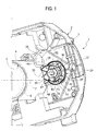
- 1 indicates a triggering device for a system of indicators of a vehicle, which is carried by a structure 2 (partially illustrated) comprising a plate 3 and a tubular portion 4, perpendicular to the plate 3 and defining a cylindrical seat 5.
- Headquarters 5 includes a column 6 (of which only one schematic trace), which is an integral part of a steering group of the vehicle, has an axis 7, is coaxial with the seat 5, rotates about said axis 7 under the action of a steering wheel (not shown) and is with radial projections or other organs (not shown), able to cooperate with device 1 during rotation.
- the flashing system includes a lever selection (not shown), which is coupled to the structure 2 and rotates about an axis (not shown) substantially parallel to the axis 7, in the clockwise direction of a shows or in the opposite direction, from a position central neutral of zero or reference, in order to control the lighting of the direction indicators of the vehicle and to signal the intention of the driver to change direction to the right, or, respectively, to left.
- the selection lever in use, automatically returns to the neutral position under the action of the device 1, which is interposed between the column 6 and the selection lever and includes a trigger element 10 made in one piece by stamping plastic material.
- element 10 comprises two portions 11, 12 ring, able to be mounted in coaxial positions with each other, and comprising respective rings 13, 14 circular and teeth respective ones 15, 16, which project radially towards the outside of the rings 13, 14.
- the teeth 15, 16 have a flattened plate shape, in a direction parallel to the axes of the rings 13, 14, they lie on different planes between them and different compared to those of the corresponding rings 13, 14, and are defined axially, each by a pair corresponding number of faces, indicated by the numbers of reference 17, 18 for tooth 15, and 19, 20 for tooth 16. Faces 17, 19 emerge from the respective reliefs 21, 22 axial, which are made in one piece with element 10 and are coupled, in use, with the selection lever, in a manner not described in detail.
- Element 10 further comprises a portion 24 elongated, which is elastically deformable, which joins between them the portions 11, 12, is defined, in particular, by a portion with a flower, with a section quadrangular, presents a curvilinear evolution with concavities oriented towards the portions 11, 12 and comprises two opposite ends 25, 26, which terminate on the faces 18 and, respectively, 20.
- the portion 24 has a cross section, variable throughout its length. This section cross-cutting, in particular, is gradually being and symmetrically, from a central area 27 from the portion 24 to the ends 25, 26.
- the ring 13 has a circular housing 29 coaxial, which is delimited by a lateral area cylindrical complementary to the ring 14, by a base 31 extending in an arc, along the area 30, for the axial support of said ring 14 and by a shoulder 32 of axial retention facing the base 31, defined by a radial appendix 33 of the projection 21 and in able to retain the ring 14 in the housing 29.
- portions 13 and 14 is such that it allows the insertion of the ring 14 into the housing 29, after elastically deforming portion 24, so that to get the operational configuration shown on the Figures 1 and 3.
- the rings 13, 14 are coaxial with each other, along a axis 35 and can turn around the axis 35 itself, against each other, against the elastic action of portion 24.
- the inner edge of the base 31 and the inner surface of the ring 14 are flush with each other and together define a cylindrical surface 36, which, during assembly, is keyed on a trunnion cylindrical 37 which protrudes from the plate 3 and is parallel to the axis 7.
- the plate 3 presents, around the trunnion 37, a circular track 41 for the ring 13, and carries integrally two fins 42 of retention, which are elastically deformable for allow the setting up of the ring 14 in the track 41 and axially hold the portion 11 against the plate 3.
- Element 10 is able to turn in the track 41 about axis 35, between two limit positions (of which only one is shown), defined by projections 43, 44, which are integral parts of the structure 2 and are able to cooperate in abutment against teeth 15 and, respectively, 16.
- the teeth 15, 16 stand out in housing 5 through a slot 48 formed through the portion 4 in the intermediate position between the projections 43, 44, to allow the teeth 15, 16 to cooperate, in use, with the reliefs of column 6, during the rotary motion of this last, and cause the rotation of the element 10 around the axis 37 and therefore the return rotation of the selection lever to its neutral position, in a non described in detail.
- the element 10 being made in one piece, does not presents no risk of disconnection between portions 11, 12 and 24 and, in addition, is relatively simple to perform, since a simple stamping operation of plastic material is required and that there is no need to assemble or add other components to get the trigger automatic selection lever.
- the shape of the portion 24 and, in particular, the variation of its cross-section between the extremities 26, 27 make it possible to obtain substantially the same functional features that the devices known trigger, provided with an elastic element to metallic flower.
- the shape of the portions 11, 12 is such that it makes extremely simple insertion of the ring 14 into the housing 29, elastically deforming the portion 24 and that it keeps stable the coupling between the rings 13, 14.
- portion 24 elastically deformable could present a different shape, by example in the blade, but always so as to allow a relative rotation between the portions 11, 12 when these are coaxially mounted together in the operational configuration.
- rings 13, 14 could present substantially equal dimensions between them and / or being mated with each other differently from what is indicated as an example.
Landscapes
- Engineering & Computer Science (AREA)
- Mechanical Engineering (AREA)
- Lighting Device Outwards From Vehicle And Optical Signal (AREA)
Applications Claiming Priority (2)
| Application Number | Priority Date | Filing Date | Title |
|---|---|---|---|
| ITTO20031049 ITTO20031049A1 (it) | 2003-12-30 | 2003-12-30 | Dispositivo di sgancio per un devioguida di un veicolo. |
| ITTO20031049 | 2003-12-30 |
Publications (2)
| Publication Number | Publication Date |
|---|---|
| EP1550578A2 true EP1550578A2 (de) | 2005-07-06 |
| EP1550578A3 EP1550578A3 (de) | 2010-05-26 |
Family
ID=34566934
Family Applications (1)
| Application Number | Title | Priority Date | Filing Date |
|---|---|---|---|
| EP04106717A Withdrawn EP1550578A3 (de) | 2003-12-30 | 2004-12-20 | Auslösevorrichtung für ein Kfz-Blinkersystem |
Country Status (2)
| Country | Link |
|---|---|
| EP (1) | EP1550578A3 (de) |
| IT (1) | ITTO20031049A1 (de) |
Family Cites Families (3)
| Publication number | Priority date | Publication date | Assignee | Title |
|---|---|---|---|---|
| US2800542A (en) * | 1955-08-12 | 1957-07-23 | Gen Motors Corp | Direction signal |
| FR1391586A (fr) * | 1964-04-30 | 1965-03-05 | Rau Swf Autozubehoer | Commutateur pour indicateurs de changement de direction de véhicules automobiles |
| IT1281396B1 (it) * | 1995-12-07 | 1998-02-18 | Devio E Calandrati S R L Soc | Dispositivo di comando e di sgancio dell'indicatore di deviazione della marcia di un autoveicolo. |
-
2003
- 2003-12-30 IT ITTO20031049 patent/ITTO20031049A1/it unknown
-
2004
- 2004-12-20 EP EP04106717A patent/EP1550578A3/de not_active Withdrawn
Also Published As
| Publication number | Publication date |
|---|---|
| EP1550578A3 (de) | 2010-05-26 |
| ITTO20031049A1 (it) | 2005-06-30 |
Similar Documents
| Publication | Publication Date | Title |
|---|---|---|
| EP1012483B1 (de) | Anordnung zum befestigen eines rohrförmigen elements auf einem teil der struktur einer kraftfahrzeugkarosserie | |
| WO2011079888A1 (fr) | Unite electronique de mesure de parametres de fonctionnement d'une roue de vehicule, comprenant un boitier electronique et une valve de gonflage | |
| EP0822118B1 (de) | Zwischenstück zum Reflektoreinbau auf ein Auflagelement eines Scheinwerfers | |
| EP4028292B1 (de) | Kurbelzapfen, kugelgelenk und entsprechendes scheibenwischerbetätigungsgestängesystem und verfahren zu dessen zusammenbau | |
| EP1906034A2 (de) | Gelenkverbindung zwischen einem Hebel und einer Betätigungsstange | |
| EP2483129B1 (de) | System zum anbringen eines moduls für das oberteil einer lenksäule | |
| FR2796012A1 (fr) | Dispositif de fixation dans une chape d'un axe de montage d'une pedale de vehicule | |
| WO2017109306A1 (fr) | Boite de vitesses pour un vehicule automobile equipee d'une piece d'immobilisation provisoire du levier de commande de cette boite | |
| FR2673733A1 (fr) | Levier de vitesses pour commande d'un dispositif de changement de vitesses, notamment pour vehicule automobile. | |
| FR2877417A1 (fr) | Dispositif d'immobilisation d'un vehicule en position de parking | |
| EP0296961B1 (de) | Befestigungsvorrichtung | |
| EP0422976B1 (de) | Elastische Rückstellvorrichtung, insbesondere für einen Schaltfinger eines Kraftfahrzeuggetriebes | |
| EP1669269A1 (de) | Selbstverriegelnde Verbindung zwischen einer Betätigungsstange mit Kugelkopf und einem flachen Teil | |
| FR2711221A1 (fr) | Dispositif pour immobiliser en rotation et sans jeu une vis de réglage d'un réflecteur de projecteur. | |
| EP0620339B1 (de) | Einrichtung zur Befestigung eines Schlosses in seinem Gehäuse | |
| FR2899657A1 (fr) | Dispositif de fixation d'une piece sur un bati | |
| EP1106846A1 (de) | Vorrichtung zum reversiblen Blockieren einer Welle anhand von einem tangentialen Verriegelungsstift | |
| FR2720126A1 (fr) | Dispositif d'assemblage d'au moins deux éléments par exemple de carrosserie automobile. | |
| FR2900618A1 (fr) | Dispositif de liaison entre une estremite de tige de commande d'amplificateur de frein et un bras de pedale de frein | |
| EP3015318A1 (de) | Perfektionierte vorrichtung zur absorption der aufprallenergie, insbesondere für kraftfahrzeug | |
| EP4491912A1 (de) | Parksperren-entriegelungsvorrichtung für ein automatisches getriebe | |
| EP0972675B1 (de) | Zwischenstück zum Elementeinbau auf ein Auflageelement eines Scheinwerfers | |
| FR2650232A1 (fr) | Projecteur pour vehicule avec regulation motorisee de l'orientation | |
| FR2759042A1 (fr) | Projecteur pour vehicule automobile comportant des moyens de reglage de faisceau perfectionne | |
| FR2887835A1 (fr) | Dispositif de liaison pour commande de freinage de vehicule automobile |
Legal Events
| Date | Code | Title | Description |
|---|---|---|---|
| PUAI | Public reference made under article 153(3) epc to a published international application that has entered the european phase |
Free format text: ORIGINAL CODE: 0009012 |
|
| AK | Designated contracting states |
Kind code of ref document: A2 Designated state(s): AT BE BG CH CY CZ DE DK EE ES FI FR GB GR HU IE IS IT LI LT LU MC NL PL PT RO SE SI SK TR |
|
| AX | Request for extension of the european patent |
Extension state: AL BA HR LV MK YU |
|
| PUAL | Search report despatched |
Free format text: ORIGINAL CODE: 0009013 |
|
| AK | Designated contracting states |
Kind code of ref document: A3 Designated state(s): AT BE BG CH CY CZ DE DK EE ES FI FR GB GR HU IE IS IT LI LT LU MC NL PL PT RO SE SI SK TR |
|
| AX | Request for extension of the european patent |
Extension state: AL BA HR LV MK YU |
|
| STAA | Information on the status of an ep patent application or granted ep patent |
Free format text: STATUS: THE APPLICATION IS DEEMED TO BE WITHDRAWN |
|
| AKY | No designation fees paid | ||
| 18D | Application deemed to be withdrawn |
Effective date: 20100701 |
|
| REG | Reference to a national code |
Ref country code: DE Ref legal event code: 8566 |