EP1550569B1 - Luftverteilungssystem - Google Patents
Luftverteilungssystem Download PDFInfo
- Publication number
- EP1550569B1 EP1550569B1 EP04030273A EP04030273A EP1550569B1 EP 1550569 B1 EP1550569 B1 EP 1550569B1 EP 04030273 A EP04030273 A EP 04030273A EP 04030273 A EP04030273 A EP 04030273A EP 1550569 B1 EP1550569 B1 EP 1550569B1
- Authority
- EP
- European Patent Office
- Prior art keywords
- air
- heating element
- cabin
- air outlet
- supply line
- Prior art date
- Legal status (The legal status is an assumption and is not a legal conclusion. Google has not performed a legal analysis and makes no representation as to the accuracy of the status listed.)
- Expired - Lifetime
Links
Images


Classifications
-
- B—PERFORMING OPERATIONS; TRANSPORTING
- B64—AIRCRAFT; AVIATION; COSMONAUTICS
- B64D—EQUIPMENT FOR FITTING IN OR TO AIRCRAFT; FLIGHT SUITS; PARACHUTES; ARRANGEMENT OR MOUNTING OF POWER PLANTS OR PROPULSION TRANSMISSIONS IN AIRCRAFT
- B64D13/00—Arrangements or adaptations of air-treatment apparatus for aircraft crew or passengers, or freight space
- B64D13/06—Arrangements or adaptations of air-treatment apparatus for aircraft crew or passengers, or freight space the air being conditioned
- B64D13/08—Arrangements or adaptations of air-treatment apparatus for aircraft crew or passengers, or freight space the air being conditioned the air being heated or cooled
-
- B—PERFORMING OPERATIONS; TRANSPORTING
- B60—VEHICLES IN GENERAL
- B60H—ARRANGEMENTS OF HEATING, COOLING, VENTILATING OR OTHER AIR-TREATING DEVICES SPECIALLY ADAPTED FOR PASSENGER OR GOODS SPACES OF VEHICLES
- B60H1/00—Heating, cooling or ventilating devices
- B60H1/00357—Air-conditioning arrangements specially adapted for particular vehicles
- B60H1/00371—Air-conditioning arrangements specially adapted for particular vehicles for vehicles carrying large numbers of passengers, e.g. buses
-
- B—PERFORMING OPERATIONS; TRANSPORTING
- B64—AIRCRAFT; AVIATION; COSMONAUTICS
- B64D—EQUIPMENT FOR FITTING IN OR TO AIRCRAFT; FLIGHT SUITS; PARACHUTES; ARRANGEMENT OR MOUNTING OF POWER PLANTS OR PROPULSION TRANSMISSIONS IN AIRCRAFT
- B64D13/00—Arrangements or adaptations of air-treatment apparatus for aircraft crew or passengers, or freight space
- B64D13/06—Arrangements or adaptations of air-treatment apparatus for aircraft crew or passengers, or freight space the air being conditioned
-
- B—PERFORMING OPERATIONS; TRANSPORTING
- B60—VEHICLES IN GENERAL
- B60H—ARRANGEMENTS OF HEATING, COOLING, VENTILATING OR OTHER AIR-TREATING DEVICES SPECIALLY ADAPTED FOR PASSENGER OR GOODS SPACES OF VEHICLES
- B60H1/00—Heating, cooling or ventilating devices
- B60H1/00007—Combined heating, ventilating, or cooling devices
- B60H1/00207—Combined heating, ventilating, or cooling devices characterised by the position of the HVAC devices with respect to the passenger compartment
- B60H2001/00235—Devices in the roof area of the passenger compartment
Definitions
- the invention relates to an aircraft cabin having an air distribution system for homogenizing a heat load distribution within a room.
- the cabin is usually divided into a certain number of temperature zones.
- the distribution of heat sources and sinks in the zone is inhomogeneous. This is the case, for example, when the density of the seat varies within the zone. A high density of passengers forms a heat source, while an empty door area constitutes a heat sink. The result is that in areas with a heat source, a warmer temperature and vice versa in a range with heat sinks sets a colder temperature.
- an inhomogeneous temperature distribution within the zone means a limitation of the thermal comfort.
- the injection volume is reduced by air outlets at the points with too cold supply air temperature, whereby the temperature level of the corresponding cabin part is raised.
- a disadvantage of the reduction of the air volume is that the air distribution system must be recalibrated, which is associated with a great deal of time.
- the DE 43 35 152 C1 discloses a cabin air conditioning system for air conditioning hull units of a passenger aircraft.
- This cabin air circulation system regulates the fresh air flow rate including the temperature control for the pressure hull of a passenger aircraft and ensures a high degree of purity of the conditioned air.
- the temperature is controlled by separate heat exchangers in the circulation air.
- the DE 195 09 773 C1 discloses a ventilation system for reducing the concentration of impurities in the passenger area, especially in the smoking areas.
- the DE 44 25 871 C2 discloses a method for air conditioning two passenger decks of an aircraft.
- air conditioning units are used for a top deck circuit and a main deck circuit.
- the bleed air taken from the engines is cooled.
- the air conditioning units are further connected to an outside air duct to cool the hot bleed air from the engine with outside air during operation.
- US 2003/0141413 A1 discloses an environmental control system for an aircraft having a main air supply and individual outlets.
- the individual outlets have heating elements near the main distribution line and away from the actual outlets to the crew's sleeping areas.
- US 3,067,318 discloses an electric heating system in which fans are provided to inject air into a room. Remote from the fans, ie between a main supply line and the fans, heaters are provided.
- the object of the invention is to provide an aircraft cabin with a homogeneous temperature distribution.
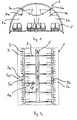
- FIG. 1 shows a section through an aircraft cabin 1, which is subdivided into a specific number of temperature zones 2.
- Fig. 1 for example, in the left half of a first temperature zone 2a and in the right half of a second temperature zone 2b are shown.
- Air outlets 3, the temperature zones 2 are supplied with air. Specifically, for example, air is blown into the temperature zone 2 a via the air outlet 3 a, and air is blown into the temperature zone 2 b via the air outlet 3 b.
- the air outlets 3a, 3b shown in Fig. 1 are arranged in the upper area (ceiling area) of the aircraft cabin, but may be formed at any other desired location within the cabin.
- sensors 4 for example temperature sensors 4a, 4b, which are respectively arranged in each temperature zone 2a, 2b in the upper region (ceiling region) of the cabin.
- the temperature sensors can be placed almost anywhere within the temperature zone.
- the sensor is positioned within the temperature zone 2 at a position which corresponds to the mean temperature of the temperature zone (not heat load). Of course, this temperature results from the heat loads within the temperature zone.
- the temperature is usually measured within a temperature zone 2 at the point that corresponds to the mean temperature in the zone. The resulting local temperatures are influenced by the occurring heat loads (sources and sinks).
- Fig. 1 also shows seats 5, for example, for receiving passengers.
- the temperature of this temperature zone 2 is greater than the temperature in an area of the cabin in which there are few or no occupied seats 5 (a small seating density) in an area of the aircraft cabin in which there are many passenger seats 5 , for example in the door area.
- the area with many seats then represents, for example, a heat source and the area on the door a heat sink.
- FIG. 2 shows a schematic view of an air distribution system in the aircraft cabin 1 shown in FIG. 1.
- This air distribution system has a main supply line 6, via which a plurality of air outlets 3 are supplied with air.
- the air outlet 3a shown in FIG. 1 is shown for simplicity.
- Each air outlet 3 is assigned to a specific temperature zone 2.
- the air outlet 3a thus supplies the temperature zone 2a with air.
- the main supply line 6 branch off a plurality of secondary supply lines 7 in order to supply the individual air outlets 3 each with air.
- the Heilausblasumble an air outlet 3 is defined by a corresponding supply him with air secondary supply line 7 and by an air gap within the air outlet to the outlet side of the air from the air outlet.
- only one group of air outlets 3 can communicate with the main supply line 6 via a single secondary supply line 7, so that Air is supplied via the main supply line 6 and the single secondary supply line 7 to the group of air outlets.
- Fig. 2 further shows a heating element 8 which is formed on the secondary supply line 7a, which supplies the air outlet 3a with air, which is blown heated in the temperature zone 2a, when the heating element 8 is in operation.
- the heating element 8 may be, for example, a heating coil, an electric heater or the like.
- the heating element may be located inside the sub-supply line 7a, so that an air flow flowing through the sub-supply line 7a comes into contact with the heating element 8 and thereby is effectively heated.
- the heating element 8 it is possible to mount the heating element 8 on the outside of the sub-supply line 7a, so that no direct contact with the air flowing in the sub-supply line 7a comes about. This has the advantage that the heating element 8 can be easily retrofitted without having to intervene in the piping system.
- the air heated by the heating element 8 is supplied to the air outlet 3a and blown through air nozzles 9a into the temperature zone 2a.
- Fig. 3 shows a schematic view of an air distribution system in the aircraft cabin shown in Fig. 1, according to an embodiment of the invention.
- a main supply line 6 branches into a left supply line 6a and a right supply line 6b.
- a group of air outlets is supplied with air (in the figure, only one air outlet 3a is shown for the sake of simplicity), the air outlets communicate directly with each other so that an air supply from the air outlet to the air outlet is ensured.
- Each air outlet 3 has air nozzles 9, is blown through the air in a temperature zone 2.
- a heating element 8 is located directly at an air outlet 3a in order to blow out heated air via air nozzles 9a.
- the heating element 8 may, for example, be integrally formed therewith on the air inlet side and / or air outlet side of the air outlet 3a in order to heat air only at the end of a blow-out path of the air outlet 3a.
- the heating element 8 may also be formed separately and inserted, for example, in the air nozzles 9a of the air outlet 3a, whereby an exchange and retrofitting of the heating element 8 is very easy.
- FIG. 2 and FIG. 3 only one heating element 8 is shown in each case by way of example. Depending on requirements, however, a plurality of air outlets 3 can each be assigned to one heating element 8 or a plurality of heating elements 8.
- the heating element 8 is then preferably assigned to an air outlet 3 to heat air in the blower section, if this Air outlet 3 is located in a so-called heat sink.
- a heat sink can be formed by a door area.
- the heating element can also be used as standard for all the air outlets 3, in order to appropriately temper the air blown out of the air outlets to a predetermined temperature, wherein the heating power of the heating elements can be designed differently.
- the heating power of a heating element which is located in the region of a heat sink, greater than that of a heating element, which is located in the region of a heat source.
- a heat source is formed for example by a high density of passengers.
- the heating element 8 may be, for example, a heating coil, an electric heater or the like, whose heating power is constant or adjustable, for example.
- the heating power is controlled by means of the temperature sensor 4 (sensors 4a and / or 4b) shown in FIG. 1 such that the blow-out path of an air outlet is heated in order to raise cold regions to the temperature level of the sensor point.
- the heating element 8 is formed on the air outlet side of the air outlet 3, so that the air blown out through the air nozzle 9 is heated.
- it may also be formed on an air inlet side of the air outlet 3.
- the heating element 8 extends only over part of the air nozzles 9.
- Fig. 5 shows a side view of the outlet shown in Fig. 4 from the right.
- the air outlet 3 is supplied from the right with air, which partially exits through the air nozzles 9 down and partially continues to the left, for example, to supply the downstream air outlets shown in Fig. 3.
- the downwardly branching from the supply air flow Luftausblasstrom (ie the Heilausblasumble) is heated by the formed directly on the air outlet 3 heating element 8, so that heated air is blown into a corresponding temperature zone 2, which is associated with this air outlet 3.
- the blow-out distance of the air outlet 3 is therefore heated by the heating element 8, so that heated air is blown into a temperature zone 2.
Landscapes
- Engineering & Computer Science (AREA)
- General Health & Medical Sciences (AREA)
- Aviation & Aerospace Engineering (AREA)
- Pulmonology (AREA)
- Health & Medical Sciences (AREA)
- Mechanical Engineering (AREA)
- Physics & Mathematics (AREA)
- Thermal Sciences (AREA)
- Air-Conditioning For Vehicles (AREA)
- Central Air Conditioning (AREA)
- Sampling And Sample Adjustment (AREA)
- Percussion Or Vibration Massage (AREA)
- Steam Or Hot-Water Central Heating Systems (AREA)
Description
- Die Erfindung betrifft eine Flugzeugkabine mit einem Luftverteilungssystem zur Homogenisierung einer Wärmelastverteilung innerhalb eines Raums,
- Um die Kabinentemperatur eines Flugzeugs zu regeln, ist die Kabine üblicherweise in eine bestimmte Anzahl von Temperaturzonen unterteilt. Es ist jedoch möglich, dass die Verteilung der Wärmequellen und -senken in der Zone inhomogen ist. Dies ist beispielsweise der Fall, wenn die Sitzdichte innerhalb der Zone variiert. Eine hohe Dichte an Passagieren bildet eine Wärmequelle, während ein leerer Türbereich eine Wärmesenke darstellt. Die Folge ist, dass in Bereichen mit einer Wärmequelle sich eine wärmere Temperatur und umgekehrt in einem Bereich mit Wärmesenken eine kältere Temperatur einstellt. Eine inhomogene Temperaturverteilung innerhalb der Zone bedeutet jedoch eine Einschränkung des thermischen Komforts.
- Ob es im einzelnen eine inhomogene Verteilung der Wärmequellen und -senken gibt hängt also von der individuellen Gestaltung des Sitzlayouts ab. Dieses kann für jeden Flugzeugkunden unterschiedlich aussehen.
- Um der Inhomogenität der Wärmelastverteilung innerhalb einer Temperaturzone entgegenzuwirken, wird üblicherweise die Einblasmenge durch Luftauslässe an den Stellen mit zu kalter Zuluft-Temperatur reduziert, wodurch das Temperaturniveau des entsprechenden Kabinenteils angehoben wird. Ein Nachteil der Reduzierung der Luftmenge liegt jedoch darin, dass das Luftverteilungssystem neu kalibriert werden muss, was mit einem großen zeitlichen Aufwand verbunden ist.
- Die
DE 43 35 152 C1 offenbart ein Kabinenumluftsystem zur Klimatisierung von Rumpfeinheiten eines Passagierflugzeuges. Dieses Kabinenumluftsystem regelt den Frischluftmengenstrom inklusive die Temperaturüberwachung für den Druckrumpf eines Passagierflugzeuges und gewährt einen hohen Reinheitsgrad der klimatisierten Luft. Die Temperaturregelung erfolgt durch separate Wärmetauscher in der Zirkulationsluft. - Die
DE 195 09 773 C1 offenbart ein Belüftungssystem zur Verminderung der Konzentration von Verunreinigungen im Passagierbereich, insbesondere in den Raucherzonen. - Die
DE 44 25 871 C2 offenbart ein Verfahren zum Klimatisieren von zwei Passagierdecks eines Flugzeugs. Zur Temperatureinstellung werden jeweils Klimaaggregate für einen Oberdeckkreislauf und einen Hauptdeckkreislauf verwendet. In jeweiligen Klimaaggregaten wird die von den Triebwerken entnommene Zapfluft gekühlt. Die Klimaaggregate sind ferner an eine Außenluftleitung angeschlossen, um während des Betriebs die heiße Zapfluft vom Triebwerk mit Außenluft zu kühlen. -
US 2003/0141413 A1 offenbart ein Umweltkontrollsystem für ein Flugzeug mit einer Hauptluftversorgung und Einzelauslässen. In die Einzelauslässe sind nahe der Hauptverteilungsleitung und fern von den tatsächlichen Auslässen zu den Schlafplätzen für die Crew Heizelemente angeordnet. -
US 3,067,318 offenbart ein elektrisches Heizsystem, in dem Ventilatoren vorgesehen sind, um Luft in einen Raum einzublasen. Entfernt von den Ventilatoren, d. h. zwischen einer Hauptversorgungsleitung und den Ventilatoren sind Heizeinrichtungen vorgesehen. - Aufgabe der Erfindung ist die Schaffung eine Flugzeugkabine mit einer homogenen Temperaturverteilung.
- Die Lösung der gestellten Aufgabe ist dem Patentanspruch 1 zu entnehmen. Vorteilhafte Ausgestaltungen der Erfindung sind in den Unteransprüchen angegeben.
- Im folgenden werden bevorzugte Ausführungsbeispiele der Erfindung unter Bezugnahme auf die beigefügten Figuren beschrieben. Es zeigen:
- Fig. 1 einen Querschnitt durch eine Flugzeugkabine;
- Fig. 2 eine schematische Ansicht einer Luftverteilung in der in Fig. 1 gezeigten Flugzeugkabine;
- Fig. 3 eine schematische Ansicht der Luftverteilung in der in Fig. 1 gezeigten Flugzeugkabine gemäß einem Ausführungsbeispiel der Erfindung;
- Fig. 4 einen Einbauort für die Beheizung bei der in Fig. 3 gezeigten Luftverteilung; und
- Fig. 5 eine Seitenansicht des in Fig. 4 gezeigten Luftauslasses von rechts.
- In den Figuren werden gleiche oder ähnliche Elemente mit gleichen Bezugszeichen versehen.
- Fig. 1 zeigt einen Schnitt durch eine Flugzeugkabine 1, die in eine bestimmte Anzahl von Temperaturzonen 2 unterteilt ist. In Fig. 1 sind beispielsweise in der linken Hälfte eine erste Temperaturzone 2a und in der rechten Hälfte eine zweite Temperaturzone 2b gezeigt.
- Über Luftauslässe 3 werden die Temperaturzonen 2 mit Luft versorgt. Speziell wird beispielsweise über den Luftauslass 3a Luft in die Temperaturzone 2a eingeblasen, und über den Luftauslass 3b wird Luft in die Temperaturzone 2b eingeblasen.
- Die in Fig. 1 gezeigten Luftauslässe 3a, 3b sind im oberen Bereich (Deckenbereich) der Flugzeugkabine angeordnet, können jedoch an irgendeiner anderen gewünschten Stelle innerhalb der Kabine gebildet sein.
- Fig. 1 zeigt ferner Sensoren 4, beispielsweise Temperatursensoren 4a, 4b, die jeweils in jeder Temperaturzone 2a, 2b im oberen Bereich (Deckenbereich) der Kabine angeordnet sind. Die Temperatursensoren können alternativ fast an beliebigen Stellen innerhalb der Temperaturzone angeordnet werden. Vorteilhaft wird der Sensor innerhalb der Temperaturzone 2 an einer Stelle positioniert, die der mittleren Temperatur der Temperaturzone (nicht Wärmelast) entspricht. Diese Temperatur resultiert natürlich aus den Wärmelasten innerhalb der Temperaturzone. Mit diesen Temperatursensoren 4a, 4b wird innerhalb einer Temperaturzone 2 die Temperatur üblicherweise an der Stelle gemessen, die der mittleren Temperatur in der Zone entspricht. Die sich einstellenden lokalen Temperaturen werden dabei durch die auftretenden Wärmelasten (Quellen und Senken) beinflusst.
- Fig. 1 zeigt ferner Sitze 5, beispielsweise zur Aufnahme von Passagieren. In einem Bereich der Flugzeugkabine, in dem sich viele mit Passagieren belegte Sitze 5 befinden, ist im allgemeinen die Temperatur dieser Temperaturzone 2 größer als die Temperatur in einem Bereich der Kabine, in dem sich wenige oder keine belegten Sitzplätze 5 (eine geringe Sitzplatzdichte) befinden, beispielsweise im Bereich der Tür. Der Bereich mit vielen Sitzen stellt dann beispielsweise eine Wärmequelle dar und der Bereich an der Tür eine Wärmesenke.
- Fig. 2 zeigt eine schematische Ansicht eines Luftverteilungssystems in der in Fig. 1 gezeigten Flugzeugkabine 1. Dieses Luftverteilungssystem weist eine Hauptversorgungsleitung 6 auf, über die mehrere Luftauslässe 3 mit Luft versorgt werden. In der Figur ist zur Vereinfachung der Luftauslass 3a gemäß Fig. 1 dargestellt. Jeder Luftauslass 3 ist einer bestimmten Temperaturzone 2 zugeordnet. Der Luftauslass 3a versorgt also die Temperaturzone 2a mit Luft.
- Von der Hauptversorgungsleitung 6 zweigen eine Mehrzahl von Nebenversorgungsleitungen 7 ab, um die einzelnen Luftauslässe 3 jeweils mit Luft zu versorgen. Dabei ist die Luftausblasstrecke eines Luftauslasses 3 durch eine entsprechende ihn mit Luft versorgende Nebenversorgungsleitung 7 und durch eine Luftstrecke innerhalb des Luftauslasses bis zur Austrittsseite der Luft aus dem Luftauslass definiert.
- Alternativ kann auch nur eine Gruppe von Luftauslässen 3 über eine einzige Nebenversorgungsleitung 7 mit der Hauptversorgungsleitung 6 in Verbindung stehen, so dass Luft über die Hauptversorgungsleitung 6 und die einzelne Nebenversorgungsleitung 7 an die Gruppe von Luftauslässen geliefert wird.
- Fig. 2 zeigt ferner ein Heizelement 8, welches an der Nebenversorgungsleitung 7a ausgebildet ist, die den Luftauslass 3a mit Luft versorgt, die in die Temperaturzone 2a erwärmt eingeblasen wird, wenn das Heizelement 8 in Betrieb ist.
- Das Heizelement 8 kann beispielsweise eine Heizwendel, eine elektrische Heizung oder dergleichen sein. Das Heizelement kann sich innerhalb der Nebenversorgungsleitung 7a befinden, so dass ein durch die Nebenversorgungsleitung 7a strömender Luftstrom mit dem Heizelement 8 in Kontakt kommt und dadurch in effektiver Weise erwärmt wird.
- Alternativ ist es möglich, das Heizelement 8 außen auf der Nebenversorgungsleitung 7a anzubringen, so dass kein direkter Kontakt mit der in der Nebenversorgungsleitung 7a strömenden Luft zustande kommt. Dies hat den Vorteil, dass das Heizelement 8 leicht nachträglich eingebaut werden kann, ohne in das Rohrleitungssystem eingreifen zu müssen.
- Die von dem Heizelement 8 erwärmte Luft wird an den Luftauslass 3a geliefert und über Luftdüsen 9a in die Temperaturzone 2a auszublasen.
- Fig. 3 zeigt eine schematische Ansicht eines Luftverteilungssystems in der in Fig. 1 gezeigten Flugzeugkabine, gemäß einem Ausführungsbeispiel der Erfindung.
- Bei diesem Luftverteilungssystem zweigt sich eine Hauptversorgungsleitung 6 in eine linke Versorgungsleitung 6a und in eine rechte Versorgungsleitung 6b. Über die linke Versorgungsleitung 6a wird eine Gruppe von Luftauslässen mit Luft versorgt (in der Figur ist zur Vereinfachung lediglich ein Luftauslass 3a dargestellt), wobei die Luftauslässe untereinander direkt in Verbindung stehen, so dass eine Luftversorgung von Luftauslass zu Luftauslass sicher gestellt ist. Jeder Luftauslass 3 weist Luftdüsen 9 auf, über die Luft in eine Temperaturzone 2 ausgeblasen wird.
- Im Gegensatz zu Fig. 2 befindet sich ein Heizelement 8 unmittelbar an einem Luftauslass 3a, um über Luftdüsen 9a erwärmte Luft auszublasen. Das Heizelement 8 kann beispielsweise auf der Lufteintrittsseite und/oder Luftaustrittsseite des Luftauslasses 3a mit diesem integriert ausgebildet sein, um Luft erst am Ende einer Ausblasstrecke des Luftauslasses 3a zu erwärmen. Dadurch kann ein Heizelement mit weniger Heizleistung verwendet werden, verglichen mit dem ersten Ausführungsbeispiel, bei dem Luft bereits relativ am Anfang einer Ausblasstrecke erwärmt wird.
- Das Heizelement 8 kann auch separat gebildet sein und beispielsweise in die Luftdüsen 9a des Luftauslasses 3a eingesteckt werde, wodurch ein Austausch und ein nachträgliches Einbauen des Heizelements 8 sehr einfach wird.
- Wie in Fig. 3 gezeigt, ist nur der Luftauslass 3a mit einem Heizelement 8 versehen, so dass nur die von diesem Luftauslass ausgeblasene Luft erwärmt ist, und in Bezug auf den Versorgungsluftstrom stromaufwärts und stromabwärts liegende Luftauslässe 3 nicht beeinflusst werden, also eine durch diese Luftauslässe ausgeblasene Luft nicht erwärmt ist.
- In Fig. 2 und Fig. 3 ist jeweils beispielhaft nur ein Heizelement 8 gezeigt. Je nach Bedarf können jedoch auch mehrere Luftauslässe 3 jeweils einem Heizelement 8 oder mehreren Heizelementen 8 zugeordnet sein. Das Heizelement 8 ist vorzugsweise dann einem Luftauslass 3 zuzuordnen, um Luft in dessen Ausblasstrecke zu erwärmen, wenn dieser Luftauslass 3 in einer sogenannten Wärmesenke liegt. Eine derartige Wärmesenke kann durch einen Türbereich gebildet werden.
- Zusätzlich kann das Heizelement auch standardmäßig für sämtliche Luftauslässe 3 verwendet werden, um die aus den Luftauslässen ausgeblasene Luft auf eine vorbestimmte Temperatur entsprechend zu temperieren, wobei die Heizleistung der Heizelemente unterschiedlich ausgelegt sein kann. Vorzugsweise ist die Heizleistung eines Heizelements, welches sich im Bereich einer Wärmesenke befindet, größer als die eines Heizelements, welches sich im Bereich einer Wärmequelle befindet. Eine Wärmequelle wird beispielsweise durch eine hohe Dichte an Passagieren gebildet.
- Das Heizelement 8 kann beispielsweise eine Heizwendel, eine elektrische Heizung oder dergleichen sein, dessen Heizleistung beispielsweise konstant oder einstellbar ist.
- Vorzugsweise wird die Heizleistung mit Hilfe des in Fig. 1 gezeigten Temperatursensors 4 (Sensoren 4a und/oder 4b) derart geregelt, dass die Ausblasstrecke eines Luftauslasses beheizt wird, um zu kalte Bereiche an das Temperaturniveau des Sensorpunktes anzuheben.
- Fig. 4 zeigt einen möglichen Einbauort für das Heizelement 8.
- Gemäß diesem Ausführungsbeispiel ist das Heizelement 8 an der Luftaustrittsseite des Luftauslasses 3 ausgebildet, so dass die durch die Luftdüse 9 ausgeblasene Luft erwärmt ist. Es kann jedoch auch an einer Lufteintrittsseite des Luftauslasses 3 ausgebildet werden.
- Wenn der Luftauslass 3 mehrere Luftdüsen 9 aufweist, ist es möglich, dass sich das Heizelement 8 nur über einen Teil der Luftdüsen 9 erstreckt.
- Fig. 5 zeigt eine Seitenansicht des in Fig. 4 gezeigten Auslasses von rechts. Wie in Fig. 5 gezeigt, wird der Luftauslass 3 von rechts mit Luft beliefert, die zum Teil über die Luftdüsen 9 nach unten austritt und zum Teil nach links weiterströmt, um beispielsweise die in Fig. 3 gezeigten stromabwärts liegenden Luftauslässe zu versorgen. Der von dem Versorgungsluftstrom nach unten abzweigende Luftausblasstrom (also die Luftausblasstrecke) wird durch das unmittelbar am Luftauslass 3 ausgebildete Heizelement 8 erwärmt, so dass erwärmte Luft in eine entsprechende Temperaturzone 2, die diesem Luftauslass 3 zugeordnet ist, ausgeblasen wird.
- Die Ausblasstrecke des Luftauslasses 3 wird also durch das Heizelement 8 beheizt, so dass erwärmte Luft in eine Temperaturzone 2 geblasen wird.
Claims (5)
- Flugzeugkabine mit einem Luftverteilungssystem, wobei das Luftverteilungssystem eine Hauptversorgungsleitung (6),
eine Mehrzahl von Luftauslässen (3), die über Nebenverteilungsleitungen (7) an die Hauptverteilungsleitung (6) angeschlossen sind und
mindestens ein Heizelement (8) aufweist,
dadurch gekennzeichnet, daß
das mindestens eine Heizelement unmittelbar an einem der Luftauslässe (3) angeordnet ist zur Temperierung der Luft an der Luftaustrittsseite dieses Luftauslasses;
wobei das mindestens eine Heizelement (8) im Bereich einer Tür in der Kabine angeordnet ist. - Flugzeugkabine mit einem Luftverteilungssystem nach Anspruch 1, bei dem eine Luftversorgung von Luftauslass (3) zu Luftauslass (3) sichergestellt ist.
- Flugzeugkabine mit einem Luftverteilungssystem nach einem der vorangegangenen Ansprüche, bei dem das Heizelement (8) eine konstante einstellbare Heizleistung aufweist.
- Flugzeugkabine mit einem Luftverteilungssystem nach Anspruch 1 oder 2, mit mindestens einem Temperatursensor (4a, 4b) mit dem die Heizleistung des Heizelements (8) auf einen vorbestimmten Wert regelbar ist.
- Flugzeugkabine mit einem Luftverteilungssystem nach einem der vorangegangenen Ansprüche, bei dem die in dem Luftverteilungssystem fließende Luftmenge im wesentlichen konstant bleibt.
Applications Claiming Priority (2)
| Application Number | Priority Date | Filing Date | Title |
|---|---|---|---|
| DE10361392A DE10361392B4 (de) | 2003-12-29 | 2003-12-29 | Luftverteilungssystem |
| DE10361392 | 2003-12-29 |
Publications (2)
| Publication Number | Publication Date |
|---|---|
| EP1550569A1 EP1550569A1 (de) | 2005-07-06 |
| EP1550569B1 true EP1550569B1 (de) | 2007-07-25 |
Family
ID=34559774
Family Applications (1)
| Application Number | Title | Priority Date | Filing Date |
|---|---|---|---|
| EP04030273A Expired - Lifetime EP1550569B1 (de) | 2003-12-29 | 2004-12-21 | Luftverteilungssystem |
Country Status (5)
| Country | Link |
|---|---|
| US (1) | US20050230488A1 (de) |
| EP (1) | EP1550569B1 (de) |
| AT (1) | ATE367941T1 (de) |
| CA (1) | CA2490588C (de) |
| DE (2) | DE10361392B4 (de) |
Families Citing this family (10)
| Publication number | Priority date | Publication date | Assignee | Title |
|---|---|---|---|---|
| DE102006005037B4 (de) | 2006-02-03 | 2012-03-29 | Airbus Operations Gmbh | Klimatisierungsanordnung für ein Flugzeug mit mehreren individuell temperaturregelbaren Klimazonen |
| DE102007019539B4 (de) * | 2007-04-25 | 2012-12-13 | Airbus Operations Gmbh | Luftzufuhrvorrichtung für die Klimatisierung von Passagierräumen in Flugzeugen |
| US9561855B2 (en) * | 2008-05-01 | 2017-02-07 | The Boeing Company | Alternate directional momentum ventilation nozzle for passenger cabins |
| DE102008050546B4 (de) | 2008-10-06 | 2012-03-08 | Airbus Operations Gmbh | Side-Feeder-Luftführungselement für eine Flugzeugklimaanlage |
| DE102008052792B4 (de) * | 2008-10-22 | 2010-11-04 | Airbus Deutschland Gmbh | Luftführungselement und Luftführungselementanordnung für eine Flugzeugklimaanlage |
| CA2826476C (en) * | 2011-02-04 | 2015-06-23 | Bombardier Transportation Gmbh | A ventilation system for a passenger transit vehicle |
| DE102011121053A1 (de) * | 2011-12-14 | 2013-06-20 | Airbus Operations Gmbh | Temperaturregelung von beheizten Luftverteilungssystemen in Passagierräumen |
| US20200377216A1 (en) * | 2019-05-31 | 2020-12-03 | Hamilton Sundstrand Corporation | Aircraft cabin air thermodynamic control |
| US12392529B2 (en) * | 2020-04-13 | 2025-08-19 | The Boeing Company | Air distribution system and method including a thermocouple device |
| EP4570664A1 (de) * | 2023-12-14 | 2025-06-18 | Airbus Operations GmbH | Flugzeugkabinenbelüftungssystem mit verbesserter belüftung |
Family Cites Families (65)
| Publication number | Priority date | Publication date | Assignee | Title |
|---|---|---|---|---|
| US1391113A (en) * | 1920-08-27 | 1921-09-20 | Andrew J Holmes | Electric heater |
| US1909144A (en) * | 1930-05-29 | 1933-05-16 | Burd High Compression Ring Com | Heater |
| US2218468A (en) * | 1937-02-23 | 1940-10-15 | Honeywell Regulator Co | Air conditioning system |
| US2260900A (en) * | 1937-12-30 | 1941-10-28 | Gen Motors Corp | Air conditioning |
| US2199840A (en) * | 1939-01-14 | 1940-05-07 | Royall Ralph | Heating system |
| US2242630A (en) * | 1940-02-09 | 1941-05-20 | Steingruber George | Electric heater |
| US2341439A (en) * | 1942-05-06 | 1944-02-08 | Alfred L Greenlaw | Grill |
| US2429619A (en) * | 1943-01-21 | 1947-10-28 | Clyde M Hamblin | Air conditioning system |
| US2412110A (en) * | 1943-02-04 | 1946-12-03 | Stewart Warner Corp | Air conditioning apparatus for aircraft |
| US2357112A (en) * | 1943-04-02 | 1944-08-29 | Stewart Warner Corp | Airplane heating system |
| US2427698A (en) * | 1944-04-28 | 1947-09-23 | Solar Aircraft Co | Insulating and ventilating structure |
| US2565769A (en) * | 1949-03-02 | 1951-08-28 | Tennessee Valley Authority | Electric heater |
| US2760725A (en) * | 1951-01-03 | 1956-08-28 | Budd Co | Thermal conditioning and ventilating means and method |
| US2706942A (en) * | 1951-06-27 | 1955-04-26 | William J Caldwell | Rifled air control nozzles |
| US2980785A (en) * | 1959-03-30 | 1961-04-18 | Nicholas E Whitney Sr | Electric heating |
| US3067316A (en) * | 1960-05-20 | 1962-12-04 | Worthington Corp | Electrical duct heater |
| US3203473A (en) * | 1960-10-05 | 1965-08-31 | Lockheed Aircraft Corp | Aircraft heating system |
| US3111571A (en) * | 1962-01-26 | 1963-11-19 | Williamson Company | Electric heating unit |
| US3697728A (en) * | 1968-12-13 | 1972-10-10 | Air Plastic Service Gmbh | Heating devices |
| US3482503A (en) * | 1968-12-20 | 1969-12-09 | Jenn Air Corp | System for comfort conditioning structures |
| US3605797A (en) * | 1970-05-18 | 1971-09-20 | Dunham Bush Inc | Shut off damper assembly for high velocity ducted air type conditioning system |
| US3687054A (en) * | 1970-11-24 | 1972-08-29 | Lockheed Aircraft Corp | Air outlet apparatus |
| US3799046A (en) * | 1972-04-06 | 1974-03-26 | Mitco Corp | Diffuser valve |
| US3951205A (en) * | 1972-08-18 | 1976-04-20 | Brandt Engineering Co. | Air-conditioning apparatus |
| US3974752A (en) * | 1974-11-25 | 1976-08-17 | The Garrett Corporation | Pressure control system |
| DE2834256C2 (de) * | 1978-08-04 | 1985-05-23 | Messerschmitt-Bölkow-Blohm GmbH, 8012 Ottobrunn | Anordnung zur Klimatisierung von Luftfahrzeugkabinen |
| US4232211A (en) * | 1978-10-19 | 1980-11-04 | Hill Johnnie L | Automobile auxiliary heater |
| US4263786A (en) * | 1979-07-10 | 1981-04-28 | The Boeing Company | Fuel conserving air-conditioning apparatus and method for aircraft |
| US4446774A (en) * | 1980-05-19 | 1984-05-08 | Gershon Meckler | Air conditioning apparatus |
| US4473107A (en) * | 1981-08-19 | 1984-09-25 | Building Facilities Corporation | Fan/coil induction unit, system, and method |
| US4505124A (en) * | 1983-09-22 | 1985-03-19 | The United States Of America As Represented By The Secretary Of The Air Force | Heat management system for aircraft |
| US4513574A (en) * | 1984-04-30 | 1985-04-30 | Tempmaster Corporation | Low Temperature air conditioning system and method |
| IT8553106U1 (it) * | 1985-03-08 | 1986-09-08 | Foggini Progetti | Bocchetta di erogazione d'aria di climatizzazione per autoveicoli, incorporante mezzi elettrici di riscaldamento |
| JPS6262511U (de) * | 1985-10-11 | 1987-04-18 | ||
| US4814579A (en) * | 1986-04-07 | 1989-03-21 | Innovative Scientific Development, Inc. | Electric resistance air reating system for an aircraft cabin |
| US4819548A (en) * | 1987-05-07 | 1989-04-11 | The Boeing Company | Dual nozzle cabin ventilation system |
| US4742760A (en) * | 1987-07-06 | 1988-05-10 | The Boeing Company | Aircraft cabin ventilation system |
| US4742761A (en) * | 1987-07-20 | 1988-05-10 | The Boeing Company | Method and apparatus for controlling the concentration of carbon dioxide in an aircraft cabin |
| CA1298600C (en) * | 1988-10-24 | 1992-04-07 | Joseph Ghorayeb | Radiator humidifier |
| KR930006392A (ko) * | 1991-09-02 | 1993-04-21 | 이우에 사또시 | 공기 조화기 |
| US5423498A (en) * | 1993-04-27 | 1995-06-13 | E-Systems, Inc. | Modular liquid skin heat exchanger |
| DE4316886C2 (de) * | 1993-05-19 | 1995-05-18 | Nord Micro Elektronik Feinmech | Kabinendruckregelanlage für Flugzeuge |
| DE4335152C1 (de) * | 1993-10-15 | 1995-04-20 | Deutsche Aerospace Airbus | Kabinenumluftsystem zur Klimatisierung von Rumpfeinheiten eines Passagierflugzeuges |
| DE4425871C2 (de) * | 1994-07-21 | 1998-07-02 | Daimler Benz Aerospace Airbus | Verfahren zum Klimatisieren von zwei Passagierdecks eines Flugzeuges, insbesondere eines Großraumflugzeuges, und Einrichtung zur Durchführung des Verfahrens |
| US5533568A (en) * | 1994-11-08 | 1996-07-09 | Carrier Corporation | Managing supplementary heat during defrost on heat pumps |
| CA2140232C (en) * | 1995-01-13 | 2004-04-13 | Peter Karl Grinbergs | Heat recovery ventilator |
| DE19509773C1 (de) * | 1995-03-17 | 1996-06-27 | Daimler Benz Aerospace Airbus | Belüftungssystem zur Verminderung der Konzentration von Verunreinigungen im Flugzeugpassagierbereich |
| US5704218A (en) * | 1996-04-08 | 1998-01-06 | United Technologies Corporation | Integrated environmental control system |
| US5760376A (en) * | 1996-06-19 | 1998-06-02 | Cox 3 Company, Inc. | Air heater with self-supporting heater element |
| US5701755A (en) * | 1997-01-15 | 1997-12-30 | Sundstrand Corporation | Cooling of aircraft electronic heat loads |
| DE19728595C1 (de) * | 1997-07-04 | 1998-09-17 | Daimler Benz Aerospace Airbus | Injektorluftauslaß zur Temperatur- und Rauchgasüberwachung |
| US5897079A (en) * | 1997-08-18 | 1999-04-27 | Mcdonnell Douglas Corporation | Air curtain insulating system for aircraft cabin |
| JPH11159782A (ja) * | 1997-11-28 | 1999-06-15 | Mitsubishi Electric Corp | 温風装置 |
| GB9804784D0 (en) * | 1998-03-06 | 1998-04-29 | Rolls Royce Plc | Environmental control system |
| DE59904160D1 (de) * | 1998-03-26 | 2003-03-06 | Fraunhofer Ges Forschung | Verfahren und vorrichtung zur klimatisierung von fahrzeugen und insbesondere von flugzeugen |
| US6510696B2 (en) * | 1998-06-15 | 2003-01-28 | Entrosys Ltd. | Thermoelectric air-condition apparatus |
| DE19936641C2 (de) * | 1999-08-04 | 2001-06-13 | Eads Airbus Gmbh | Vorrichtung zur Klimatisierung von Passagierflugzeugen |
| US6413159B1 (en) * | 2000-06-28 | 2002-07-02 | The Boeing Company | Airplane cabin overhead air outlets |
| US6393717B1 (en) * | 2001-01-24 | 2002-05-28 | Victor M. Santos | Foot dryer device with diffused heated air flow system |
| DE10121906B4 (de) * | 2001-05-03 | 2006-12-14 | Saia-Burgess Ozd Kft. | Belüftungsvorrichtung für Fahrzeuge |
| KR100423972B1 (ko) * | 2001-11-30 | 2004-03-22 | 삼성전자주식회사 | 공기조화기 및 그 제어방법 |
| US6619589B2 (en) * | 2002-01-28 | 2003-09-16 | The Boeing Company | Flight crew and attendant rest environmental control system |
| US6672541B2 (en) * | 2002-01-28 | 2004-01-06 | The Boeing Company | Flight crew rest and attendant rest environmental control system |
| US6694765B1 (en) * | 2002-07-30 | 2004-02-24 | Thermo King Corporation | Method and apparatus for moving air through a heat exchanger |
| US7203416B2 (en) * | 2003-11-21 | 2007-04-10 | Broan-Nutone Llc | Ventilating and heating apparatus with heater shielded by tapered discharge duct |
-
2003
- 2003-12-29 DE DE10361392A patent/DE10361392B4/de not_active Expired - Fee Related
-
2004
- 2004-12-21 AT AT04030273T patent/ATE367941T1/de not_active IP Right Cessation
- 2004-12-21 EP EP04030273A patent/EP1550569B1/de not_active Expired - Lifetime
- 2004-12-21 CA CA2490588A patent/CA2490588C/en not_active Expired - Fee Related
- 2004-12-21 DE DE502004004424T patent/DE502004004424D1/de not_active Expired - Lifetime
- 2004-12-23 US US11/020,617 patent/US20050230488A1/en not_active Abandoned
Also Published As
| Publication number | Publication date |
|---|---|
| CA2490588C (en) | 2013-01-29 |
| DE10361392A1 (de) | 2005-07-28 |
| ATE367941T1 (de) | 2007-08-15 |
| DE502004004424D1 (de) | 2007-09-06 |
| DE10361392B4 (de) | 2009-07-30 |
| CA2490588A1 (en) | 2005-06-29 |
| US20050230488A1 (en) | 2005-10-20 |
| EP1550569A1 (de) | 2005-07-06 |
Similar Documents
| Publication | Publication Date | Title |
|---|---|---|
| DE60000741T2 (de) | Verbesserungen an einen kühlofen für flachglas | |
| DE102006041030B4 (de) | Luftfahrzeug-Klimatisierungssystem zum individuellen Klimatisieren von Bereichen einer Luftfahrzeugkabine mit einem flüssigen Kühlmittel | |
| DE102017210042B4 (de) | Belüfteter Sitz, Fahrzeug und Verfahren zur Belüftung eines Sitzes | |
| DE10361392B4 (de) | Luftverteilungssystem | |
| DE102007002538B4 (de) | Flexible Luftfahrzeugklimaanlage für eine flexibel unterteilbare Luftfahrzeugkabine | |
| DE10361688B4 (de) | Vorrichtung zur Steuerung der Versorgungslufttemperatur eines Passagierflugzeugs | |
| EP2536632A1 (de) | Zuluftversorgung für passagiere in flugzeugen | |
| DE102019122963A1 (de) | Flugzeugkabine und Flugzeugkabinen-Kühleinrichtung | |
| DE102011121053A1 (de) | Temperaturregelung von beheizten Luftverteilungssystemen in Passagierräumen | |
| DE60221007T2 (de) | Heizungs-, belüftungs- und/oder klimaanlagen | |
| DE102006037539B4 (de) | Klimatisierungssystem mit Vereisungsschutz für ein Luftfahrzeug | |
| EP3902730B1 (de) | Fahrzeug | |
| DE3514359A1 (de) | Vorrichtung zum beheizen und/oder klimatisieren des innenraums eines fahrzeuges | |
| DE102014109925A1 (de) | Mehrzonen-Klimatisierungseinrichtung | |
| DE10361637A1 (de) | Verfahren und Vorrichtung zum Klimatisieren eines Frachtraumes oder einer Kabine eines Flugzeugs | |
| EP1237742B1 (de) | Heiz- und/oder klimaanlage für ein fahrzeug mit teilluftführungskanal | |
| DE19711033A1 (de) | Heizungs-, Lüftungs- und/oder Klimaanlage mit Temperaturregelung, insbesondere für Kraftfahrzeuge | |
| DE102011121721A1 (de) | Mischvorrichtung mit verringerter Vereisungsgefahr | |
| DE2613608B2 (de) | Einkanal-Klimaanlage für Schienenfahrzeuge | |
| DE3520553C2 (de) | ||
| DE102007042565A1 (de) | Klimaanlage für ein Fahrzeug mit einem multifunktionalen Anschluss und ein Kombinationsanschluss | |
| DE102024205715A1 (de) | Zuluftsystem, Klimatisierungssystem und spurgeführtes Fahrzeug | |
| DE102010051969A1 (de) | Anordnung zum Heizen eines Fahrgastraums | |
| DE102004045777A1 (de) | Verfahren und Vorrichtung zum Klimatisieren eines Frachtraumes oder einer Kabine eines Flugzeugs | |
| DE102021209682A1 (de) | Wärme/Kälte-Übertrager |
Legal Events
| Date | Code | Title | Description |
|---|---|---|---|
| PUAI | Public reference made under article 153(3) epc to a published international application that has entered the european phase |
Free format text: ORIGINAL CODE: 0009012 |
|
| AK | Designated contracting states |
Kind code of ref document: A1 Designated state(s): AT BE BG CH CY CZ DE DK EE ES FI FR GB GR HU IE IS IT LI LT LU MC NL PL PT RO SE SI SK TR |
|
| AX | Request for extension of the european patent |
Extension state: AL BA HR LV MK YU |
|
| 17P | Request for examination filed |
Effective date: 20051020 |
|
| AKX | Designation fees paid |
Designated state(s): AT BE BG CH CY CZ DE DK EE ES FI FR GB GR HU IE IS IT LI LT LU MC NL PL PT RO SE SI SK TR |
|
| GRAP | Despatch of communication of intention to grant a patent |
Free format text: ORIGINAL CODE: EPIDOSNIGR1 |
|
| GRAS | Grant fee paid |
Free format text: ORIGINAL CODE: EPIDOSNIGR3 |
|
| GRAA | (expected) grant |
Free format text: ORIGINAL CODE: 0009210 |
|
| AK | Designated contracting states |
Kind code of ref document: B1 Designated state(s): AT BE BG CH CY CZ DE DK EE ES FI FR GB GR HU IE IS IT LI LT LU MC NL PL PT RO SE SI SK TR |
|
| REG | Reference to a national code |
Ref country code: GB Ref legal event code: FG4D Free format text: NOT ENGLISH |
|
| REG | Reference to a national code |
Ref country code: CH Ref legal event code: EP |
|
| REG | Reference to a national code |
Ref country code: IE Ref legal event code: FG4D Free format text: LANGUAGE OF EP DOCUMENT: GERMAN |
|
| REF | Corresponds to: |
Ref document number: 502004004424 Country of ref document: DE Date of ref document: 20070906 Kind code of ref document: P |
|
| REG | Reference to a national code |
Ref country code: SE Ref legal event code: TRGR |
|
| GBT | Gb: translation of ep patent filed (gb section 77(6)(a)/1977) |
Effective date: 20071004 |
|
| ET | Fr: translation filed | ||
| PG25 | Lapsed in a contracting state [announced via postgrant information from national office to epo] |
Ref country code: NL Free format text: LAPSE BECAUSE OF FAILURE TO SUBMIT A TRANSLATION OF THE DESCRIPTION OR TO PAY THE FEE WITHIN THE PRESCRIBED TIME-LIMIT Effective date: 20070725 Ref country code: FI Free format text: LAPSE BECAUSE OF FAILURE TO SUBMIT A TRANSLATION OF THE DESCRIPTION OR TO PAY THE FEE WITHIN THE PRESCRIBED TIME-LIMIT Effective date: 20070725 Ref country code: BG Free format text: LAPSE BECAUSE OF FAILURE TO SUBMIT A TRANSLATION OF THE DESCRIPTION OR TO PAY THE FEE WITHIN THE PRESCRIBED TIME-LIMIT Effective date: 20071025 Ref country code: LT Free format text: LAPSE BECAUSE OF FAILURE TO SUBMIT A TRANSLATION OF THE DESCRIPTION OR TO PAY THE FEE WITHIN THE PRESCRIBED TIME-LIMIT Effective date: 20070725 Ref country code: PT Free format text: LAPSE BECAUSE OF FAILURE TO SUBMIT A TRANSLATION OF THE DESCRIPTION OR TO PAY THE FEE WITHIN THE PRESCRIBED TIME-LIMIT Effective date: 20071226 Ref country code: IS Free format text: LAPSE BECAUSE OF FAILURE TO SUBMIT A TRANSLATION OF THE DESCRIPTION OR TO PAY THE FEE WITHIN THE PRESCRIBED TIME-LIMIT Effective date: 20071125 Ref country code: ES Free format text: LAPSE BECAUSE OF FAILURE TO SUBMIT A TRANSLATION OF THE DESCRIPTION OR TO PAY THE FEE WITHIN THE PRESCRIBED TIME-LIMIT Effective date: 20071105 |
|
| NLV1 | Nl: lapsed or annulled due to failure to fulfill the requirements of art. 29p and 29m of the patents act | ||
| PG25 | Lapsed in a contracting state [announced via postgrant information from national office to epo] |
Ref country code: PL Free format text: LAPSE BECAUSE OF FAILURE TO SUBMIT A TRANSLATION OF THE DESCRIPTION OR TO PAY THE FEE WITHIN THE PRESCRIBED TIME-LIMIT Effective date: 20070725 |
|
| REG | Reference to a national code |
Ref country code: IE Ref legal event code: FD4D |
|
| PG25 | Lapsed in a contracting state [announced via postgrant information from national office to epo] |
Ref country code: GR Free format text: LAPSE BECAUSE OF FAILURE TO SUBMIT A TRANSLATION OF THE DESCRIPTION OR TO PAY THE FEE WITHIN THE PRESCRIBED TIME-LIMIT Effective date: 20071026 Ref country code: DK Free format text: LAPSE BECAUSE OF FAILURE TO SUBMIT A TRANSLATION OF THE DESCRIPTION OR TO PAY THE FEE WITHIN THE PRESCRIBED TIME-LIMIT Effective date: 20070725 |
|
| PG25 | Lapsed in a contracting state [announced via postgrant information from national office to epo] |
Ref country code: CZ Free format text: LAPSE BECAUSE OF FAILURE TO SUBMIT A TRANSLATION OF THE DESCRIPTION OR TO PAY THE FEE WITHIN THE PRESCRIBED TIME-LIMIT Effective date: 20070725 Ref country code: SK Free format text: LAPSE BECAUSE OF FAILURE TO SUBMIT A TRANSLATION OF THE DESCRIPTION OR TO PAY THE FEE WITHIN THE PRESCRIBED TIME-LIMIT Effective date: 20070725 Ref country code: IE Free format text: LAPSE BECAUSE OF FAILURE TO SUBMIT A TRANSLATION OF THE DESCRIPTION OR TO PAY THE FEE WITHIN THE PRESCRIBED TIME-LIMIT Effective date: 20070725 |
|
| PLBE | No opposition filed within time limit |
Free format text: ORIGINAL CODE: 0009261 |
|
| STAA | Information on the status of an ep patent application or granted ep patent |
Free format text: STATUS: NO OPPOSITION FILED WITHIN TIME LIMIT |
|
| BERE | Be: lapsed |
Owner name: AIRBUS DEUTSCHLAND G.M.B.H. Effective date: 20071231 |
|
| PG25 | Lapsed in a contracting state [announced via postgrant information from national office to epo] |
Ref country code: RO Free format text: LAPSE BECAUSE OF FAILURE TO SUBMIT A TRANSLATION OF THE DESCRIPTION OR TO PAY THE FEE WITHIN THE PRESCRIBED TIME-LIMIT Effective date: 20070725 |
|
| 26N | No opposition filed |
Effective date: 20080428 |
|
| PG25 | Lapsed in a contracting state [announced via postgrant information from national office to epo] |
Ref country code: MC Free format text: LAPSE BECAUSE OF NON-PAYMENT OF DUE FEES Effective date: 20071231 |
|
| PG25 | Lapsed in a contracting state [announced via postgrant information from national office to epo] |
Ref country code: BE Free format text: LAPSE BECAUSE OF NON-PAYMENT OF DUE FEES Effective date: 20071231 |
|
| PG25 | Lapsed in a contracting state [announced via postgrant information from national office to epo] |
Ref country code: EE Free format text: LAPSE BECAUSE OF FAILURE TO SUBMIT A TRANSLATION OF THE DESCRIPTION OR TO PAY THE FEE WITHIN THE PRESCRIBED TIME-LIMIT Effective date: 20070725 |
|
| PG25 | Lapsed in a contracting state [announced via postgrant information from national office to epo] |
Ref country code: AT Free format text: LAPSE BECAUSE OF NON-PAYMENT OF DUE FEES Effective date: 20071221 |
|
| PG25 | Lapsed in a contracting state [announced via postgrant information from national office to epo] |
Ref country code: SI Free format text: LAPSE BECAUSE OF FAILURE TO SUBMIT A TRANSLATION OF THE DESCRIPTION OR TO PAY THE FEE WITHIN THE PRESCRIBED TIME-LIMIT Effective date: 20070725 |
|
| PG25 | Lapsed in a contracting state [announced via postgrant information from national office to epo] |
Ref country code: CY Free format text: LAPSE BECAUSE OF FAILURE TO SUBMIT A TRANSLATION OF THE DESCRIPTION OR TO PAY THE FEE WITHIN THE PRESCRIBED TIME-LIMIT Effective date: 20070725 |
|
| REG | Reference to a national code |
Ref country code: CH Ref legal event code: PL |
|
| PG25 | Lapsed in a contracting state [announced via postgrant information from national office to epo] |
Ref country code: LU Free format text: LAPSE BECAUSE OF NON-PAYMENT OF DUE FEES Effective date: 20071221 |
|
| PG25 | Lapsed in a contracting state [announced via postgrant information from national office to epo] |
Ref country code: TR Free format text: LAPSE BECAUSE OF FAILURE TO SUBMIT A TRANSLATION OF THE DESCRIPTION OR TO PAY THE FEE WITHIN THE PRESCRIBED TIME-LIMIT Effective date: 20070725 Ref country code: HU Free format text: LAPSE BECAUSE OF FAILURE TO SUBMIT A TRANSLATION OF THE DESCRIPTION OR TO PAY THE FEE WITHIN THE PRESCRIBED TIME-LIMIT Effective date: 20080126 |
|
| PG25 | Lapsed in a contracting state [announced via postgrant information from national office to epo] |
Ref country code: LI Free format text: LAPSE BECAUSE OF NON-PAYMENT OF DUE FEES Effective date: 20081231 Ref country code: CH Free format text: LAPSE BECAUSE OF NON-PAYMENT OF DUE FEES Effective date: 20081231 |
|
| REG | Reference to a national code |
Ref country code: FR Ref legal event code: CD Owner name: AIRBUS OPERATIONS GMBH Effective date: 20111118 |
|
| REG | Reference to a national code |
Ref country code: FR Ref legal event code: PLFP Year of fee payment: 12 |
|
| REG | Reference to a national code |
Ref country code: DE Ref legal event code: R082 Ref document number: 502004004424 Country of ref document: DE Representative=s name: LKGLOBAL | LORENZ & KOPF PARTG MBB PATENTANWAE, DE Ref country code: DE Ref legal event code: R082 Ref document number: 502004004424 Country of ref document: DE Representative=s name: KOPF WESTENBERGER WACHENHAUSEN PATENTANWAELTE , DE |
|
| REG | Reference to a national code |
Ref country code: FR Ref legal event code: PLFP Year of fee payment: 13 |
|
| PGFP | Annual fee paid to national office [announced via postgrant information from national office to epo] |
Ref country code: GB Payment date: 20161222 Year of fee payment: 13 |
|
| PGFP | Annual fee paid to national office [announced via postgrant information from national office to epo] |
Ref country code: SE Payment date: 20161221 Year of fee payment: 13 Ref country code: FR Payment date: 20161222 Year of fee payment: 13 |
|
| PGFP | Annual fee paid to national office [announced via postgrant information from national office to epo] |
Ref country code: IT Payment date: 20161223 Year of fee payment: 13 |
|
| GBPC | Gb: european patent ceased through non-payment of renewal fee |
Effective date: 20171221 |
|
| PG25 | Lapsed in a contracting state [announced via postgrant information from national office to epo] |
Ref country code: SE Free format text: LAPSE BECAUSE OF NON-PAYMENT OF DUE FEES Effective date: 20171222 |
|
| REG | Reference to a national code |
Ref country code: FR Ref legal event code: ST Effective date: 20180831 |
|
| PG25 | Lapsed in a contracting state [announced via postgrant information from national office to epo] |
Ref country code: IT Free format text: LAPSE BECAUSE OF NON-PAYMENT OF DUE FEES Effective date: 20171221 Ref country code: FR Free format text: LAPSE BECAUSE OF NON-PAYMENT OF DUE FEES Effective date: 20180102 |
|
| PG25 | Lapsed in a contracting state [announced via postgrant information from national office to epo] |
Ref country code: GB Free format text: LAPSE BECAUSE OF NON-PAYMENT OF DUE FEES Effective date: 20171221 |
|
| PGFP | Annual fee paid to national office [announced via postgrant information from national office to epo] |
Ref country code: DE Payment date: 20191210 Year of fee payment: 16 |
|
| REG | Reference to a national code |
Ref country code: DE Ref legal event code: R119 Ref document number: 502004004424 Country of ref document: DE |
|
| PG25 | Lapsed in a contracting state [announced via postgrant information from national office to epo] |
Ref country code: DE Free format text: LAPSE BECAUSE OF NON-PAYMENT OF DUE FEES Effective date: 20210701 |