EP1550359B1 - Boitier pour amplificateur d'antenne - Google Patents
Boitier pour amplificateur d'antenne Download PDFInfo
- Publication number
- EP1550359B1 EP1550359B1 EP03756479A EP03756479A EP1550359B1 EP 1550359 B1 EP1550359 B1 EP 1550359B1 EP 03756479 A EP03756479 A EP 03756479A EP 03756479 A EP03756479 A EP 03756479A EP 1550359 B1 EP1550359 B1 EP 1550359B1
- Authority
- EP
- European Patent Office
- Prior art keywords
- housing
- snap
- parts
- housing parts
- action
- Prior art date
- Legal status (The legal status is an assumption and is not a legal conclusion. Google has not performed a legal analysis and makes no representation as to the accuracy of the status listed.)
- Expired - Lifetime
Links
- 238000001746 injection moulding Methods 0.000 claims description 2
- 238000005516 engineering process Methods 0.000 abstract description 2
- 230000015572 biosynthetic process Effects 0.000 abstract 3
- 238000005755 formation reaction Methods 0.000 abstract 3
- 239000012528 membrane Substances 0.000 abstract 1
- 239000002991 molded plastic Substances 0.000 abstract 1
- 238000000926 separation method Methods 0.000 abstract 1
- 238000003825 pressing Methods 0.000 description 3
- 150000001875 compounds Chemical class 0.000 description 2
- 238000004519 manufacturing process Methods 0.000 description 2
- 239000000853 adhesive Substances 0.000 description 1
- 230000001070 adhesive effect Effects 0.000 description 1
- 230000005540 biological transmission Effects 0.000 description 1
- 230000007547 defect Effects 0.000 description 1
- 230000000994 depressogenic effect Effects 0.000 description 1
- 230000007613 environmental effect Effects 0.000 description 1
- JEIPFZHSYJVQDO-UHFFFAOYSA-N ferric oxide Chemical compound O=[Fe]O[Fe]=O JEIPFZHSYJVQDO-UHFFFAOYSA-N 0.000 description 1
- 210000005224 forefinger Anatomy 0.000 description 1
- 238000009434 installation Methods 0.000 description 1
- 238000009413 insulation Methods 0.000 description 1
- 238000012805 post-processing Methods 0.000 description 1
- 239000007921 spray Substances 0.000 description 1
- 210000003813 thumb Anatomy 0.000 description 1
- XLYOFNOQVPJJNP-UHFFFAOYSA-N water Substances O XLYOFNOQVPJJNP-UHFFFAOYSA-N 0.000 description 1
Images
Classifications
-
- H—ELECTRICITY
- H05—ELECTRIC TECHNIQUES NOT OTHERWISE PROVIDED FOR
- H05K—PRINTED CIRCUITS; CASINGS OR CONSTRUCTIONAL DETAILS OF ELECTRIC APPARATUS; MANUFACTURE OF ASSEMBLAGES OF ELECTRICAL COMPONENTS
- H05K5/00—Casings, cabinets or drawers for electric apparatus
- H05K5/10—Casings, cabinets or drawers for electric apparatus comprising several parts forming a closed casing
- H05K5/15—Casings, cabinets or drawers for electric apparatus comprising several parts forming a closed casing assembled by resilient members
Definitions
- the invention relates to a housing, in particular made of plastic for an electronic circuit, in particular an antenna amplifier for use in a motor vehicle, according to the features of the preamble of claim 1.
- Circuit board Electronic circuits in which electronic components are arranged on a printed circuit board (circuit board) are usually protected from external influences by a housing which is made of plastic for better insulation.
- the housing In order to arrange the circuit board in the housing, the housing consists of two identical or different halves, wherein more than two parts are conceivable. After arranging the circuit board in the one housing part of this is connected to the at least one further housing part releasably or permanently connected to each other. If an insoluble compound, for example, an adhesive compound comes into consideration. However, this has the disadvantage that in case of failure, the housing must be destroyed in order to get to the circuit board with their components.
- the invention is therefore based on the object, a housing of at least two parts for receiving a printed circuit board with electronic components, in particular an antenna amplifier for a motor vehicle to provide, in which the at least two housing parts are reliably connected to each other by a snap connection.
- the at least one snap connection is designed such that it is biased after latching, to which a housing part elastically nachgebbares a snap part and at least one further housing part with the snap part operatively engageable part is arranged.
- the elastically yieldable snap part is designed such that it only enters into a connection with the corresponding part after the at least two housing parts have been brought together, when it has undergone a mechanical action, in particular a pressure application.
- This type of snap connection for connecting the at least two housing parts to one another has the advantage that it can be easily mounted without additional components, namely by bringing together the at least two housing parts and pressing them onto the snap part.
- this snap part engages the corresponding part on the other housing part and reliably connects the two housing parts with each other.
- pressure to the snap part is after bringing the entire snap connection under a certain bias, so that the at least two housing parts reliably abut each other and can not move relative to each other.
- Another advantage of the invention is that after pressing the snap part on the one housing part during engagement with the corresponding part of a noise (clicks) can be heard, which is given feedback for the assembly staff that the snap connection has reliably locked. The same applies to the automated assembly of at least two housing halves.
- the bias under which the at least two housing parts are, moreover, has the advantage that they hold together reliably even in continuous use and under harsh environmental conditions, as prevail in particular in a vehicle, without any noise due to a Relative movement of at least two housing parts may arise.
- the advantage of the snap connection according to the invention is that the at least two housing parts can be separated again by releasing the snap connection in order to be able to exchange an electronic device located in the housing, for example in the event of a defect.
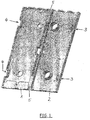
- Figure 1 shows the exemplary geometric design of two housing parts, 1, 2, wherein the invention is independent of the geometrical dimensions of the housing parts 1, 2 applicable.
- the electronic device which is umber of the two housing parts 1, 2, wherein it is the electronic device, for example, an antenna amplifier, a video module or the like for the transmission and reception of signals from a vehicle or to is inserted into the vehicle.
- the preferred field of application of the housing according to the invention is the vehicle technology, since rough ambient conditions such as temperature fluctuations, vibrations and the like prevail, so that it is of particular importance in this preferred field of application that the two (or more than two) housing parts 1, 2 reliably and permanently together get connected.
- the snap part 3 according to the invention is present once or several times on a housing part, here in FIG.
- the snap part on the housing part 2 is a tab 31 with a recess 32, wherein the tab 31 is angled in this embodiment.
- This bend is realized by slots 33 which protrude into the surface of the housing part 2, so that the tab 31 is longitudinally separated by slots 33 from the housing part 2 and connected to the housing part 2 with only one end portion.
- Such a tab 31 is thus arranged movably on the housing part 2, including on End of a slot 33 still a widening 34 may be present to prevent tearing of the tab 31 during its movement.
- a corresponding snap part 4 on the housing part 1 is provided with the snap part on the housing part 2.
- the two snap parts 3, 4 form the snap connection, so that the snap part can be brought into operative connection with the snap part 4.
- the snap part 4 is arranged in a recessed relative to the surface of the housing part 1 region 41 in a particularly advantageous manner, wherein in this recessed portion 41, a latching hook 42 is arranged, which can be brought into operative connection with the recess 32 of the angled tab 31.
- the housing parts 1, 2 shown in Figure 1 are either separately or together produced, then in a particularly advantageous manner during the manufacture of the two housing parts 1, 2 therebetween a film hinge 5 (general-connection means) are present.
- the film hinge 5 has the advantage that the two housing parts 1, 2 only with the electronic device (in particular circuit board with electronic components and connectors and contact points) folded together and must be connected to each other via the two snap parts 3, 4. This can be done very easily and very quickly manually or automatically. It is also conceivable that, for example, along the longitudinal edge of the two housing parts 1 and 2, a seal is provided.
- guide elements such as pins and corresponding holes or the like
- Such guide elements are required in particular when the two housing parts 1, 2 are not connected to each other via connecting means (such as the film hinge 5).
- the at least two housing parts 1, 2 are produced in a plastic injection molding process, which allows it by a corresponding shape, to realize all structural configurations of the two housing parts 1, 2 in a manufacturing process. This applies in particular to the snap parts 3, 4 which are already present after the two housing parts 1, 2 have been produced. In a particularly advantageous manner, this eliminates post-processing.
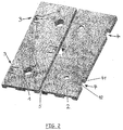
- Figure 2 shows in addition the top view of the two housing parts 1, 2, wherein in a particularly advantageous manner, the mutually corresponding position of the snap parts 3, 4 can be seen.
- the snap part 3, for example, on the housing part 2 may, but need not, be arranged in a recessed area 41.
- a latching hook 42 is present, which can be brought into operative connection with the recess 32 of the angled tab 31. Due to the corresponding shape of the tab 31 and its arrangement within the housing part 1, in particular due to the slots 33, this is deflected from the plane of the surface of the housing part 1.
- the geometric dimensions, in particular the position of the tab 31 to the latching hook 42 are designed so that when folding the two housing parts 1, 2 to the film hinge 5 (or other assembly) does not yet cause the latch 31 on the latching hook 42 ,
- This engagement is achieved in a particularly advantageous manner only by applying mechanical pressure to the tab 31, which in particular has a projection 35 for this purpose.
- the tab 31 is pressed over the latching hook 42 and can snap in (snap into place).
- this snap connection is constantly under tension and braces the two housing parts 1, 2 with each other.
- the projection 35 is provided, via which the tab 31 can be depressed by hand (eg thumb or forefinger) or with a tool, if necessary. Also automated.
- the bias which is effected with the snap connection according to the invention, in particular realized by the tab 31 and the latching hook 42.
Landscapes
- Engineering & Computer Science (AREA)
- Microelectronics & Electronic Packaging (AREA)
- Casings For Electric Apparatus (AREA)
- Injection Moulding Of Plastics Or The Like (AREA)
- Moulds For Moulding Plastics Or The Like (AREA)
- Input Circuits Of Receivers And Coupling Of Receivers And Audio Equipment (AREA)
- Details Of Aerials (AREA)
Claims (8)
- Boîtier, en particulier un boîtier pour un appareil électronique à utiliser en technique automobile, qui présente au moins deux parties de boîtier (1, 2) en matière plastique, sachant que les deux parties de boîtier (1, 2) peuvent être verrouillées entre elles au moyen d'au moins un assemblage à enclenchement, caractérisé en ce que l'assemblage à enclenchement au moins unique est conçu de telle sorte qu'il se trouve sous précontrainte à la suite du verrouillage, sachant qu'à cet effet, un élément d'enclenchement (3) pouvant céder élastiquement est disposé sur l'une (2) des parties de boîtier, et un élément d'enclenchement (4) est disposé sur l'autre partie de boîtier (1) au moins unique, élément qui peut être amené en liaison fonctionnelle avec l'élément d'enclenchement (3) en exerçant une force sur le boîtier dans la région de l'assemblage par enclenchement.
- Boîtier selon la revendication 1, caractérisé en ce que l'élément d'enclenchement (3) sur la partie de boîtier (2) est une patte (31) pourvue d'un évidement (32), et l'élément d'enclenchement (4), qui peut être amené en liaison fonctionnelle avec lui, sur la partie de boîtier (1) est un crochet de crantage (42).
- Boîtier selon la revendication 2, caractérisé en ce que la patte (31) est séparée de la partie de boîtier (2) par des fentes (33) et n'est reliée à la partie de boîtier (2) que par une région terminale.
- Boîtier selon la revendication 1 ou 2, caractérisé en ce que la patte (31) présente une saillie (35) dirigée vers l'extérieur.
- Boîtier selon la revendication 2, 3 ou 4, caractérisé en ce que le crochet de crantage (42) est disposé dans une région (41) en retrait par rapport à la surface de la partie de boîtier (1).
- Boîtier selon l'une quelconque des revendications précédentes, caractérisé en ce que les parties de boîtier (1,2), qui sont au moins au nombre de deux, sont séparées ou sont mutuellement assemblées par des moyens d'assemblage.
- Boîtier selon la revendication 6, caractérisé en ce que les moyens d'assemblage consistent en au moins une charnière pelliculaire (5).
- Boîtier selon l'une quelconque des revendications précédentes, caractérisé en ce que les parties de boîtier (1,2), qui sont au moins au nombre de deux, sont fabriquées par un procédé de moulage par injection de matière plastique.
Applications Claiming Priority (3)
| Application Number | Priority Date | Filing Date | Title |
|---|---|---|---|
| DE10247631 | 2002-10-11 | ||
| DE10247631 | 2002-10-11 | ||
| PCT/EP2003/011260 WO2004036970A1 (fr) | 2002-10-11 | 2003-10-10 | Boitier pour amplificateur d'antenne |
Publications (2)
| Publication Number | Publication Date |
|---|---|
| EP1550359A1 EP1550359A1 (fr) | 2005-07-06 |
| EP1550359B1 true EP1550359B1 (fr) | 2006-03-29 |
Family
ID=32102747
Family Applications (1)
| Application Number | Title | Priority Date | Filing Date |
|---|---|---|---|
| EP03756479A Expired - Lifetime EP1550359B1 (fr) | 2002-10-11 | 2003-10-10 | Boitier pour amplificateur d'antenne |
Country Status (6)
| Country | Link |
|---|---|
| US (1) | US7189919B2 (fr) |
| EP (1) | EP1550359B1 (fr) |
| JP (1) | JP4567455B2 (fr) |
| AT (1) | ATE322146T1 (fr) |
| DE (1) | DE50302830D1 (fr) |
| WO (1) | WO2004036970A1 (fr) |
Families Citing this family (2)
| Publication number | Priority date | Publication date | Assignee | Title |
|---|---|---|---|---|
| ES2330984B1 (es) * | 2007-03-29 | 2010-09-10 | M. Del Mar Guell Ferrer | Caja-estuche para cuadros de control de automatismos. |
| JP6057117B2 (ja) * | 2012-04-27 | 2017-01-11 | 株式会社ノーリツ | 壁面設置型のリモコン |
Family Cites Families (13)
| Publication number | Priority date | Publication date | Assignee | Title |
|---|---|---|---|---|
| FR2614169B1 (fr) | 1987-04-14 | 1996-01-05 | Mang Ets Gerard | Boitier pour petit appareil electrique |
| DE9017103U1 (de) * | 1990-12-19 | 1991-03-07 | Mannesmann Kienzle Gmbh, 78052 Villingen-Schwenningen | Anordnung zum Verbinden zweier Gehäuseteile eines Einbaugehäuses |
| US5373104A (en) * | 1993-07-12 | 1994-12-13 | Delco Electronics Corporation | Control module with integral fastening/locking assembly |
| US5536917A (en) * | 1994-06-23 | 1996-07-16 | Motorla, Inc. | Housing with integral thin film resistive snap-fits |
| JP3075118B2 (ja) * | 1994-12-29 | 2000-08-07 | 住友電装株式会社 | 電気接続箱 |
| US5684274A (en) * | 1995-12-04 | 1997-11-04 | Kmd Technologies, Inc. | Enclosure for cable splice assembly |
| JP3257469B2 (ja) * | 1997-09-24 | 2002-02-18 | 住友電装株式会社 | 電気接続箱 |
| US6126458A (en) * | 1999-07-13 | 2000-10-03 | Yazaki North America, Inc. | Bussed electrical center assembly with connector pre-set |
| US6444904B1 (en) * | 2000-04-20 | 2002-09-03 | Motorola, Inc. | Orthogonal assembly latch |
| DE10100376A1 (de) * | 2001-01-05 | 2002-07-11 | Valeo Schalter & Sensoren Gmbh | Ultraschallwandler für ein Kraftfahrzeug |
| US6570088B1 (en) * | 2002-03-13 | 2003-05-27 | Sumitomo Wiring Systems, Ltd. | Junction box assembly |
| US6848946B2 (en) * | 2002-07-30 | 2005-02-01 | Tyco Eletro-Eletronica Ltda. | Electrical fuse realy box, apparatus, method and article of manufacture |
| US6815612B2 (en) * | 2002-10-18 | 2004-11-09 | Corning Cable Systems Llc | Watertight seal for network interface device |
-
2003
- 2003-10-10 AT AT03756479T patent/ATE322146T1/de not_active IP Right Cessation
- 2003-10-10 EP EP03756479A patent/EP1550359B1/fr not_active Expired - Lifetime
- 2003-10-10 US US10/528,128 patent/US7189919B2/en not_active Expired - Lifetime
- 2003-10-10 WO PCT/EP2003/011260 patent/WO2004036970A1/fr not_active Ceased
- 2003-10-10 DE DE50302830T patent/DE50302830D1/de not_active Expired - Lifetime
- 2003-10-10 JP JP2004544146A patent/JP4567455B2/ja not_active Expired - Lifetime
Also Published As
| Publication number | Publication date |
|---|---|
| JP2006503429A (ja) | 2006-01-26 |
| ATE322146T1 (de) | 2006-04-15 |
| US7189919B2 (en) | 2007-03-13 |
| US20050247473A1 (en) | 2005-11-10 |
| EP1550359A1 (fr) | 2005-07-06 |
| WO2004036970A1 (fr) | 2004-04-29 |
| JP4567455B2 (ja) | 2010-10-20 |
| DE50302830D1 (de) | 2006-05-18 |
Similar Documents
| Publication | Publication Date | Title |
|---|---|---|
| DE3877292T2 (de) | Element mit elastischen, sich bei spannung versteifenden gelenken. | |
| DE69822393T2 (de) | Elektrischer Steckverbinder für flexible Flachband-Schaltkreise | |
| EP1494255B1 (fr) | Dispositif pour l'insertion et l'extraction d' un fusible | |
| DE102010017262B4 (de) | Anschlussstecker mit Verriegelungseinrichtung | |
| EP3552463B1 (fr) | Assemblage de cartes de circuits imprimés et son procédé de fabrication | |
| DE102016102071B3 (de) | Elektrische Steckverbinderanordnung und Löseelement hierzu | |
| DE112017007139B4 (de) | Gehäuse, elektronische Vorrichtung und Verfahren zur Herstellung eines Gehäuses | |
| DE602005002868T2 (de) | Kraftfahrzeugrahmenanordnung | |
| WO2015059027A1 (fr) | Boîtier de rail support | |
| DE602004006440T2 (de) | Einrichtung zum Verriegeln eines Verbindermoduls in einem Modulhalter | |
| EP2789219A2 (fr) | Module electronique | |
| DE19625228C2 (de) | Systemträger für die Montage einer integrierten Schaltung in einem Spritzgußgehäuse | |
| EP2183736B1 (fr) | Dispositif d'identification pour lignes électriques | |
| EP1771052B1 (fr) | Support pour composants électriques/électroniques en particulier dans une serrure de portière de véhicule automobile | |
| EP1550359B1 (fr) | Boitier pour amplificateur d'antenne | |
| EP0452555B1 (fr) | Connecteur, notamment connecteur hermaphrodite | |
| DE2712759A1 (de) | Schluesselkappe | |
| DE102012105352A1 (de) | Positionierelement | |
| DE112023001631T5 (de) | Vorrichtung zum schalten | |
| EP0469284B1 (fr) | Elément de montage | |
| DE10134958A1 (de) | Leiterplatine | |
| EP1777779A1 (fr) | Antenne fixée à la plaque extérieure d'une automobile comportant une fixation centrale d'un couvercle externe à un couvercle interne de l'antenne | |
| EP1494517B1 (fr) | Boítier pour recevoir un circuit imprimé | |
| DE102016200568B4 (de) | Mehrteiliges Gehäuse aus Kunststoff | |
| EP3937599B1 (fr) | Logement et procédé de montage d'un logement |
Legal Events
| Date | Code | Title | Description |
|---|---|---|---|
| PUAI | Public reference made under article 153(3) epc to a published international application that has entered the european phase |
Free format text: ORIGINAL CODE: 0009012 |
|
| 17P | Request for examination filed |
Effective date: 20040930 |
|
| AK | Designated contracting states |
Kind code of ref document: A1 Designated state(s): AT BE BG CH CY CZ DE DK EE ES FI FR GB GR HU IE IT LI LU MC NL PT RO SE SI SK TR |
|
| RIN1 | Information on inventor provided before grant (corrected) |
Inventor name: SILVA, DAVID |
|
| GRAP | Despatch of communication of intention to grant a patent |
Free format text: ORIGINAL CODE: EPIDOSNIGR1 |
|
| GRAS | Grant fee paid |
Free format text: ORIGINAL CODE: EPIDOSNIGR3 |
|
| GRAA | (expected) grant |
Free format text: ORIGINAL CODE: 0009210 |
|
| AK | Designated contracting states |
Kind code of ref document: B1 Designated state(s): AT BE BG CH CY CZ DE DK EE ES FI FR GB GR HU IE IT LI LU MC NL PT RO SE SI SK TR |
|
| PG25 | Lapsed in a contracting state [announced via postgrant information from national office to epo] |
Ref country code: IT Free format text: LAPSE BECAUSE OF FAILURE TO SUBMIT A TRANSLATION OF THE DESCRIPTION OR TO PAY THE FEE WITHIN THE PRESCRIBED TIME-LIMIT;WARNING: LAPSES OF ITALIAN PATENTS WITH EFFECTIVE DATE BEFORE 2007 MAY HAVE OCCURRED AT ANY TIME BEFORE 2007. THE CORRECT EFFECTIVE DATE MAY BE DIFFERENT FROM THE ONE RECORDED. Effective date: 20060329 Ref country code: RO Free format text: LAPSE BECAUSE OF FAILURE TO SUBMIT A TRANSLATION OF THE DESCRIPTION OR TO PAY THE FEE WITHIN THE PRESCRIBED TIME-LIMIT Effective date: 20060329 Ref country code: NL Free format text: LAPSE BECAUSE OF FAILURE TO SUBMIT A TRANSLATION OF THE DESCRIPTION OR TO PAY THE FEE WITHIN THE PRESCRIBED TIME-LIMIT Effective date: 20060329 Ref country code: SK Free format text: LAPSE BECAUSE OF FAILURE TO SUBMIT A TRANSLATION OF THE DESCRIPTION OR TO PAY THE FEE WITHIN THE PRESCRIBED TIME-LIMIT Effective date: 20060329 Ref country code: IE Free format text: LAPSE BECAUSE OF FAILURE TO SUBMIT A TRANSLATION OF THE DESCRIPTION OR TO PAY THE FEE WITHIN THE PRESCRIBED TIME-LIMIT Effective date: 20060329 Ref country code: SI Free format text: LAPSE BECAUSE OF FAILURE TO SUBMIT A TRANSLATION OF THE DESCRIPTION OR TO PAY THE FEE WITHIN THE PRESCRIBED TIME-LIMIT Effective date: 20060329 |
|
| REG | Reference to a national code |
Ref country code: GB Ref legal event code: FG4D Free format text: NOT ENGLISH |
|
| REG | Reference to a national code |
Ref country code: CH Ref legal event code: EP |
|
| REG | Reference to a national code |
Ref country code: IE Ref legal event code: FG4D Free format text: LANGUAGE OF EP DOCUMENT: GERMAN |
|
| REF | Corresponds to: |
Ref document number: 50302830 Country of ref document: DE Date of ref document: 20060518 Kind code of ref document: P |
|
| GBT | Gb: translation of ep patent filed (gb section 77(6)(a)/1977) |
Effective date: 20060502 |
|
| PG25 | Lapsed in a contracting state [announced via postgrant information from national office to epo] |
Ref country code: DK Free format text: LAPSE BECAUSE OF FAILURE TO SUBMIT A TRANSLATION OF THE DESCRIPTION OR TO PAY THE FEE WITHIN THE PRESCRIBED TIME-LIMIT Effective date: 20060629 Ref country code: SE Free format text: LAPSE BECAUSE OF FAILURE TO SUBMIT A TRANSLATION OF THE DESCRIPTION OR TO PAY THE FEE WITHIN THE PRESCRIBED TIME-LIMIT Effective date: 20060629 Ref country code: BG Free format text: LAPSE BECAUSE OF FAILURE TO SUBMIT A TRANSLATION OF THE DESCRIPTION OR TO PAY THE FEE WITHIN THE PRESCRIBED TIME-LIMIT Effective date: 20060629 |
|
| PG25 | Lapsed in a contracting state [announced via postgrant information from national office to epo] |
Ref country code: ES Free format text: LAPSE BECAUSE OF FAILURE TO SUBMIT A TRANSLATION OF THE DESCRIPTION OR TO PAY THE FEE WITHIN THE PRESCRIBED TIME-LIMIT Effective date: 20060710 |
|
| PG25 | Lapsed in a contracting state [announced via postgrant information from national office to epo] |
Ref country code: PT Free format text: LAPSE BECAUSE OF FAILURE TO SUBMIT A TRANSLATION OF THE DESCRIPTION OR TO PAY THE FEE WITHIN THE PRESCRIBED TIME-LIMIT Effective date: 20060829 |
|
| ET | Fr: translation filed | ||
| NLV1 | Nl: lapsed or annulled due to failure to fulfill the requirements of art. 29p and 29m of the patents act | ||
| PG25 | Lapsed in a contracting state [announced via postgrant information from national office to epo] |
Ref country code: MC Free format text: LAPSE BECAUSE OF NON-PAYMENT OF DUE FEES Effective date: 20061031 |
|
| REG | Reference to a national code |
Ref country code: IE Ref legal event code: FD4D |
|
| PLBE | No opposition filed within time limit |
Free format text: ORIGINAL CODE: 0009261 |
|
| STAA | Information on the status of an ep patent application or granted ep patent |
Free format text: STATUS: NO OPPOSITION FILED WITHIN TIME LIMIT |
|
| 26N | No opposition filed |
Effective date: 20070102 |
|
| BERE | Be: lapsed |
Owner name: HIRSCHMANN ELECTRONICS G.M.B.H. & CO. KG Effective date: 20061031 |
|
| PG25 | Lapsed in a contracting state [announced via postgrant information from national office to epo] |
Ref country code: AT Free format text: LAPSE BECAUSE OF NON-PAYMENT OF DUE FEES Effective date: 20061010 |
|
| PG25 | Lapsed in a contracting state [announced via postgrant information from national office to epo] |
Ref country code: GR Free format text: LAPSE BECAUSE OF FAILURE TO SUBMIT A TRANSLATION OF THE DESCRIPTION OR TO PAY THE FEE WITHIN THE PRESCRIBED TIME-LIMIT Effective date: 20060630 Ref country code: CZ Free format text: LAPSE BECAUSE OF FAILURE TO SUBMIT A TRANSLATION OF THE DESCRIPTION OR TO PAY THE FEE WITHIN THE PRESCRIBED TIME-LIMIT Effective date: 20060329 |
|
| REG | Reference to a national code |
Ref country code: CH Ref legal event code: PL |
|
| PG25 | Lapsed in a contracting state [announced via postgrant information from national office to epo] |
Ref country code: FI Free format text: LAPSE BECAUSE OF FAILURE TO SUBMIT A TRANSLATION OF THE DESCRIPTION OR TO PAY THE FEE WITHIN THE PRESCRIBED TIME-LIMIT Effective date: 20060329 Ref country code: EE Free format text: LAPSE BECAUSE OF FAILURE TO SUBMIT A TRANSLATION OF THE DESCRIPTION OR TO PAY THE FEE WITHIN THE PRESCRIBED TIME-LIMIT Effective date: 20060329 |
|
| PG25 | Lapsed in a contracting state [announced via postgrant information from national office to epo] |
Ref country code: CH Free format text: LAPSE BECAUSE OF NON-PAYMENT OF DUE FEES Effective date: 20071031 Ref country code: TR Free format text: LAPSE BECAUSE OF FAILURE TO SUBMIT A TRANSLATION OF THE DESCRIPTION OR TO PAY THE FEE WITHIN THE PRESCRIBED TIME-LIMIT Effective date: 20060329 Ref country code: HU Free format text: LAPSE BECAUSE OF FAILURE TO SUBMIT A TRANSLATION OF THE DESCRIPTION OR TO PAY THE FEE WITHIN THE PRESCRIBED TIME-LIMIT Effective date: 20060930 Ref country code: LI Free format text: LAPSE BECAUSE OF NON-PAYMENT OF DUE FEES Effective date: 20071031 Ref country code: LU Free format text: LAPSE BECAUSE OF NON-PAYMENT OF DUE FEES Effective date: 20061010 |
|
| PG25 | Lapsed in a contracting state [announced via postgrant information from national office to epo] |
Ref country code: CY Free format text: LAPSE BECAUSE OF FAILURE TO SUBMIT A TRANSLATION OF THE DESCRIPTION OR TO PAY THE FEE WITHIN THE PRESCRIBED TIME-LIMIT Effective date: 20060329 |
|
| PG25 | Lapsed in a contracting state [announced via postgrant information from national office to epo] |
Ref country code: BE Free format text: LAPSE BECAUSE OF FAILURE TO SUBMIT A TRANSLATION OF THE DESCRIPTION OR TO PAY THE FEE WITHIN THE PRESCRIBED TIME-LIMIT Effective date: 20061031 |
|
| REG | Reference to a national code |
Ref country code: DE Ref legal event code: R081 Ref document number: 50302830 Country of ref document: DE Owner name: HIRSCHMANN CAR COMMUNICATION GMBH, DE Free format text: FORMER OWNER: HIRSCHMANN ELECTRONICS GMBH & CO. KG, 72654 NECKARTENZLINGEN, DE Effective date: 20120306 |
|
| REG | Reference to a national code |
Ref country code: GB Ref legal event code: 732E Free format text: REGISTERED BETWEEN 20120809 AND 20120815 |
|
| REG | Reference to a national code |
Ref country code: FR Ref legal event code: TP Owner name: HIRSCHMANN CAR COMMUNICATION GMBH, DE Effective date: 20120803 Ref country code: FR Ref legal event code: CJ Effective date: 20120803 Ref country code: FR Ref legal event code: CD Owner name: HIRSCHMANN CAR COMMUNICATION GMBH, DE Effective date: 20120803 |
|
| REG | Reference to a national code |
Ref country code: FR Ref legal event code: PLFP Year of fee payment: 13 |
|
| REG | Reference to a national code |
Ref country code: FR Ref legal event code: PLFP Year of fee payment: 14 |
|
| REG | Reference to a national code |
Ref country code: FR Ref legal event code: PLFP Year of fee payment: 15 |
|
| REG | Reference to a national code |
Ref country code: FR Ref legal event code: PLFP Year of fee payment: 16 |
|
| REG | Reference to a national code |
Ref country code: DE Ref legal event code: R082 Ref document number: 50302830 Country of ref document: DE Representative=s name: WILHELM & BECK, DE |
|
| GBPC | Gb: european patent ceased through non-payment of renewal fee |
Effective date: 20191010 |
|
| PG25 | Lapsed in a contracting state [announced via postgrant information from national office to epo] |
Ref country code: GB Free format text: LAPSE BECAUSE OF NON-PAYMENT OF DUE FEES Effective date: 20191010 |
|
| PGFP | Annual fee paid to national office [announced via postgrant information from national office to epo] |
Ref country code: FR Payment date: 20220908 Year of fee payment: 20 |
|
| PGFP | Annual fee paid to national office [announced via postgrant information from national office to epo] |
Ref country code: DE Payment date: 20220831 Year of fee payment: 20 |
|
| REG | Reference to a national code |
Ref country code: DE Ref legal event code: R071 Ref document number: 50302830 Country of ref document: DE |