EP1550189B1 - Frame - Google Patents
Frame Download PDFInfo
- Publication number
- EP1550189B1 EP1550189B1 EP03748857.4A EP03748857A EP1550189B1 EP 1550189 B1 EP1550189 B1 EP 1550189B1 EP 03748857 A EP03748857 A EP 03748857A EP 1550189 B1 EP1550189 B1 EP 1550189B1
- Authority
- EP
- European Patent Office
- Prior art keywords
- frame
- modules
- rails
- side rails
- openings
- Prior art date
- Legal status (The legal status is an assumption and is not a legal conclusion. Google has not performed a legal analysis and makes no representation as to the accuracy of the status listed.)
- Expired - Lifetime
Links
- 230000006835 compression Effects 0.000 claims description 26
- 238000007906 compression Methods 0.000 claims description 26
- 238000007789 sealing Methods 0.000 claims description 11
- 230000035515 penetration Effects 0.000 claims description 8
- 239000000463 material Substances 0.000 claims description 4
- 230000004224 protection Effects 0.000 description 7
- 230000014509 gene expression Effects 0.000 description 4
- 239000012530 fluid Substances 0.000 description 3
- 239000007789 gas Substances 0.000 description 3
- 238000004519 manufacturing process Methods 0.000 description 3
- 239000000428 dust Substances 0.000 description 2
- 238000005192 partition Methods 0.000 description 2
- FGRBYDKOBBBPOI-UHFFFAOYSA-N 10,10-dioxo-2-[4-(N-phenylanilino)phenyl]thioxanthen-9-one Chemical compound O=C1c2ccccc2S(=O)(=O)c2ccc(cc12)-c1ccc(cc1)N(c1ccccc1)c1ccccc1 FGRBYDKOBBBPOI-UHFFFAOYSA-N 0.000 description 1
- 241000256602 Isoptera Species 0.000 description 1
- 241000283984 Rodentia Species 0.000 description 1
- 239000000853 adhesive Substances 0.000 description 1
- 230000001070 adhesive effect Effects 0.000 description 1
- 230000009286 beneficial effect Effects 0.000 description 1
- 238000004891 communication Methods 0.000 description 1
- 238000010276 construction Methods 0.000 description 1
- 238000010411 cooking Methods 0.000 description 1
- 238000005520 cutting process Methods 0.000 description 1
- 238000009826 distribution Methods 0.000 description 1
- 230000005611 electricity Effects 0.000 description 1
- 238000005304 joining Methods 0.000 description 1
- 239000007788 liquid Substances 0.000 description 1
- 239000007769 metal material Substances 0.000 description 1
- 238000012856 packing Methods 0.000 description 1
- 238000010248 power generation Methods 0.000 description 1
- 238000003860 storage Methods 0.000 description 1
- XLYOFNOQVPJJNP-UHFFFAOYSA-N water Substances O XLYOFNOQVPJJNP-UHFFFAOYSA-N 0.000 description 1
Images


Classifications
-
- F—MECHANICAL ENGINEERING; LIGHTING; HEATING; WEAPONS; BLASTING
- F16—ENGINEERING ELEMENTS AND UNITS; GENERAL MEASURES FOR PRODUCING AND MAINTAINING EFFECTIVE FUNCTIONING OF MACHINES OR INSTALLATIONS; THERMAL INSULATION IN GENERAL
- F16L—PIPES; JOINTS OR FITTINGS FOR PIPES; SUPPORTS FOR PIPES, CABLES OR PROTECTIVE TUBING; MEANS FOR THERMAL INSULATION IN GENERAL
- F16L5/00—Devices for use where pipes, cables or protective tubing pass through walls or partitions
- F16L5/02—Sealing
-
- H—ELECTRICITY
- H02—GENERATION; CONVERSION OR DISTRIBUTION OF ELECTRIC POWER
- H02G—INSTALLATION OF ELECTRIC CABLES OR LINES, OR OF COMBINED OPTICAL AND ELECTRIC CABLES OR LINES
- H02G3/00—Installations of electric cables or lines or protective tubing therefor in or on buildings, equivalent structures or vehicles
- H02G3/22—Installations of cables or lines through walls, floors or ceilings, e.g. into buildings
-
- F—MECHANICAL ENGINEERING; LIGHTING; HEATING; WEAPONS; BLASTING
- F16—ENGINEERING ELEMENTS AND UNITS; GENERAL MEASURES FOR PRODUCING AND MAINTAINING EFFECTIVE FUNCTIONING OF MACHINES OR INSTALLATIONS; THERMAL INSULATION IN GENERAL
- F16L—PIPES; JOINTS OR FITTINGS FOR PIPES; SUPPORTS FOR PIPES, CABLES OR PROTECTIVE TUBING; MEANS FOR THERMAL INSULATION IN GENERAL
- F16L5/00—Devices for use where pipes, cables or protective tubing pass through walls or partitions
Definitions
- the present invention concerns a frame of modular form for cable entries, pipe penetrations or the like.
- the frames are parts of systems used to seal at cable entries, pipe penetrations etc.
- the systems comprise further elements or units to be placed tightly surrounding the cables, compression units etc.
- Systems of this kind are used in many different environments, such as for cabinets, technical shelters, junction boxes and machines. They are used in different industrial environments, such as automotive, telecom, power generation and distribution, as well as marine and offshore.
- Systems of this kind or rather the frames to receive different parts are often pre-mounted in different parts, such as building components, walls, roofs etc., containers or the like. Further parts of the systems together with the cables, pipes or the like are normally mounted once the building parts or containers are in their final locations.
- Containers are often used to hold different kinds of specialised equipment, which containers may be relatively flexible and are transported in an assembled state to a final destination.
- the systems may have to seal against fluid, gas, fire, rodents, termites, dust, moisture etc., and may receive cables for electricity, communication, computers etc. or pipes for different gases or liquids such as water, compressed air, hydraulic fluid and cooking gas.
- WO89/07851 discloses a frame according to the preamble of claim 1.
- a general object of the present invention is that the costs of the frame should be kept as low as possible without jeopardising the function. It is costs both in manufacture and in handling that should be kept low. To simplify handling the different frame parts should be easy to assemble both to each other and to constructions where they are to be placed. A further means to simplify handling is to reduce the number of parts needed to form frames of different sizes. This means that there will be a reduced demand on parts for manufacture and storage.
- the frame include some kind of transport protection, covering the openings of the frame to receive the cables, pipes or the like. By covering the openings dust, fluid, moisture etc. is hindered from entering a container or the like during transport or before the actual mounting of cables, pipes or the like.
- the frames are normally to be used in many different locations and for many different cables, pipes or the like, and, thus, there is a need for a frame that in a relatively simple way can be adapted to the needs of each specific case.
- a frame for cable entries, pipe penetrations or the like is formed.
- the frame comprises at least two end modules forming at least one opening to receive the cable entries, pipe penetrations or the like. Furthermore, it has means to cover the openings of the frame before receiving the cables, pipes or the like.
- the frame of the present invention is furnished with a flange to facilitate mounting.
- the transport protection may also be used to make the frame adaptable to future use.
- the frame should be relatively easy to adapt to different uses, possibly with retrofit.
- the systems using frames of the present invention are developed to involve some kind of compression unit.
- the compression units will exert pressure outwardly on the frame.
- the frame must be able to withstand pressures formed when the compression unit or units is in use.
- the frame is preferably made of a plastic material.
- An example of an end part or module 1 and an intermediate part or module 2 used to form a frame receiving separate units for cable entries, pipe penetrations or the like is shown in the enclosed figures.
- the frame normally also receives one or more compression units.
- To form the frame at least two end modules 1 are needed.
- one or more intermediate modules 2 may be placed between the end modules 1. As indicated above, no intermediate module 2 is needed if the size of two assembled end modules 1 suffice.
- the expression “height” refers to the distance between the inner parts of the side rails 6, 9 of each respective frame module 1, 2. The height is referred to as h in Fig. 4 .
- the expression “width” according to the present invention refers to the distance between the inner parts of the end rails 5 of an assembled frame. The width is referred to as w in Fig. 4 .
- the end module 1 has a rail formed of one end rail 5 and two side rails 6. On the outside of said rails 5, 6 a flange 3 is formed. In the flange 3 a number of holes 4 are formed. Said holes 4 are to receive fastening means for fixing the frame to a wall, floor, roof, top, bottom or the like of a house, ship, cabinet, container or the like. In other embodiments the flange 3 has no pre-formed holes. In stead holes are made depending on the actual needs in each specific case or the frame is mounted by means of an adhesive or the like. Depending on the actual placing of the frame different types of fastening means may be used, as understood by a person skilled in the art. As the fastening means as such is of no importance for the present invention it will not be discussed further here.
- each side rail 6 a groove 8 is arranged, which is to be used when the frame is assembled, as discussed further below.
- a peg 10 and an opening 11 are arranged on the free ends of the side rails 6 .
- the peg 10 is arranged on one of the side rails 6, while the opening is arranged on the other side rail 6.
- the peg 10 and the opening 11 are to co-operate with corresponding pegs 10 and openings 11 on adjacent parts when the frame is assembled. Said pegs 10 and openings 11 assist in keeping the different parts in a desired, correct position.
- the centre part 16 has the function of transport protection if the frame is pre-mounted in a building part, container etc. Said centre part 16 is to be removed just before cables, pipes or the like are to be received.
- a compression unit is shown by way of an example in Figs. 7 and 8 .
- Said compression unit is made in a simple way to keep the costs and number of parts at a minimum, as this is an essential part of the present invention.
- a person skilled in the art realises that other types of compression units may be used together with the frame of the present invention.
- the compression unit of the embodiment of Figs. 7 and 8 are based on a compression plate 21 placed under tension between the frame 24 and the separate units 28 in the form of cable entries, pipe penetrations etc. in use.
- the compression plate 21 has protrusions 22 at the ends to be received in grooves 25, 26 of the frame 24.
- the grooves have a introduction part 25 and a rounded part 26, to enable the compression plate 21 to be turned once it is in place in the frame 24.
- the compression plate 21 is turned by means of a tool 27 inserted in an opening 23 of the compression plate 21.
- Fig. 8 the steps of mounting the compression plate are schematically shown.
- the compression plate 21 When the compression plate 21 is mounted it will compress the separate units 28 in that the plate 21 presses on a partition 29. Partitions 29 are also inserted between the separate units 28.
- a cover 30 is often placed on the compression plate 21 after mounting, whereby a knurl 31 of the cover 30 is received in the opening 23 of the compression plate 21.
- a person skilled in the art realises that at least one compression unit is received in each opening of the frame surrounded by end, side and/or intermediate rails 5, 6, 9, 12.
- the numbers of openings and compression units are decided by the number of modules 1, 2 used.
- FIG. 2 an example of an intermediate module 2 is shown.
- One or more intermediate modules 2 are to be mounted between two end modules 1 to form a frame having two or more openings.
- the intermediate module 2 has two side rails 9. The position for these side rails 9 are to match the position of the side rails 6 of the end modules 1 and also side rails 9 of any further intermediate modules 2. Between and perpendicular to the side rails 9 an intermediate rail 12 is furnished. Outside the side rails 9 the intermediate module 2 has a flange 15. Also the flange 15 of the intermediate module 2 is furnished with holes 4 to receive suitable fastening means. A person skilled in the art realises that the number and positions of the holes 4 may vary. In other embodiments there may be no holes at manufacture. Any holes needed is then formed at mounting of the frame or the frame may be attached in a way not requiring any holes.
- the intermediate module 2 is furnished with a centre part 17 between the side rails 9, functioning as a possible transport protection. Said centre part 17 is to be removed when one or more cables, pipes or the like are to be received. To facilitate the removal of the centre part 17, indications of rupture are normally formed. This also applies for the centre part 16 of the end module 1.
- each side rail 9 a groove 13 is arranged, which is to be used when the frame is assembled, as discussed further below.
- a peg 10 and an opening 11 are arranged on the free ends of the side rails 9 .
- the peg 10 is arranged on one of the side rails 9, while the opening 11 is arranged on the other side rail 9.
- the peg 10 and the opening 11 are to co-operate with corresponding pegs 10 and openings 11 on adjacent parts when the frame is assembled. Said pegs 10 and openings 11 assist in keeping the different parts in a desired, correct position.
- the frame In use the frame is normally first assembled by the appropriate number of end and intermediate modules 1, 2. To assemble the frame at least two end modules 1 and possible intermediate module(s) are locked to each other by means of locking clamps 7.
- the locking clamps 7 are received in the grooves 8, 13 of the side rails 6, 9 of adjacent modules 1, 2.
- the form of the locking clamps 7 and the grooves 8, 13 are adapted to each other.
- the grooves 8, 13 of the side rails 6, 9 has a lip 14 extending along one side of the groove 8, 13 and covering a part of the opening of the groove 8, 13, as shown in Fig. 5 .
- the locking clamp 7 has a corresponding design with a base part 18, two side parts 19 at the ends of and at right angles to the base part 18 and two lips 19 at the ends of and at right angles to the side parts 19.
- the base part 18 and the lips 20 of the locking clamp 7 are parallel in the shown embodiment.
- the lips 20 of the locking clamp 7 are to grip behind the lips 14 of the grooves 8, 13.
- a sealing in form of a sealing tape, a O-ring, packing, gasket etc., is placed between the module parts that abut each other after assembly.
- at least one of the surfaces of the modules that are in contact with each other has a recess or the like.
- Fig. 9 One example of how the sealing part is received is indicated in Fig. 9 .
- one side rail 9 of an intermediate module 2 is shown enlarged.
- the side rail 9 has an end surface 32 for contact with an adjacent module and also the part of the module under the side rail 9 has an end surface 33 for contact with an adjacent module.
- the lower end surface 33 is placed somewhat inwardly of the end surface 32 of the side rail 9.
- the frame When the frame has been assembled it is fixed to a wall, top, bottom, floor, roof etc. of a cabinet, house, ship or the like.
- the outer rail formed of the side rails 6, 9 and end rails 5 will normally be placed adjacent the sides of an appropriate opening formed in the wall etc.
- the frame is fixed to the wall etc. by means of suitable fastening means with or without using the holes 4 of the flange 3.
- Normally the centre parts 16, 17 are kept in place for as long time as possible as protection. This may be of an advantage if a cabinet or the like is to be shipped to a final location.
- centre parts 16, 17 are removed. Normally, the centre parts 16, 17 are possible to remove by a relatively gentle push or knock. As indicated above the centre parts 16, 17 may have indications of fracture along the rails, to facilitate that the centre parts 16, 17 are totally removed. However, in some instances where the protection is critical, the centre parts 16, 17 are more firmly attached to the modules 1, 2. In this latter case the centre parts 16, 17 are to be removed by using some kind of cutting tool.
- a frame is shown assembled of two end modules 1 and two intermediate modules 2.
- the centre parts are removed from the end module 1 and the intermediate module 2, respectively.
- said frame part may now receive pipes, cables or the like together with sealing units. Normally also a compression unit is received in order to seal against the pipe, cable or the like.
- the frame modules 1, 2 could be formed without flanges 3, 15 and/or without centre parts 16, 17.
- the frames as assembled and thus, also the separate frame modules may have other forms and dimensions than those indicated by the shown figures.
- the frames may have more round forms and they may have other ratios between height and width.
- the frame modules 1, 2 are formed by a plastic material but a person skilled in the art realises that the frame parts may be manufactured of any suitable material including metallic material.
Description
- The present invention concerns a frame of modular form for cable entries, pipe penetrations or the like.
- Different frames of this kind are widely used today. The frames are parts of systems used to seal at cable entries, pipe penetrations etc. In addition to the frame the systems comprise further elements or units to be placed tightly surrounding the cables, compression units etc. Systems of this kind are used in many different environments, such as for cabinets, technical shelters, junction boxes and machines. They are used in different industrial environments, such as automotive, telecom, power generation and distribution, as well as marine and offshore.
- Systems of this kind or rather the frames to receive different parts are often pre-mounted in different parts, such as building components, walls, roofs etc., containers or the like. Further parts of the systems together with the cables, pipes or the like are normally mounted once the building parts or containers are in their final locations. Containers are often used to hold different kinds of specialised equipment, which containers may be relatively flexible and are transported in an assembled state to a final destination.
- The systems may have to seal against fluid, gas, fire, rodents, termites, dust, moisture etc., and may receive cables for electricity, communication, computers etc. or pipes for different gases or liquids such as water, compressed air, hydraulic fluid and cooking gas.
-
WO89/07851 claim 1. - A general object of the present invention is that the costs of the frame should be kept as low as possible without jeopardising the function. It is costs both in manufacture and in handling that should be kept low. To simplify handling the different frame parts should be easy to assemble both to each other and to constructions where they are to be placed. A further means to simplify handling is to reduce the number of parts needed to form frames of different sizes. This means that there will be a reduced demand on parts for manufacture and storage.
- As the frames often are pre-mounted it is beneficial if the frame include some kind of transport protection, covering the openings of the frame to receive the cables, pipes or the like. By covering the openings dust, fluid, moisture etc. is hindered from entering a container or the like during transport or before the actual mounting of cables, pipes or the like.
- The frames are normally to be used in many different locations and for many different cables, pipes or the like, and, thus, there is a need for a frame that in a relatively simple way can be adapted to the needs of each specific case.
- According to the invention a frame for cable entries, pipe penetrations or the like is formed. The frame comprises at least two end modules forming at least one opening to receive the cable entries, pipe penetrations or the like. Furthermore, it has means to cover the openings of the frame before receiving the cables, pipes or the like.
- Furthermore the frame of the present invention is furnished with a flange to facilitate mounting.
- The transport protection may also be used to make the frame adaptable to future use. Thus, it is possible to mount a frame having a number of positions occupied by the transport protections and which are removed only if further cables, pipes or the like are to be received. Still a further object is that the frame should be relatively easy to adapt to different uses, possibly with retrofit.
- The systems using frames of the present invention are developed to involve some kind of compression unit. In use the compression units will exert pressure outwardly on the frame. Thus, the frame must be able to withstand pressures formed when the compression unit or units is in use.
- In order to have low weight the frame is preferably made of a plastic material.
- Other objects and advantages of the present invention will be obvious for a person skilled in the art from reading the detailed description below of preferred embodiments.
- The invention will be described more closely below by way of an example and with reference to the enclosed drawings. In the drawings:
-
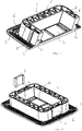
Fig. 1 is a perspective view of an end part of a modular frame according to the present invention, -
Fig. 2 is a perspective view of an intermediate part of a modular frame according to the present invention, -
Fig. 3 is a perspective view of a frame formed by two end modules, illustrating the principle for joining the modules, -
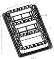
Fig. 4 is a perspective view of a frame formed of end modules and intermediate modules ofFigs. 1 and2 , respectively, -
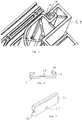
Fig. 5 is an enlarged view of a part of a module according to the present invention, -
Fig. 6 is a plan view of a locking clamp used in the present invention, -
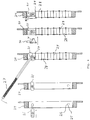
Fig. 7 is a perspective view of a compression plate that might be used in a frame according to the present invention, -
Fig. 8 is a schematic view illustrating mounting of the compression plate ofFig. 7 , and -
Fig. 9 is an enlarged view of a part of an module according to the present invention. - When the expressions "vertical", "horizontal", "outer", "inner" and other similar expressions are used in the description below, they refer to the directions as shown in the enclosed figures. A person skilled in the art realises that in use the frames may have any orientation, the orientation being directed by the actual use.
- An example of an end part or
module 1 and an intermediate part or module 2 used to form a frame receiving separate units for cable entries, pipe penetrations or the like is shown in the enclosed figures. The frame normally also receives one or more compression units. To form the frame at least twoend modules 1 are needed. Depending on the desired width of the frame one or more intermediate modules 2 may be placed between theend modules 1. As indicated above, no intermediate module 2 is needed if the size of two assembledend modules 1 suffice. A person skilled in the art realises that the design of the modules may vary. - In this description the expression "height" refers to the distance between the inner parts of the
side rails respective frame module 1, 2. The height is referred to as h inFig. 4 . The expression "width" according to the present invention refers to the distance between the inner parts of the end rails 5 of an assembled frame. The width is referred to as w inFig. 4 . - The
end module 1 has a rail formed of one end rail 5 and twoside rails 6. On the outside of said rails 5, 6 aflange 3 is formed. In the flange 3 a number of holes 4 are formed. Said holes 4 are to receive fastening means for fixing the frame to a wall, floor, roof, top, bottom or the like of a house, ship, cabinet, container or the like. In other embodiments theflange 3 has no pre-formed holes. In stead holes are made depending on the actual needs in each specific case or the frame is mounted by means of an adhesive or the like. Depending on the actual placing of the frame different types of fastening means may be used, as understood by a person skilled in the art. As the fastening means as such is of no importance for the present invention it will not be discussed further here. - In each side rail 6 a
groove 8 is arranged, which is to be used when the frame is assembled, as discussed further below. On the free ends of the side rails 6 apeg 10 and an opening 11 are arranged. Thepeg 10 is arranged on one of the side rails 6, while the opening is arranged on theother side rail 6. Thepeg 10 and the opening 11 are to co-operate withcorresponding pegs 10 and openings 11 on adjacent parts when the frame is assembled. Said pegs 10 and openings 11 assist in keeping the different parts in a desired, correct position. - Inside the
rail 5, 6 the frame has acentre part 16. Thecentre part 16 has the function of transport protection if the frame is pre-mounted in a building part, container etc.Said centre part 16 is to be removed just before cables, pipes or the like are to be received. - Inside the
rails 5, 6 of the frame sealing and compression units are to be received as is known by persons skilled in the art. These units are to seal against the cables, pipes or the like received in the frame. As the exact form and function of these units form no part of the present invention they will not be discussed further here. - However, an example of a compression unit is shown by way of an example in
Figs. 7 and8 . Said compression unit is made in a simple way to keep the costs and number of parts at a minimum, as this is an essential part of the present invention. A person skilled in the art realises that other types of compression units may be used together with the frame of the present invention. The compression unit of the embodiment ofFigs. 7 and8 are based on acompression plate 21 placed under tension between theframe 24 and theseparate units 28 in the form of cable entries, pipe penetrations etc. in use. Thecompression plate 21 hasprotrusions 22 at the ends to be received ingrooves frame 24. The grooves have aintroduction part 25 and arounded part 26, to enable thecompression plate 21 to be turned once it is in place in theframe 24. Thecompression plate 21 is turned by means of atool 27 inserted in anopening 23 of thecompression plate 21. InFig. 8 the steps of mounting the compression plate are schematically shown. When thecompression plate 21 is mounted it will compress theseparate units 28 in that theplate 21 presses on apartition 29.Partitions 29 are also inserted between theseparate units 28. Acover 30 is often placed on thecompression plate 21 after mounting, whereby aknurl 31 of thecover 30 is received in theopening 23 of thecompression plate 21. A person skilled in the art realises that at least one compression unit is received in each opening of the frame surrounded by end, side and/orintermediate rails modules 1, 2 used. - In
Fig. 2 an example of an intermediate module 2 is shown. One or more intermediate modules 2 are to be mounted between twoend modules 1 to form a frame having two or more openings. - The intermediate module 2 has two side rails 9. The position for these
side rails 9 are to match the position of the side rails 6 of theend modules 1 and alsoside rails 9 of any further intermediate modules 2. Between and perpendicular to the side rails 9 anintermediate rail 12 is furnished. Outside the side rails 9 the intermediate module 2 has aflange 15. Also theflange 15 of the intermediate module 2 is furnished with holes 4 to receive suitable fastening means. A person skilled in the art realises that the number and positions of the holes 4 may vary. In other embodiments there may be no holes at manufacture. Any holes needed is then formed at mounting of the frame or the frame may be attached in a way not requiring any holes. - Also the intermediate module 2 is furnished with a
centre part 17 between the side rails 9, functioning as a possible transport protection.Said centre part 17 is to be removed when one or more cables, pipes or the like are to be received. To facilitate the removal of thecentre part 17, indications of rupture are normally formed. This also applies for thecentre part 16 of theend module 1. - In each side rail 9 a
groove 13 is arranged, which is to be used when the frame is assembled, as discussed further below. On the free ends of the side rails 9 apeg 10 and an opening 11 are arranged. Thepeg 10 is arranged on one of the side rails 9, while the opening 11 is arranged on theother side rail 9. Thepeg 10 and the opening 11 are to co-operate withcorresponding pegs 10 and openings 11 on adjacent parts when the frame is assembled. Said pegs 10 and openings 11 assist in keeping the different parts in a desired, correct position. - In use the frame is normally first assembled by the appropriate number of end and
intermediate modules 1, 2. To assemble the frame at least twoend modules 1 and possible intermediate module(s) are locked to each other by means of locking clamps 7. The locking clamps 7 are received in thegrooves adjacent modules 1, 2. The form of the locking clamps 7 and thegrooves grooves lip 14 extending along one side of thegroove groove Fig. 5 . The locking clamp 7 has a corresponding design with abase part 18, twoside parts 19 at the ends of and at right angles to thebase part 18 and twolips 19 at the ends of and at right angles to theside parts 19. Thebase part 18 and thelips 20 of the locking clamp 7 are parallel in the shown embodiment. Thelips 20 of the locking clamp 7 are to grip behind thelips 14 of thegrooves pegs 10 and openings 11 of theadjacent modules 1, 2 assist in locking themodules 1, 2 to each other. Thus, themodules 1, 2 will be firmly locked to each other. A person skilled in the art realises that the exact form of the grooves and the locking clamps may vary as long as they are adapted to each other and give a secure and firm locking of theframe modules 1, 2. By the co-operation between the locking clamp 7 andgrooves - Normally a sealing, in form of a sealing tape, a O-ring, packing, gasket etc., is placed between the module parts that abut each other after assembly. To accommodate the sealing part at least one of the surfaces of the modules that are in contact with each other has a recess or the like. One example of how the sealing part is received is indicated in
Fig. 9 . In the example ofFig. 9 oneside rail 9 of an intermediate module 2 is shown enlarged. Theside rail 9 has anend surface 32 for contact with an adjacent module and also the part of the module under theside rail 9 has anend surface 33 for contact with an adjacent module. As indicated in the enlarged portion thelower end surface 33 is placed somewhat inwardly of theend surface 32 of theside rail 9. As the co-operating surfaces of the adjacent module are aligned there will be a small space formed under the side rails 9 when the frame is assembled. In said space a sealing tape or the like is to be received. The size of the space is adapted to the sealing element in such a way that the sealing element is under suitable pressure after assembly. - When the frame has been assembled it is fixed to a wall, top, bottom, floor, roof etc. of a cabinet, house, ship or the like. The outer rail formed of the side rails 6, 9 and end rails 5 will normally be placed adjacent the sides of an appropriate opening formed in the wall etc. The frame is fixed to the wall etc. by means of suitable fastening means with or without using the holes 4 of the
flange 3. Normally thecentre parts - Before the cable, pipe or the like is to be received, together with possible further sealing and compression units the
appropriate centre parts centre parts centre parts centre parts centre parts modules 1, 2. In this latter case thecentre parts - In
Fig. 4 , by way of an example, a frame is shown assembled of twoend modules 1 and two intermediate modules 2. In the lower part of the frame, as shown inFig. 3 the centre parts are removed from theend module 1 and the intermediate module 2, respectively. Thus, said frame part may now receive pipes, cables or the like together with sealing units. Normally also a compression unit is received in order to seal against the pipe, cable or the like. - A person skilled in the art realises that the different frame modules may be varied in many different ways. The
frame modules 1, 2 could be formed withoutflanges centre parts - Normally the
frame modules 1, 2 are formed by a plastic material but a person skilled in the art realises that the frame parts may be manufactured of any suitable material including metallic material.
Claims (12)
- A frame for cable entries, pipe penetrations or the like, characterized in that it comprises at least two end modules (1) forming at least one opening to receive the cable entries, pipe penetrations or the like and that it has means covering the openings of the frame before the cables, pipes or the like are received.
- The frame of claim 1, characterized in that the frame is to receive at least one compression unit in each opening and that each end module (1) has one end rail (5) and two side rails (6).
- The frame of claim 1 or 2, characterized in that one or more intermediate modules (2) are received between the end modules (1).
- The frame of claim 3, characterized in that each intermediate module (2) has two side rails (6) and one intermediate rail (12) and that the positions of the side rails (6) of the end modules (1) are in line with the positions of the side rails (6) of the intermediate module(s) (2) to form a common side rail when the modules (1, 2) are assembled to each other.
- The frame of claim 4, characterized in that the rails (5, 6, 9, 12) of the frame modules (1, 2) form rectangular openings when a number of modules (1, 2) are assembled to form the frame.
- The frame of claim 4 or 5, characterized in that the frame modules (1, 2) are formed with a flange (3, 15) outside the side and end rails (5, 6, 9), which flange (3, 15) is to receive fixation means.
- The frame of any of the claims 4 to 6, characterized in that the side rails (6, 9) are furnished with grooves (8, 13) to receive a locking means.
- The frame of claim 7, characterized in that the locking means is a locking clamp (7) to be received in grooves (8, 13) of side rails (6, 9) of adjacent frame modules (1, 2).
- The frame of any of the claims 4 to 8, characterized in that the free ends of the side rails (6, 9) are furnished with alternating pegs (10) and openings (11) for co-operation with pegs (10) and openings (11) of adjacent frame modules (1, 2), assisting in locking the modules (1, 2) to each other in a pre-determined position.
- The frame of any of claims 4 to 9, characterized in that each module (1, 2) has a removable centre part (16, 17) inside the rails (5, 6, 9, 12) forming the covers of the openings.
- The frame of claim 10, characterized the removable centre parts (16, 17) have indications of rupture adjacent the rails (5, 6, 9, 12).
- The frame of any of the previous claims characterized in that the modules (1, 2) are made of a plastic material and/or that the modules (1, 2) are formed to receive sealing means between adjacent modules (1, 2) when the frame is assembled.
Applications Claiming Priority (3)
| Application Number | Priority Date | Filing Date | Title |
|---|---|---|---|
| SE0203044A SE523975E (en) | 2002-10-10 | 2002-10-10 | Frame |
| SE0203044 | 2002-10-10 | ||
| PCT/SE2003/001565 WO2004034538A1 (en) | 2002-10-10 | 2003-10-08 | Frame |
Publications (3)
| Publication Number | Publication Date |
|---|---|
| EP1550189A1 EP1550189A1 (en) | 2005-07-06 |
| EP1550189B1 true EP1550189B1 (en) | 2017-01-25 |
| EP1550189B2 EP1550189B2 (en) | 2020-03-11 |
Family
ID=20289271
Family Applications (1)
| Application Number | Title | Priority Date | Filing Date |
|---|---|---|---|
| EP03748857.4A Expired - Lifetime EP1550189B2 (en) | 2002-10-10 | 2003-10-08 | Frame |
Country Status (13)
| Country | Link |
|---|---|
| US (1) | US8563877B2 (en) |
| EP (1) | EP1550189B2 (en) |
| JP (1) | JP2006501800A (en) |
| KR (1) | KR100739362B1 (en) |
| CN (1) | CN100424949C (en) |
| AU (1) | AU2003267917A1 (en) |
| BR (1) | BRPI0306319B1 (en) |
| DK (1) | DK1550189T4 (en) |
| ES (1) | ES2621202T5 (en) |
| NO (1) | NO20052090L (en) |
| RU (1) | RU2295814C2 (en) |
| SE (1) | SE523975E (en) |
| WO (1) | WO2004034538A1 (en) |
Families Citing this family (8)
| Publication number | Priority date | Publication date | Assignee | Title |
|---|---|---|---|---|
| SE533639C2 (en) * | 2009-06-18 | 2010-11-16 | Roxtec Ab | EMC-protected compression unit and a sealing system comprising such a compression unit |
| ES2779424T3 (en) * | 2010-09-17 | 2020-08-17 | Roxtec Ab | Modular connector for cables or pipes and system containing such modular connector |
| EP2511580B2 (en) † | 2011-03-21 | 2020-11-25 | Hauff-Technik GmbH & Co. KG | Feed-through for installation in a wall or floor element |
| GB2507741A (en) * | 2012-11-07 | 2014-05-14 | Bombardier Transp Gmbh | Cable bearing element for inductive power coupling |
| EP2937493B1 (en) | 2014-04-22 | 2020-03-25 | Hauff-Technik GmbH & Co. KG | Feed-through for a floor or ceiling element |
| US10870990B1 (en) * | 2019-05-10 | 2020-12-22 | Peter Baruch Mueller | Closed panel building systems |
| NL2031699B1 (en) * | 2022-04-25 | 2023-11-07 | Beele Eng Bv | Holder for placement in and/or against an opening in a construction element and for having cables sealingly extending through channels in the holder |
| NL2031700B1 (en) * | 2022-04-25 | 2023-11-07 | Beele Eng Bv | Holder for placement in and/or against an opening in a construction element and for having cables sealingly extending through channels in the holder |
Citations (21)
| Publication number | Priority date | Publication date | Assignee | Title |
|---|---|---|---|---|
| DE1972075U (en) | 1967-06-16 | 1967-11-09 | Siemens Ag | DEVICE FOR SEALED INSERTION OF CABLES IN THE BOXES OF ENCLOSED ELECTRICAL DISTRIBUTION SYSTEMS. |
| GB1154929A (en) | 1966-10-13 | 1969-06-11 | Trilux Lenze Gmbh & Co Kg | Improvements in or relating to Closure Plugs for Light Fittings |
| DE7113978U (en) | 1971-04-10 | 1971-07-15 | Kleinhuis H | Junction box for electrical installation devices such as cable duct systems or the like |
| US3617612A (en) | 1970-02-25 | 1971-11-02 | Amp Inc | Electrical junction means |
| DE2036976A1 (en) | 1970-07-25 | 1972-02-03 | Siemens Ag | Cable entry |
| US3864512A (en) | 1974-02-13 | 1975-02-04 | Theodore B Meadow | Cover for utility outlet |
| DE2626343A1 (en) | 1976-06-11 | 1977-12-15 | Siemens Ag | Wall for equipment housing with cable apertures - has removable indented semicircles at edges of two abutting panels |
| US4304079A (en) | 1980-01-11 | 1981-12-08 | Bell Telephone Laboratories, Incorporated | Fire retardant modular floor penetration structure |
| EP0223393A2 (en) | 1985-10-09 | 1987-05-27 | Gec-Marconi Limited | Bulkhead gland assembly |
| US4691974A (en) | 1986-01-02 | 1987-09-08 | Pinkerton Michael B | Safety covers for electric outlets |
| DE3635593A1 (en) | 1986-10-20 | 1988-04-21 | Armin Ziffer | Variable entry connecting stub for cables and hoses |
| US4818822A (en) | 1987-11-04 | 1989-04-04 | Yahraus Norman J | Junction box |
| WO1989007851A1 (en) | 1988-02-16 | 1989-08-24 | Nilsson Lars Goesta | Device for drawing through electric leads to cubicles or casings for electric equipment |
| DE9109770U1 (en) | 1991-08-07 | 1991-11-21 | Brandner, Hans, 8240 Schoenau, De | |
| GB2249880A (en) | 1990-10-17 | 1992-05-20 | Cable Management Systems Limit | Closure device |
| US5201153A (en) | 1991-07-30 | 1993-04-13 | Tandem Computers Incorporated | Breakout panel construction |
| DE9305975U1 (en) | 1993-04-20 | 1993-08-05 | Reiku Gmbh, 51674 Wiehl, De | |
| EP0757514A1 (en) | 1995-08-02 | 1997-02-05 | BOPLA GEHÄUSE SYSTEME GmbH | Metal housing for electrical or electronic components |
| DE19842171A1 (en) | 1997-10-10 | 1999-06-10 | Edgar Emil Sinn | mother |
| WO2001042046A2 (en) | 1999-12-08 | 2001-06-14 | Bruno Ehmann | Cable grommet |
| WO2003062689A1 (en) | 2002-01-22 | 2003-07-31 | Roxtec International Ab | Frame for cable entry of the like, said frame including a breakable protection |
Family Cites Families (16)
| Publication number | Priority date | Publication date | Assignee | Title |
|---|---|---|---|---|
| US3749815A (en) * | 1972-03-20 | 1973-07-31 | D Boatwright | Flush box for plug receptacles |
| SU470031A1 (en) * | 1973-01-26 | 1975-05-05 | Центральный Научно-Исследовательский И Проектный Институт Типового И Экспериментального Проектирования Зданий Торговли,Общественного Питания, Бытового Обслуживания И Туристических Комплексов | Box razvetvitelna |
| US4303296A (en) * | 1978-05-03 | 1981-12-01 | Bunker Ramo Corporation | Modular interface connector |
| US4289288A (en) * | 1978-10-02 | 1981-09-15 | The Boeing Company | Wire routing apparatus |
| US4449015A (en) * | 1981-05-18 | 1984-05-15 | Proto Production Plastics, Inc. | Connector cover with multiple mounting means |
| US4671407A (en) * | 1985-02-21 | 1987-06-09 | Amp Incorporated | Tray for card edge connectors |
| DE4036792C1 (en) * | 1990-11-19 | 1991-12-19 | Dmt Marinetechnik Gmbh, 2000 Hamburg, De | |
| US5747734A (en) * | 1993-09-07 | 1998-05-05 | Siemens Stromberg-Carlson | Universal modular housing system |
| US5474178A (en) * | 1994-06-23 | 1995-12-12 | Molex Incorporated | Packaging tray for electrical connectors |
| US6523791B2 (en) * | 2000-06-01 | 2003-02-25 | Panduit Corp. | Cable duct coupler |
| US6450458B1 (en) * | 2000-06-01 | 2002-09-17 | Panduit Corp. | Cable duct coupler with locking clip |
| US6810191B2 (en) * | 2001-07-20 | 2004-10-26 | Adc Telecommunications, Inc. | Cable trough cover |
| US6609684B2 (en) * | 2001-07-20 | 2003-08-26 | Adc Telecommunications, Inc. | Flexible snap-together cable trough |
| US6748458B2 (en) * | 2001-08-31 | 2004-06-08 | Hewlett-Packard Development Company, L.P. | Modular input/output expansion system for an external computer |
| US6972367B2 (en) * | 2001-10-31 | 2005-12-06 | Hellermanntyton Corporation | Multi-channel raceway |
| US7112744B1 (en) * | 2005-02-14 | 2006-09-26 | Decosta Tom | Sectional plate for wall port |
-
2002
- 2002-10-10 SE SE0203044A patent/SE523975E/en not_active IP Right Cessation
-
2003
- 2003-10-08 AU AU2003267917A patent/AU2003267917A1/en not_active Abandoned
- 2003-10-08 EP EP03748857.4A patent/EP1550189B2/en not_active Expired - Lifetime
- 2003-10-08 WO PCT/SE2003/001565 patent/WO2004034538A1/en active Application Filing
- 2003-10-08 DK DK03748857.4T patent/DK1550189T4/en active
- 2003-10-08 KR KR1020057006074A patent/KR100739362B1/en active IP Right Grant
- 2003-10-08 ES ES03748857T patent/ES2621202T5/en not_active Expired - Lifetime
- 2003-10-08 RU RU2005113986/09A patent/RU2295814C2/en active
- 2003-10-08 BR BRPI0306319A patent/BRPI0306319B1/en active IP Right Grant
- 2003-10-08 CN CNB2003801011291A patent/CN100424949C/en not_active Expired - Lifetime
- 2003-10-08 JP JP2004542950A patent/JP2006501800A/en active Pending
-
2005
- 2005-04-08 US US11/101,992 patent/US8563877B2/en active Active
- 2005-04-28 NO NO20052090A patent/NO20052090L/en not_active Application Discontinuation
Patent Citations (22)
| Publication number | Priority date | Publication date | Assignee | Title |
|---|---|---|---|---|
| GB1154929A (en) | 1966-10-13 | 1969-06-11 | Trilux Lenze Gmbh & Co Kg | Improvements in or relating to Closure Plugs for Light Fittings |
| DE1972075U (en) | 1967-06-16 | 1967-11-09 | Siemens Ag | DEVICE FOR SEALED INSERTION OF CABLES IN THE BOXES OF ENCLOSED ELECTRICAL DISTRIBUTION SYSTEMS. |
| US3617612A (en) | 1970-02-25 | 1971-11-02 | Amp Inc | Electrical junction means |
| DE2036976A1 (en) | 1970-07-25 | 1972-02-03 | Siemens Ag | Cable entry |
| DE7113978U (en) | 1971-04-10 | 1971-07-15 | Kleinhuis H | Junction box for electrical installation devices such as cable duct systems or the like |
| US3864512A (en) | 1974-02-13 | 1975-02-04 | Theodore B Meadow | Cover for utility outlet |
| DE2626343A1 (en) | 1976-06-11 | 1977-12-15 | Siemens Ag | Wall for equipment housing with cable apertures - has removable indented semicircles at edges of two abutting panels |
| US4304079A (en) | 1980-01-11 | 1981-12-08 | Bell Telephone Laboratories, Incorporated | Fire retardant modular floor penetration structure |
| EP0223393A2 (en) | 1985-10-09 | 1987-05-27 | Gec-Marconi Limited | Bulkhead gland assembly |
| US4691974A (en) | 1986-01-02 | 1987-09-08 | Pinkerton Michael B | Safety covers for electric outlets |
| DE3635593A1 (en) | 1986-10-20 | 1988-04-21 | Armin Ziffer | Variable entry connecting stub for cables and hoses |
| US4818822A (en) | 1987-11-04 | 1989-04-04 | Yahraus Norman J | Junction box |
| WO1989007851A1 (en) | 1988-02-16 | 1989-08-24 | Nilsson Lars Goesta | Device for drawing through electric leads to cubicles or casings for electric equipment |
| GB2249880A (en) | 1990-10-17 | 1992-05-20 | Cable Management Systems Limit | Closure device |
| US5201153A (en) | 1991-07-30 | 1993-04-13 | Tandem Computers Incorporated | Breakout panel construction |
| DE9109770U1 (en) | 1991-08-07 | 1991-11-21 | Brandner, Hans, 8240 Schoenau, De | |
| DE9305975U1 (en) | 1993-04-20 | 1993-08-05 | Reiku Gmbh, 51674 Wiehl, De | |
| EP0757514A1 (en) | 1995-08-02 | 1997-02-05 | BOPLA GEHÄUSE SYSTEME GmbH | Metal housing for electrical or electronic components |
| DE19842171A1 (en) | 1997-10-10 | 1999-06-10 | Edgar Emil Sinn | mother |
| WO2001042046A2 (en) | 1999-12-08 | 2001-06-14 | Bruno Ehmann | Cable grommet |
| WO2003062689A1 (en) | 2002-01-22 | 2003-07-31 | Roxtec International Ab | Frame for cable entry of the like, said frame including a breakable protection |
| EP1468217A1 (en) | 2002-01-22 | 2004-10-20 | Roxtec International AB | Frame for cable entry of the like, said frame including a breakable protection |
Also Published As
| Publication number | Publication date |
|---|---|
| CN1703813A (en) | 2005-11-30 |
| CN100424949C (en) | 2008-10-08 |
| RU2005113986A (en) | 2005-10-10 |
| EP1550189B2 (en) | 2020-03-11 |
| DK1550189T4 (en) | 2020-06-15 |
| SE0203044D0 (en) | 2002-10-10 |
| BRPI0306319B1 (en) | 2016-04-26 |
| RU2295814C2 (en) | 2007-03-20 |
| ES2621202T5 (en) | 2020-10-08 |
| KR20050059250A (en) | 2005-06-17 |
| US8563877B2 (en) | 2013-10-22 |
| SE523975E (en) | 2008-11-05 |
| DK1550189T3 (en) | 2017-05-08 |
| JP2006501800A (en) | 2006-01-12 |
| ES2621202T3 (en) | 2017-07-03 |
| KR100739362B1 (en) | 2007-07-18 |
| SE523975C2 (en) | 2004-06-08 |
| SE0203044L (en) | 2004-04-11 |
| BR0306319A (en) | 2004-09-28 |
| US20100258683A1 (en) | 2010-10-14 |
| AU2003267917A1 (en) | 2004-05-04 |
| NO20052090L (en) | 2005-04-28 |
| WO2004034538A1 (en) | 2004-04-22 |
| EP1550189A1 (en) | 2005-07-06 |
Similar Documents
| Publication | Publication Date | Title |
|---|---|---|
| US8563877B2 (en) | Frame | |
| EP2245713B1 (en) | Transition frame with integrated compression unit | |
| EP2394085B1 (en) | Structure formed of multiple pipe or cable lead-through blocks | |
| IL172558A (en) | Module and frame for cable entries | |
| EP1509718B1 (en) | Compression unit | |
| KR20200007750A (en) | Splice member for a cable tray | |
| JP3974582B2 (en) | Structure for cable insertion with a breakable protective part | |
| US8122655B2 (en) | Frame and method of comprising one or more elastic modules for cable entries, pipe penetrations or the like |
Legal Events
| Date | Code | Title | Description |
|---|---|---|---|
| PUAI | Public reference made under article 153(3) epc to a published international application that has entered the european phase |
Free format text: ORIGINAL CODE: 0009012 |
|
| 17P | Request for examination filed |
Effective date: 20050409 |
|
| AK | Designated contracting states |
Kind code of ref document: A1 Designated state(s): AT BE BG CH CY CZ DE DK EE ES FI FR GB GR HU IE IT LI LU MC NL PT RO SE SI SK TR |
|
| AX | Request for extension of the european patent |
Extension state: AL LT LV MK |
|
| DAX | Request for extension of the european patent (deleted) | ||
| GRAP | Despatch of communication of intention to grant a patent |
Free format text: ORIGINAL CODE: EPIDOSNIGR1 |
|
| INTG | Intention to grant announced |
Effective date: 20160513 |
|
| GRAJ | Information related to disapproval of communication of intention to grant by the applicant or resumption of examination proceedings by the epo deleted |
Free format text: ORIGINAL CODE: EPIDOSDIGR1 |
|
| INTC | Intention to grant announced (deleted) | ||
| GRAS | Grant fee paid |
Free format text: ORIGINAL CODE: EPIDOSNIGR3 |
|
| GRAP | Despatch of communication of intention to grant a patent |
Free format text: ORIGINAL CODE: EPIDOSNIGR1 |
|
| INTG | Intention to grant announced |
Effective date: 20161004 |
|
| STAA | Information on the status of an ep patent application or granted ep patent |
Free format text: STATUS: GRANT OF PATENT IS INTENDED |
|
| GRAA | (expected) grant |
Free format text: ORIGINAL CODE: 0009210 |
|
| STAA | Information on the status of an ep patent application or granted ep patent |
Free format text: STATUS: THE PATENT HAS BEEN GRANTED |
|
| AK | Designated contracting states |
Kind code of ref document: B1 Designated state(s): AT BE BG CH CY CZ DE DK EE ES FI FR GB GR HU IE IT LI LU MC NL PT RO SE SI SK TR |
|
| REG | Reference to a national code |
Ref country code: GB Ref legal event code: FG4D |
|
| REG | Reference to a national code |
Ref country code: CH Ref legal event code: EP |
|
| REG | Reference to a national code |
Ref country code: AT Ref legal event code: REF Ref document number: 864614 Country of ref document: AT Kind code of ref document: T Effective date: 20170215 |
|
| REG | Reference to a national code |
Ref country code: IE Ref legal event code: FG4D |
|
| REG | Reference to a national code |
Ref country code: DE Ref legal event code: R096 Ref document number: 60349852 Country of ref document: DE |
|
| REG | Reference to a national code |
Ref country code: NL Ref legal event code: FP |
|
| REG | Reference to a national code |
Ref country code: DK Ref legal event code: T3 Effective date: 20170502 |
|
| REG | Reference to a national code |
Ref country code: ES Ref legal event code: FG2A Ref document number: 2621202 Country of ref document: ES Kind code of ref document: T3 Effective date: 20170703 |
|
| PG25 | Lapsed in a contracting state [announced via postgrant information from national office to epo] |
Ref country code: GR Free format text: LAPSE BECAUSE OF FAILURE TO SUBMIT A TRANSLATION OF THE DESCRIPTION OR TO PAY THE FEE WITHIN THE PRESCRIBED TIME-LIMIT Effective date: 20170426 |
|
| PG25 | Lapsed in a contracting state [announced via postgrant information from national office to epo] |
Ref country code: SE Free format text: LAPSE BECAUSE OF FAILURE TO SUBMIT A TRANSLATION OF THE DESCRIPTION OR TO PAY THE FEE WITHIN THE PRESCRIBED TIME-LIMIT Effective date: 20170125 Ref country code: BG Free format text: LAPSE BECAUSE OF FAILURE TO SUBMIT A TRANSLATION OF THE DESCRIPTION OR TO PAY THE FEE WITHIN THE PRESCRIBED TIME-LIMIT Effective date: 20170425 Ref country code: PT Free format text: LAPSE BECAUSE OF FAILURE TO SUBMIT A TRANSLATION OF THE DESCRIPTION OR TO PAY THE FEE WITHIN THE PRESCRIBED TIME-LIMIT Effective date: 20170525 |
|
| REG | Reference to a national code |
Ref country code: DE Ref legal event code: R026 Ref document number: 60349852 Country of ref document: DE |
|
| PLBI | Opposition filed |
Free format text: ORIGINAL CODE: 0009260 |
|
| PG25 | Lapsed in a contracting state [announced via postgrant information from national office to epo] |
Ref country code: SK Free format text: LAPSE BECAUSE OF FAILURE TO SUBMIT A TRANSLATION OF THE DESCRIPTION OR TO PAY THE FEE WITHIN THE PRESCRIBED TIME-LIMIT Effective date: 20170125 Ref country code: CZ Free format text: LAPSE BECAUSE OF FAILURE TO SUBMIT A TRANSLATION OF THE DESCRIPTION OR TO PAY THE FEE WITHIN THE PRESCRIBED TIME-LIMIT Effective date: 20170125 Ref country code: EE Free format text: LAPSE BECAUSE OF FAILURE TO SUBMIT A TRANSLATION OF THE DESCRIPTION OR TO PAY THE FEE WITHIN THE PRESCRIBED TIME-LIMIT Effective date: 20170125 Ref country code: RO Free format text: LAPSE BECAUSE OF FAILURE TO SUBMIT A TRANSLATION OF THE DESCRIPTION OR TO PAY THE FEE WITHIN THE PRESCRIBED TIME-LIMIT Effective date: 20170125 |
|
| PLBI | Opposition filed |
Free format text: ORIGINAL CODE: 0009260 |
|
| 26 | Opposition filed |
Opponent name: BIMED TEKNIK ALETLER SANAYI VE TICARET A.S. Effective date: 20171024 |
|
| PLAX | Notice of opposition and request to file observation + time limit sent |
Free format text: ORIGINAL CODE: EPIDOSNOBS2 |
|
| 26 | Opposition filed |
Opponent name: HAUFF-TECHNIK GMBH & CO. KG Effective date: 20171025 |
|
| PG25 | Lapsed in a contracting state [announced via postgrant information from national office to epo] |
Ref country code: SI Free format text: LAPSE BECAUSE OF FAILURE TO SUBMIT A TRANSLATION OF THE DESCRIPTION OR TO PAY THE FEE WITHIN THE PRESCRIBED TIME-LIMIT Effective date: 20170125 |
|
| PLBB | Reply of patent proprietor to notice(s) of opposition received |
Free format text: ORIGINAL CODE: EPIDOSNOBS3 |
|
| PG25 | Lapsed in a contracting state [announced via postgrant information from national office to epo] |
Ref country code: MC Free format text: LAPSE BECAUSE OF FAILURE TO SUBMIT A TRANSLATION OF THE DESCRIPTION OR TO PAY THE FEE WITHIN THE PRESCRIBED TIME-LIMIT Effective date: 20170125 |
|
| REG | Reference to a national code |
Ref country code: CH Ref legal event code: PL |
|
| REG | Reference to a national code |
Ref country code: IE Ref legal event code: MM4A |
|
| REG | Reference to a national code |
Ref country code: FR Ref legal event code: ST Effective date: 20180629 |
|
| PG25 | Lapsed in a contracting state [announced via postgrant information from national office to epo] |
Ref country code: CH Free format text: LAPSE BECAUSE OF NON-PAYMENT OF DUE FEES Effective date: 20171031 Ref country code: LI Free format text: LAPSE BECAUSE OF NON-PAYMENT OF DUE FEES Effective date: 20171031 Ref country code: LU Free format text: LAPSE BECAUSE OF NON-PAYMENT OF DUE FEES Effective date: 20171008 |
|
| REG | Reference to a national code |
Ref country code: BE Ref legal event code: MM Effective date: 20171031 |
|
| PG25 | Lapsed in a contracting state [announced via postgrant information from national office to epo] |
Ref country code: FR Free format text: LAPSE BECAUSE OF NON-PAYMENT OF DUE FEES Effective date: 20171031 Ref country code: BE Free format text: LAPSE BECAUSE OF NON-PAYMENT OF DUE FEES Effective date: 20171031 |
|
| PG25 | Lapsed in a contracting state [announced via postgrant information from national office to epo] |
Ref country code: IE Free format text: LAPSE BECAUSE OF NON-PAYMENT OF DUE FEES Effective date: 20171008 |
|
| REG | Reference to a national code |
Ref country code: DE Ref legal event code: R064 Ref document number: 60349852 Country of ref document: DE Ref country code: DE Ref legal event code: R103 Ref document number: 60349852 Country of ref document: DE |
|
| PG25 | Lapsed in a contracting state [announced via postgrant information from national office to epo] |
Ref country code: HU Free format text: LAPSE BECAUSE OF FAILURE TO SUBMIT A TRANSLATION OF THE DESCRIPTION OR TO PAY THE FEE WITHIN THE PRESCRIBED TIME-LIMIT; INVALID AB INITIO Effective date: 20031008 |
|
| PG25 | Lapsed in a contracting state [announced via postgrant information from national office to epo] |
Ref country code: CY Free format text: LAPSE BECAUSE OF NON-PAYMENT OF DUE FEES Effective date: 20170125 |
|
| PG25 | Lapsed in a contracting state [announced via postgrant information from national office to epo] |
Ref country code: DE Free format text: LAPSE BECAUSE OF REVOCATION BY EPO Effective date: 20190207 |
|
| PUAH | Patent maintained in amended form |
Free format text: ORIGINAL CODE: 0009272 |
|
| STAA | Information on the status of an ep patent application or granted ep patent |
Free format text: STATUS: PATENT MAINTAINED AS AMENDED |
|
| 27A | Patent maintained in amended form |
Effective date: 20200311 |
|
| AK | Designated contracting states |
Kind code of ref document: B2 Designated state(s): AT BE BG CH CY CZ DE DK EE ES FI FR GB GR HU IE IT LI LU MC NL PT RO SE SI SK TR |
|
| REG | Reference to a national code |
Ref country code: DE Ref legal event code: R102 Ref document number: 60349852 Country of ref document: DE |
|
| PG25 | Lapsed in a contracting state [announced via postgrant information from national office to epo] |
Ref country code: TR Free format text: LAPSE BECAUSE OF FAILURE TO SUBMIT A TRANSLATION OF THE DESCRIPTION OR TO PAY THE FEE WITHIN THE PRESCRIBED TIME-LIMIT Effective date: 20170125 |
|
| REG | Reference to a national code |
Ref country code: NL Ref legal event code: FP |
|
| REG | Reference to a national code |
Ref country code: DK Ref legal event code: T4 Effective date: 20200609 |
|
| REG | Reference to a national code |
Ref country code: AT Ref legal event code: UEP Ref document number: 864614 Country of ref document: AT Kind code of ref document: T Effective date: 20170125 |
|
| REG | Reference to a national code |
Ref country code: ES Ref legal event code: DC2A Ref document number: 2621202 Country of ref document: ES Kind code of ref document: T5 Effective date: 20201008 |
|
| REG | Reference to a national code |
Ref country code: AT Ref legal event code: UEP Ref document number: 864614 Country of ref document: AT Kind code of ref document: T Effective date: 20200311 |
|
| PGFP | Annual fee paid to national office [announced via postgrant information from national office to epo] |
Ref country code: NL Payment date: 20220916 Year of fee payment: 20 Ref country code: GB Payment date: 20220901 Year of fee payment: 20 |
|
| PGFP | Annual fee paid to national office [announced via postgrant information from national office to epo] |
Ref country code: IT Payment date: 20220913 Year of fee payment: 20 Ref country code: FI Payment date: 20221011 Year of fee payment: 20 Ref country code: ES Payment date: 20221109 Year of fee payment: 20 Ref country code: DK Payment date: 20221011 Year of fee payment: 20 Ref country code: DE Payment date: 20220831 Year of fee payment: 20 Ref country code: AT Payment date: 20220926 Year of fee payment: 20 |
|
| P01 | Opt-out of the competence of the unified patent court (upc) registered |
Effective date: 20230503 |
|
| REG | Reference to a national code |
Ref country code: DE Ref legal event code: R071 Ref document number: 60349852 Country of ref document: DE |
|
| REG | Reference to a national code |
Ref country code: DK Ref legal event code: EUP Expiry date: 20231008 |
|
| REG | Reference to a national code |
Ref country code: NL Ref legal event code: MK Effective date: 20231007 |
|
| REG | Reference to a national code |
Ref country code: ES Ref legal event code: FD2A Effective date: 20231027 |
|
| REG | Reference to a national code |
Ref country code: GB Ref legal event code: PE20 Expiry date: 20231007 |
|
| REG | Reference to a national code |
Ref country code: AT Ref legal event code: MK07 Ref document number: 864614 Country of ref document: AT Kind code of ref document: T Effective date: 20231008 |
|
| PG25 | Lapsed in a contracting state [announced via postgrant information from national office to epo] |
Ref country code: GB Free format text: LAPSE BECAUSE OF EXPIRATION OF PROTECTION Effective date: 20231007 |
|
| PG25 | Lapsed in a contracting state [announced via postgrant information from national office to epo] |
Ref country code: ES Free format text: LAPSE BECAUSE OF EXPIRATION OF PROTECTION Effective date: 20231009 |
|
| PG25 | Lapsed in a contracting state [announced via postgrant information from national office to epo] |
Ref country code: GB Free format text: LAPSE BECAUSE OF EXPIRATION OF PROTECTION Effective date: 20231007 Ref country code: ES Free format text: LAPSE BECAUSE OF EXPIRATION OF PROTECTION Effective date: 20231009 |