EP1550029B1 - Fahrzeuginsassensicherheitssystem - Google Patents
Fahrzeuginsassensicherheitssystem Download PDFInfo
- Publication number
- EP1550029B1 EP1550029B1 EP03739091A EP03739091A EP1550029B1 EP 1550029 B1 EP1550029 B1 EP 1550029B1 EP 03739091 A EP03739091 A EP 03739091A EP 03739091 A EP03739091 A EP 03739091A EP 1550029 B1 EP1550029 B1 EP 1550029B1
- Authority
- EP
- European Patent Office
- Prior art keywords
- crash
- severity
- signal
- sensor
- vehicle occupant
- Prior art date
- Legal status (The legal status is an assumption and is not a legal conclusion. Google has not performed a legal analysis and makes no representation as to the accuracy of the status listed.)
- Expired - Lifetime
Links
- 230000006870 function Effects 0.000 description 13
- 230000008859 change Effects 0.000 description 7
- 230000004913 activation Effects 0.000 description 5
- 238000010304 firing Methods 0.000 description 5
- 238000000034 method Methods 0.000 description 3
- 230000001133 acceleration Effects 0.000 description 1
- 230000008901 benefit Effects 0.000 description 1
- 238000004364 calculation method Methods 0.000 description 1
- 230000008569 process Effects 0.000 description 1
- 230000004044 response Effects 0.000 description 1
- 101150061263 tct-1 gene Proteins 0.000 description 1
- 238000013022 venting Methods 0.000 description 1
Images

Classifications
-
- B—PERFORMING OPERATIONS; TRANSPORTING
- B60—VEHICLES IN GENERAL
- B60R—VEHICLES, VEHICLE FITTINGS, OR VEHICLE PARTS, NOT OTHERWISE PROVIDED FOR
- B60R21/00—Arrangements or fittings on vehicles for protecting or preventing injuries to occupants or pedestrians in case of accidents or other traffic risks
- B60R21/01—Electrical circuits for triggering passive safety arrangements, e.g. airbags, safety belt tighteners, in case of vehicle accidents or impending vehicle accidents
- B60R21/013—Electrical circuits for triggering passive safety arrangements, e.g. airbags, safety belt tighteners, in case of vehicle accidents or impending vehicle accidents including means for detecting collisions, impending collisions or roll-over
- B60R21/0136—Electrical circuits for triggering passive safety arrangements, e.g. airbags, safety belt tighteners, in case of vehicle accidents or impending vehicle accidents including means for detecting collisions, impending collisions or roll-over responsive to actual contact with an obstacle, e.g. to vehicle deformation, bumper displacement or bumper velocity relative to the vehicle
-
- B—PERFORMING OPERATIONS; TRANSPORTING
- B60—VEHICLES IN GENERAL
- B60R—VEHICLES, VEHICLE FITTINGS, OR VEHICLE PARTS, NOT OTHERWISE PROVIDED FOR
- B60R21/00—Arrangements or fittings on vehicles for protecting or preventing injuries to occupants or pedestrians in case of accidents or other traffic risks
- B60R21/01—Electrical circuits for triggering passive safety arrangements, e.g. airbags, safety belt tighteners, in case of vehicle accidents or impending vehicle accidents
- B60R21/013—Electrical circuits for triggering passive safety arrangements, e.g. airbags, safety belt tighteners, in case of vehicle accidents or impending vehicle accidents including means for detecting collisions, impending collisions or roll-over
- B60R21/0132—Electrical circuits for triggering passive safety arrangements, e.g. airbags, safety belt tighteners, in case of vehicle accidents or impending vehicle accidents including means for detecting collisions, impending collisions or roll-over responsive to vehicle motion parameters, e.g. to vehicle longitudinal or transversal deceleration or speed value
-
- B—PERFORMING OPERATIONS; TRANSPORTING
- B60—VEHICLES IN GENERAL
- B60R—VEHICLES, VEHICLE FITTINGS, OR VEHICLE PARTS, NOT OTHERWISE PROVIDED FOR
- B60R21/00—Arrangements or fittings on vehicles for protecting or preventing injuries to occupants or pedestrians in case of accidents or other traffic risks
- B60R21/01—Electrical circuits for triggering passive safety arrangements, e.g. airbags, safety belt tighteners, in case of vehicle accidents or impending vehicle accidents
- B60R21/015—Electrical circuits for triggering passive safety arrangements, e.g. airbags, safety belt tighteners, in case of vehicle accidents or impending vehicle accidents including means for detecting the presence or position of passengers, passenger seats or child seats, and the related safety parameters therefor, e.g. speed or timing of airbag inflation in relation to occupant position or seat belt use
- B60R21/01558—Electrical circuits for triggering passive safety arrangements, e.g. airbags, safety belt tighteners, in case of vehicle accidents or impending vehicle accidents including means for detecting the presence or position of passengers, passenger seats or child seats, and the related safety parameters therefor, e.g. speed or timing of airbag inflation in relation to occupant position or seat belt use monitoring crash strength
- B60R21/01562—Electrical circuits for triggering passive safety arrangements, e.g. airbags, safety belt tighteners, in case of vehicle accidents or impending vehicle accidents including means for detecting the presence or position of passengers, passenger seats or child seats, and the related safety parameters therefor, e.g. speed or timing of airbag inflation in relation to occupant position or seat belt use monitoring crash strength by speed
Definitions
- the present invention relates generally to a vehicle occupant safety system and more particularly to a crash severity determination system having an algorithm that provides a continuously variable or "analog" output for use with continuously variable vehicle occupant safety devices.
- a system according to the preamble of claim 1 is known from WO 01/54952 A2 .
- vehicle occupant safety systems include a crash severity determination system having a crash sensor, such as an inertial sensor.
- the crash determination system determines the severity of the crash and crash type based upon signals from the crash sensor.
- the crash severity determination system determines a "stage" of activation for the vehicle occupancy safety devices.
- air bags with two stages of potential activation are known.
- the crash severity determination system must quickly decide whether to: (a) not activate the air bag; (b) activate the air bag stage 1; or (c) activate the air bag stage 2. Since there is a large difference between each of the three stages (not firing, stage 1, stage 2), it is critical that the crash severity determination system quickly determines the proper severity of the crash and the proper activation stage.
- a slight error in the determination of crash severity in a discrete output crash severity determination system may result in a determination that the next higher or next lower stage has been reached.
- the result will be a significantly higher or significantly lower activation force from the vehicle occupant safety devices. For example, there is a significant difference between an airbag not firing and an airbag firing stage 1, and there is a significant difference between an airbag firing stage 1 and an airbag firing stage 2.
- WO 01/54952 discloses a vehicle crash determination system comprising a plurality of inertial sensors and a CPU intended to process the signals output by the sensors. The CPU discriminates the type and the severity of the crash on the basis of the processing and communicates the related information to a continuously variable passenger safety device. The object of the system is to operate the safety device at the proper level/stage.
- the changing in the velocity of two portions of the vehicle (page 4, line 10) is said to be indicative of the deformation of the vehicle passenger cab.
- the severity of the crash, which is used to activate the safety device is said to be a function of such deformation.
- At least two sensors are required to operate the system.
- EP 1028039 discloses a system wherein the signals provided by several inertial sensors are processed by the CPU to discriminate between the various types of crash such as oblique crash, offset crash, frontal crash, etc..
- the system is said to activate the safety devices according to a threshold corresponding to the estimated kind of crash.
- the present invention provides a vehicle occupant safety system that activates vehicle occupant safety devices in a continuously variable manner based upon crash severity.
- the vehicle occupant safety system includes a crash severity determination system that provides a continuously variable or "analog" crash severity output, which is generally based upon change in velocity and crash type.
- the vehicle occupant safety devices can be actuated with the proper amount of force. Further, any slight error in calculating the crash severity is not critical since it will only proportionally affect the output.
- the crash determination system includes a crash sensor that generates a crash signal.
- a CPU compares the crash signal to a threshold and determines the threshold crossing time, i.e. the length of time from a beginning point to when the crash signal reached the threshold ("crash time").
- the change in velocity experienced in the crash is a function of the inverse of this length of time and of crash type.
- the crash severity signal is a function of the change in velocity and the crash type.
- the output of the crash severity determination system is a signal that is a function of the inverse of crash time and of crash type.
- the output of the crash severity determination system is continuously variable, as that crash time would be continuously variable. This continuously variable output is sent to one or more of the vehicle occupant safety devices which each activate at a continuously variable level precisely in response to the crash severity signal.
- the output of the crash severity determination system is also based upon a determination of crash type.
- crash type can be determined from the crash sensors, such as by analyzing the shape of the output from an accelerometer.
- the output of the crash severity system may vary based upon crash type, but for a given crash type, the output of the crash severity determination system is a function of the change in velocity, which is a function of the inverse of crash time.
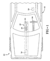
- a vehicle occupant safety system 20 is shown schematically in Figure 1 installed in a vehicle 22.
- the vehicle occupant safety system 20 generally includes a crash severity determination system 26 having a controller or CPU 28 and at least one crash sensor 30.
- the crash sensor 30 may be an inertial sensor, such as an accelerometer or a ball-in-tube sensor, or any other inertial sensor or other crash sensor.
- the crash determination system 26 may optionally include a second crash sensor 34, which again may be an inertial sensor, such as an accelerometer or ball-in-tube sensor, and/or may include radar.
- the crash severity determination system 26 generates an analog or continuously variable crash severity signal that is continuously variable from a minimum to a maximum.
- the crash severity signal is sent to at least one vehicle occupant safety device, such as an airbag 36 or other active restraint 38, such as a seat belt retractor, side airbag, seat bolsters, etc.
- the airbag module 36 is actuated in a continuously variable or "analog" manner. In other words, the amount of force with which the airbag module 36 deploys is not simply in discrete stages, but is continuously variable from its minimum actuation force to its maximum actuation force based upon the crash severity signal. Some airbag modules 36 are so activated by continuously varying the venting of the actuator; however, any technique may be used.
- the active restraint 38 is also continuously variable from its minimum actuation force to its maximum actuation force based upon the crash severity signal.
- the controller is preferably a CPU 28 with appropriate memory, hardware and software to perform the functions described herein, but alternatively could be a hardwired electronic circuit.
- the CPU 28 determines when to start calculating crash time, such as by determining when the crash signal from the crash sensor 30 (and/or optional crash sensor 34) crosses a first threshold (such as 2 Gs), which could be considered the "beginning of the crash.”
- the processor 28 determines a "crash time” from when the crash signal from the crash sensor 30 (and optionally crash sensor 34) crosses a second threshold.
- a “threshold crossing time" (or "TCT”) for each sensor 30, 34 is a function of each respective crash time.
- the processor 28 also determines crash type (i.e., frontal crash, car-to-car, pole, bumper override, etc.) based upon the crash signal from the crash sensor 30.
- the function f will vary based upon the types of sensors, locations of the sensors and the type of vehicle.
- crash severity g ⁇ v ⁇ Crash Type
- the function g will also vary based upon the types of sensors, locations of the sensors and the type of vehicle.
- the crash severity determination system 26 generates a crash severity signal which is a function of the inverse of the TCT(s) of the crash sensor(s) 30, 34.
- the crash severity signal is continuously variable for a given crash type from its minimum output to its maximum output.
- This continuously variable crash severity signal is sent to the vehicle occupant safety devices, including the airbag 36 and other active restraint 38 that in turn actuate proportionally to the crash severity signal in a continuously variable manner.
- crash time, change in velocity and crash type may be performed in many different ways. If the crash sensor 30 is an accelerometer, the processor 28 can determine the crash time and the crash type based upon the shape of the acceleration signal from the crash sensor 30. Alternatively, or in addition, if the vehicle occupant safety system 20 includes the optional sensor 34, the determination of crash type and/or the beginning of the crash may also be based upon the signals from the optional crash sensor 34. If the second crash sensor 34 is radar, the velocity can be determined directly. Many suitable algorithms, techniques, and sensors could be utilized to implement the present invention.
- Figure 2 illustrates the output of the crash severity determination system 26 of Figure 1 for a given crash type. As can be seen in Figure 2 , once the crash severity exceeds a minimum threshold the crash severity signal increases continuously variably, in an analog manner proportional to the crash severity. As shown in Figure 2 , this is a linear relationship between crash severity and the crash severity output signal.
Landscapes
- Engineering & Computer Science (AREA)
- Mechanical Engineering (AREA)
- Air Bags (AREA)
Claims (2)
- System zum Bestimmen der Schwere eines Fahrzeugaufpralls, das einen Aufprallsensor und ein Steuergerät zum Verarbeiten eines Aufprallsignals von dem Aufprallsensor umfasst, um die Schwere eines Aufpralls zu bestimmen und ein Aufprallschweresignal an eine Fahrzeuginsassen-Rückhaltevorrichtung zu senden, um zu bewirken, dass die Sicherheitsvorrichtung auf einem Niveau arbeitet, das proportional zu dem Steuersignal ist, dadurch gekennzeichnet, dass das Steuergerät Folgendes bestimmt:- wann das Aufprallsignal von dem Aufprallsensor eine erste Schwelle überschreitet und- wann das Aufprallsignal von dem Aufprallsensor eine zweite Schwelle überschreitet und- eine Aufprallschwere in Abhängigkeit von der Schwellenüberschreitungszeit (TCT), definiert als der Zeitabstand zwischen dem Überschreiten der ersten Schwelle und dem Überschreiten der zweiten Schwelle durch den Aufprallsensor,wobei das Aufprallschweresignal ein kontinuierlich veränderliches Signal mit unterschiedlichen Werten von einem Minimum bis zu einem Maximum an eine Fahrzeuginsassen-Rückhaltevorrichtung ist, die wiederum proportional zu dem Aufprallschweresignal auf eine kontinuierlich veränderliche Weise betätigt wird.
- System zum Bestimmen der Schwere eines Fahrzeugaufpralls nach Anspruch 1, wobei das Aufprallschweresignal eine Funktion des Umkehrwerts der Schwellenüberschreitungszeit (TCT) ist.
Applications Claiming Priority (3)
| Application Number | Priority Date | Filing Date | Title |
|---|---|---|---|
| US266168 | 1988-11-01 | ||
| US10/266,168 US6882914B2 (en) | 2002-10-07 | 2002-10-07 | Vehicle occupant safety system |
| PCT/US2003/018451 WO2004034248A1 (en) | 2002-10-07 | 2003-06-13 | Vehicle occupant safety system |
Publications (3)
| Publication Number | Publication Date |
|---|---|
| EP1550029A1 EP1550029A1 (de) | 2005-07-06 |
| EP1550029A4 EP1550029A4 (de) | 2006-02-08 |
| EP1550029B1 true EP1550029B1 (de) | 2008-05-14 |
Family
ID=32042618
Family Applications (1)
| Application Number | Title | Priority Date | Filing Date |
|---|---|---|---|
| EP03739091A Expired - Lifetime EP1550029B1 (de) | 2002-10-07 | 2003-06-13 | Fahrzeuginsassensicherheitssystem |
Country Status (5)
| Country | Link |
|---|---|
| US (1) | US6882914B2 (de) |
| EP (1) | EP1550029B1 (de) |
| AU (1) | AU2003245451A1 (de) |
| DE (1) | DE60321023D1 (de) |
| WO (1) | WO2004034248A1 (de) |
Families Citing this family (32)
| Publication number | Priority date | Publication date | Assignee | Title |
|---|---|---|---|---|
| DE10311524A1 (de) * | 2003-03-17 | 2004-09-30 | Robert Bosch Gmbh | Verfahren zur Auslösung von Rückhaltemitteln |
| US7207410B2 (en) * | 2004-04-29 | 2007-04-24 | Daimlerchrysler Corporation | Apparatus and method for enhanced impact sensing |
| DE102004059908A1 (de) * | 2004-12-13 | 2006-06-29 | Robert Bosch Gmbh | Verfahren und Vorrichtung zur Ansteuerung von Rückhaltemittel |
| DE102005015568A1 (de) * | 2005-04-05 | 2006-10-12 | Robert Bosch Gmbh | Vorrichtung zur Aufprallerkennung |
| US7263750B2 (en) | 2005-06-09 | 2007-09-04 | Amsafe, Inc. | Buckle assembly having single release for multiple belt connectors |
| US7980590B2 (en) | 2008-03-19 | 2011-07-19 | Amsafe, Inc. | Inflatable personal restraint systems having web-mounted inflators and associated methods of use and manufacture |
| US7665761B1 (en) | 2008-03-27 | 2010-02-23 | Amsafe, Inc. | Inflatable personal restraint systems and associated methods of use and manufacture |
| US8374751B2 (en) * | 2008-06-06 | 2013-02-12 | Chrysler Group Llc | Automotive impact sensing system |
| US8303043B2 (en) | 2008-09-29 | 2012-11-06 | Amsafe, Inc. (Phoenix Group) | Tensioning apparatuses for occupant restraint systems and associated systems and methods |
| US8469401B2 (en) | 2009-02-23 | 2013-06-25 | Amsafe, Inc. | Seat harness pretensioner |
| US8393645B2 (en) | 2009-11-02 | 2013-03-12 | Amsafe Commercial Products, Inc. | Devices for adjusting tension in seat belts and other restraint system webs, and associated methods |
| US8683666B2 (en) | 2009-11-04 | 2014-04-01 | Amsafe Commercial Products, Inc. | Restraint system buckle components having tactile surfaces, and associated methods of use and manufacture |
| US8627554B1 (en) | 2010-05-03 | 2014-01-14 | Amsafe, Inc. (Phoenix Group) | Buckle assemblies with swivel and dual release features and associated methods of use and manufacture |
| US8777323B2 (en) | 2010-07-20 | 2014-07-15 | Amsafe, Inc. | Restraint harnesses and associated methods of use and manufacture |
| USD661619S1 (en) | 2010-09-15 | 2012-06-12 | Amsafe Commercial Products, Inc. | Buckle assembly |
| USD655223S1 (en) | 2010-09-15 | 2012-03-06 | Amsafe Commercial Products, Inc. | Buckle assembly |
| DE102010052412B4 (de) * | 2010-11-24 | 2017-11-16 | Daimler Ag | Verfahren und Vorrichtung zum Schützen eines Fahrzeuginsassen in einem Fahrzeugsitz eines Fahrzeugs |
| US9156558B2 (en) | 2011-04-05 | 2015-10-13 | Amsafe, Inc. | Inflatable personal restraint systems |
| US8469397B2 (en) | 2011-04-13 | 2013-06-25 | Amsafe, Inc. | Stitch patterns for restraint-mounted airbags and associated systems and methods |
| US8439398B2 (en) | 2011-07-29 | 2013-05-14 | Amsafe, Inc. | Inflator connectors for inflatable personal restraints and associated systems and methods |
| US8523220B1 (en) | 2012-03-19 | 2013-09-03 | Amsafe, Inc. | Structure mounted airbag assemblies and associated systems and methods |
| US9511866B2 (en) | 2012-03-19 | 2016-12-06 | Amsafe, Inc. | Structure mounted airbag assemblies and associated systems and methods |
| US9022483B2 (en) | 2012-06-07 | 2015-05-05 | Shield Restraint Systems, Inc. | Seatbelt buckle tongue assembly |
| US9277788B2 (en) | 2013-02-19 | 2016-03-08 | Amsafe, Inc. | Dual release buckle assemblies and associated systems and methods |
| WO2014130485A1 (en) | 2013-02-19 | 2014-08-28 | Amsafe, Inc. | Buckle assemblies with lift latches and associated methods and systems |
| US9352839B2 (en) | 2014-10-02 | 2016-05-31 | Amsafe, Inc. | Active positioning airbag assembly and associated systems and methods |
| WO2016100566A1 (en) | 2014-12-16 | 2016-06-23 | Shield Restraint Systems, Inc. | Web adjusters for use with restraint systems and associated methods of use and manufacture |
| US9944245B2 (en) | 2015-03-28 | 2018-04-17 | Amsafe, Inc. | Extending pass-through airbag occupant restraint systems, and associated systems and methods |
| EP3283336B1 (de) | 2015-04-11 | 2019-11-20 | AmSafe, Inc. | Aktives entlüftungssystem für airbag |
| US10604259B2 (en) | 2016-01-20 | 2020-03-31 | Amsafe, Inc. | Occupant restraint systems having extending restraints, and associated systems and methods |
| US9814282B2 (en) | 2016-02-02 | 2017-11-14 | Shield Restraint Systems, Inc. | Harsh environment buckle assemblies and associated systems and methods |
| WO2018148221A1 (en) | 2017-02-07 | 2018-08-16 | Shield Restraint Systems, Inc. | Web adjuster |
Family Cites Families (8)
| Publication number | Priority date | Publication date | Assignee | Title |
|---|---|---|---|---|
| US5506775A (en) * | 1993-05-20 | 1996-04-09 | Kansei Corporation | Power source circuit for an occupant protecting device of motor vehicles |
| US5767766A (en) * | 1995-09-01 | 1998-06-16 | Southwest Research Institute | Apparatus and method for monitoring vehicular impacts using magnetostrictive sensors |
| CA2304479A1 (en) * | 1997-10-23 | 1999-04-29 | Breed Automotive Technology, Inc. | Crash detection system |
| JP3910293B2 (ja) * | 1998-03-12 | 2007-04-25 | カルソニックカンセイ株式会社 | サイドエアバッグユニット |
| JP3436185B2 (ja) * | 1999-02-09 | 2003-08-11 | トヨタ自動車株式会社 | 乗員保護装置の起動制御装置 |
| US6540255B1 (en) * | 1999-10-21 | 2003-04-01 | Siemens Vdo Automotive Corporation | Distributed electronic acceleration sensing for crash severity recognition |
| DE10140119C1 (de) * | 2001-08-16 | 2003-03-20 | Bosch Gmbh Robert | Vorrichtung zur Aufprallerkennung in einem Fahrzeug |
| US6629575B2 (en) * | 2002-04-24 | 2003-10-07 | Dimitar Nikolov | Vehicle occupant emergency system |
-
2002
- 2002-10-07 US US10/266,168 patent/US6882914B2/en not_active Expired - Lifetime
-
2003
- 2003-06-13 WO PCT/US2003/018451 patent/WO2004034248A1/en not_active Ceased
- 2003-06-13 EP EP03739091A patent/EP1550029B1/de not_active Expired - Lifetime
- 2003-06-13 DE DE60321023T patent/DE60321023D1/de not_active Expired - Lifetime
- 2003-06-13 AU AU2003245451A patent/AU2003245451A1/en not_active Abandoned
Also Published As
| Publication number | Publication date |
|---|---|
| AU2003245451A1 (en) | 2004-05-04 |
| US20040068355A1 (en) | 2004-04-08 |
| EP1550029A1 (de) | 2005-07-06 |
| WO2004034248A1 (en) | 2004-04-22 |
| US6882914B2 (en) | 2005-04-19 |
| EP1550029A4 (de) | 2006-02-08 |
| DE60321023D1 (de) | 2008-06-26 |
Similar Documents
| Publication | Publication Date | Title |
|---|---|---|
| EP1550029B1 (de) | Fahrzeuginsassensicherheitssystem | |
| US6915196B2 (en) | Method for operating a vehicle crash safety system in a vehicle having a pre-crash sensing system and countermeasure systems | |
| JP2941216B2 (ja) | 作動可能な拘束具を制御するための装置及び方法 | |
| KR100631268B1 (ko) | 자동차 에어백 시스템 | |
| EP1026052B1 (de) | Aktivierungsvorrichtung eines Rückhaltesystems für Kraftfahrzeug | |
| US7321817B2 (en) | Automobile frontal collision location detection for coordinated activation of safety systems | |
| US7912609B2 (en) | Motor vehicle comprising a preventive protective system | |
| EP1208021A1 (de) | Steuergerät für personenrückhaltesystem | |
| US7286920B2 (en) | Collision determining device | |
| EP1717108A2 (de) | System und Verfahren zur Erfassung von Boden und Bordstein getriggerten Überschlagereignissen | |
| JP2002046571A (ja) | 作動可能な乗員保護装置を制御するためのシステムおよび方法 | |
| US6459975B1 (en) | Method for recognizing the severity of a vehicle collision | |
| US7320478B2 (en) | Smart airbag for vehicular applications | |
| US20090150028A1 (en) | Motor vehicle with a safety system with a preventive action | |
| US7702441B2 (en) | Safety logic for vehicle rollover detection systems and a method for detecting near rollover situations | |
| CN1649758A (zh) | 用于控制一个回拉系统的装置 | |
| CN101031457A (zh) | 用于触发人员保护机构的方法和装置 | |
| US6304004B1 (en) | Apparatus for actuating a passenger safety system | |
| JP2008519720A (ja) | 乗員拘束装置を有する自動車 | |
| US20080185825A1 (en) | Device For Triggering a Second Airbag Stage | |
| US20190100177A1 (en) | Method for changing a forward displacement of an occupant of a vehicle during braking of the vehicle and control unit | |
| US20070007066A1 (en) | Peak load detection determination for deploying load limiting restraint devices | |
| KR100666360B1 (ko) | 차량 동역학에 근거한 충돌예방 안전장치 | |
| CN101896377A (zh) | 用于触发车辆的人员保护装置的方法及控制装置 | |
| JP4141999B2 (ja) | 車両用衝突判定装置 |
Legal Events
| Date | Code | Title | Description |
|---|---|---|---|
| PUAI | Public reference made under article 153(3) epc to a published international application that has entered the european phase |
Free format text: ORIGINAL CODE: 0009012 |
|
| 17P | Request for examination filed |
Effective date: 20050214 |
|
| AK | Designated contracting states |
Kind code of ref document: A1 Designated state(s): AT BE BG CH CY CZ DE DK EE ES FI FR GB GR HU IE IT LI LU MC NL PT RO SE SI SK TR |
|
| RBV | Designated contracting states (corrected) |
Designated state(s): DE ES FR GB IT |
|
| A4 | Supplementary search report drawn up and despatched |
Effective date: 20051227 |
|
| RIC1 | Information provided on ipc code assigned before grant |
Ipc: G06F 7/00 20060101AFI20040427BHEP Ipc: G06F 17/00 20060101ALI20051220BHEP Ipc: B60R 21/01 20060101ALI20051220BHEP |
|
| RIN1 | Information on inventor provided before grant (corrected) |
Inventor name: GIOUTSOS, TONY Inventor name: TABAR, DANIEL, N. |
|
| 17Q | First examination report despatched |
Effective date: 20060901 |
|
| GRAP | Despatch of communication of intention to grant a patent |
Free format text: ORIGINAL CODE: EPIDOSNIGR1 |
|
| GRAS | Grant fee paid |
Free format text: ORIGINAL CODE: EPIDOSNIGR3 |
|
| GRAA | (expected) grant |
Free format text: ORIGINAL CODE: 0009210 |
|
| AK | Designated contracting states |
Kind code of ref document: B1 Designated state(s): DE ES FR GB IT |
|
| REG | Reference to a national code |
Ref country code: GB Ref legal event code: FG4D |
|
| REF | Corresponds to: |
Ref document number: 60321023 Country of ref document: DE Date of ref document: 20080626 Kind code of ref document: P |
|
| PG25 | Lapsed in a contracting state [announced via postgrant information from national office to epo] |
Ref country code: ES Free format text: LAPSE BECAUSE OF FAILURE TO SUBMIT A TRANSLATION OF THE DESCRIPTION OR TO PAY THE FEE WITHIN THE PRESCRIBED TIME-LIMIT Effective date: 20080825 |
|
| PLBE | No opposition filed within time limit |
Free format text: ORIGINAL CODE: 0009261 |
|
| STAA | Information on the status of an ep patent application or granted ep patent |
Free format text: STATUS: NO OPPOSITION FILED WITHIN TIME LIMIT |
|
| 26N | No opposition filed |
Effective date: 20090217 |
|
| PG25 | Lapsed in a contracting state [announced via postgrant information from national office to epo] |
Ref country code: IT Free format text: LAPSE BECAUSE OF FAILURE TO SUBMIT A TRANSLATION OF THE DESCRIPTION OR TO PAY THE FEE WITHIN THE PRESCRIBED TIME-LIMIT Effective date: 20080514 |
|
| PGFP | Annual fee paid to national office [announced via postgrant information from national office to epo] |
Ref country code: GB Payment date: 20130529 Year of fee payment: 11 |
|
| PGFP | Annual fee paid to national office [announced via postgrant information from national office to epo] |
Ref country code: FR Payment date: 20130618 Year of fee payment: 11 |
|
| PGFP | Annual fee paid to national office [announced via postgrant information from national office to epo] |
Ref country code: DE Payment date: 20130628 Year of fee payment: 11 |
|
| REG | Reference to a national code |
Ref country code: DE Ref legal event code: R119 Ref document number: 60321023 Country of ref document: DE |
|
| GBPC | Gb: european patent ceased through non-payment of renewal fee |
Effective date: 20140613 |
|
| REG | Reference to a national code |
Ref country code: FR Ref legal event code: ST Effective date: 20150227 |
|
| REG | Reference to a national code |
Ref country code: DE Ref legal event code: R119 Ref document number: 60321023 Country of ref document: DE Effective date: 20150101 |
|
| PG25 | Lapsed in a contracting state [announced via postgrant information from national office to epo] |
Ref country code: DE Free format text: LAPSE BECAUSE OF NON-PAYMENT OF DUE FEES Effective date: 20150101 |
|
| PG25 | Lapsed in a contracting state [announced via postgrant information from national office to epo] |
Ref country code: FR Free format text: LAPSE BECAUSE OF NON-PAYMENT OF DUE FEES Effective date: 20140630 Ref country code: GB Free format text: LAPSE BECAUSE OF NON-PAYMENT OF DUE FEES Effective date: 20140613 |