EP1549982B1 - Drawer for the management of optical fibers - Google Patents
Drawer for the management of optical fibers Download PDFInfo
- Publication number
- EP1549982B1 EP1549982B1 EP03808178A EP03808178A EP1549982B1 EP 1549982 B1 EP1549982 B1 EP 1549982B1 EP 03808178 A EP03808178 A EP 03808178A EP 03808178 A EP03808178 A EP 03808178A EP 1549982 B1 EP1549982 B1 EP 1549982B1
- Authority
- EP
- European Patent Office
- Prior art keywords
- drawer
- drawers
- cassette
- cassettes
- array
- Prior art date
- Legal status (The legal status is an assumption and is not a legal conclusion. Google has not performed a legal analysis and makes no representation as to the accuracy of the status listed.)
- Expired - Lifetime
Links
- 239000013307 optical fiber Substances 0.000 title claims abstract description 42
- 239000000835 fiber Substances 0.000 claims abstract description 92
- 230000003287 optical effect Effects 0.000 claims description 3
- 230000000903 blocking effect Effects 0.000 description 7
- 238000003491 array Methods 0.000 description 6
- 230000008901 benefit Effects 0.000 description 5
- 238000009434 installation Methods 0.000 description 5
- 230000007246 mechanism Effects 0.000 description 5
- 238000013459 approach Methods 0.000 description 4
- 230000004048 modification Effects 0.000 description 4
- 238000012986 modification Methods 0.000 description 4
- 238000013461 design Methods 0.000 description 3
- 230000008520 organization Effects 0.000 description 3
- 238000000465 moulding Methods 0.000 description 2
- 238000006467 substitution reaction Methods 0.000 description 2
- 238000004026 adhesive bonding Methods 0.000 description 1
- 238000005452 bending Methods 0.000 description 1
- 238000004364 calculation method Methods 0.000 description 1
- 238000004590 computer program Methods 0.000 description 1
- 238000002474 experimental method Methods 0.000 description 1
- 238000001746 injection moulding Methods 0.000 description 1
- 238000003780 insertion Methods 0.000 description 1
- 230000037431 insertion Effects 0.000 description 1
- 238000000034 method Methods 0.000 description 1
- 230000008569 process Effects 0.000 description 1
- 230000008439 repair process Effects 0.000 description 1
- 238000000926 separation method Methods 0.000 description 1
- 238000003466 welding Methods 0.000 description 1
Images

Classifications
-
- G—PHYSICS
- G02—OPTICS
- G02B—OPTICAL ELEMENTS, SYSTEMS OR APPARATUS
- G02B6/00—Light guides; Structural details of arrangements comprising light guides and other optical elements, e.g. couplings
- G02B6/44—Mechanical structures for providing tensile strength and external protection for fibres, e.g. optical transmission cables
- G02B6/4439—Auxiliary devices
- G02B6/444—Systems or boxes with surplus lengths
- G02B6/4453—Cassettes
- G02B6/4455—Cassettes characterised by the way of extraction or insertion of the cassette in the distribution frame, e.g. pivoting, sliding, rotating or gliding
-
- G—PHYSICS
- G02—OPTICS
- G02B—OPTICAL ELEMENTS, SYSTEMS OR APPARATUS
- G02B6/00—Light guides; Structural details of arrangements comprising light guides and other optical elements, e.g. couplings
- G02B6/44—Mechanical structures for providing tensile strength and external protection for fibres, e.g. optical transmission cables
- G02B6/4439—Auxiliary devices
- G02B6/444—Systems or boxes with surplus lengths
- G02B6/4452—Distribution frames
- G02B6/44526—Panels or rackmounts covering a whole width of the frame or rack
Definitions
- the invention relates to a system that allows the management or organization of optical fibers to be used in an optical fiber telecommunication network. It relates more particularly to a system of drawers allowing the management of optical fibers including arrays of cassettes that may contain fiber splices.
- optical fibers have become more and more dominant in the telecommunication field. This results in a growing number of optical fibers that must be handled -- such as spliced, connected, and distributed -- and therefore systems for the management or organization of optical fibers are used to a growing extent. It is desirable to have an optimum organization of the fibers, and thus the ability to make modifications and changes in a controlled manner. These changes should preferably be carried out so that if at all possible only those optical fibers that have to be changed and modified are moved, while all other optical fibers essentially remain untouched so that undesired disturbances are avoided.
- cassettes have to be in some way mounted onto a modular optical distribution frame or rack, such as a 48.3 cm (19 inch) rack.
- a modular optical distribution frame or rack such as a 48.3 cm (19 inch) rack.
- the housings are arranged so that they can be rotated and then opened. This is particularly the case for the commonly used arrays of cassettes which are placed on rails or racks so that they can be flipped like pages of a book, as described in WO-A-95/07481 and WO-A-94/23324 . In all these cases it is necessary to open some kind of a door in order to access a single cassette.
- Document EP-A-0 689 074 discloses a housing wherein one single drawer is slidably mounted. A drawer is slidable between a retracted and an extended position. The drawer carries splicing cassettes which interior is only accessible when the drawer is in its extended position.
- the splicing cassettes are pivotally around a horizontal axis. If a fiber or fiber connection in the lowest splicing cassette of the cassettes stack has to be accessed, every splicing cassette on top of the lowest splicing cassette has to be pivoted upwardly.
- the invention suggests a system of drawers arranged in a housing into which the incoming fibers are introduced the housing having a back side and a front side, the incoming fibers to be introduced at the backside, the front side comprising for each individual drawer an array of connectors and an array of fiber optic splicing cassettes which can be accessed from the front side without opening the drawer.
- the connectors are provided with a length of optical fibers, which can be entered into the individual splicing cassettes where they could be spliced together with the incoming fibers.
- More guiding means are introduced in the drawer allowing a guidance of the optical fibers. This is possible both for the incoming fibers as well as the fibers being connected to the fiber optic connectors.
- the drawers are designed so that they can be individually moved out of the housing in order to allow a direct access to the optical fibers to be handled.
- the drawers are moved on rails or other telescopic devices resulting in a parallel movement of the front side.
- the individual drawers can be rotated around an axis.
- This axis is preferably arranged at one front end of the drawer and it should be so designed that the drawer is accessible for the handling of the optical fibers.
- the angle of rotation is below 90° to minimize the movement of the optical fibers.
- the array of splicing cassettes is arranged so that every individual splicing cassette can be moved out of the system without the opening of the drawer.
- the area for the rotation axis of the splicing cassettes is near the front side of the drawer. More preferably the rotation angle for the individual splicing cassette is less than 90°, or more preferably less than below 60°.
- the splicing cassettes can be rotated around a fixed axis common to all splicing cassettes of the array within the drawer.
- the splicing cassettes are rotated so that they simultaneously are also linearly moved out of the drawer.
- a third embodiment comprises a drawer system with an array of cassettes having a width and a longitudinal extension larger than the width and a thickness significantly smaller than the width.
- the cassettes are arranged between two side plates which are connected with each other with at least two fixing means that are spaced apart by a given distance whereby the cassettes are provided with at least two curved slots the first one being arranged towards a first longitudinal end of the cassettes and the second one being arranged further inside the cassette and being longer than the first slot.
- the cassettes are mounted between the two side plates so that the two fixing means pass through the slots.
- These slots are essentially curved and so designed that an individual cassette can be moved out of the array whereby it is rotated at the first longitudinal end and simultaneously lifted out of the stack in a direction which is perpendicular to the longitudinal direction of the cassette.
- a fourth embodiment comprises a drawer system with an array of cassettes having cassettes which can be moved on rails or other telescopic devices resulting in parallel movement to the front side to get access to each individual cassette without moving the others.
- the cassette is so designed that the incoming and outgoing fibers pass into the cassette close to the ends of the curved slots and at the first longitudinal end of the cassette.
- the individual drawers can preferably be provided with guides both for the incoming fibers as well as for the fibers being connected to the fiber optic connectors so that it is possible to guide them more or less directly into a given individual cassette of the array of fiber optic splicing cassettes.
- guides for example in the form of tubes or deflectors so that it is possible to access any cassette from the backside of each drawer. In one configuration this would require to have as many separate guides as cassettes are placed in the drawer.
- a smaller number of guides is used where the fibers are guided to a fan-out element which is adjacent to the array of cassettes and where it is possible to allow the fibers to exit the drawer so that they can be manually fed into one of the cassettes.
- One advantage is that in these particular cases it is possible to introduce optical fibers into the drawer without opening this drawer and by only opening the involved cassette. By this approach it is ensured that the disturbance of all the other fibers is brought to a minimum.
- the system comprising the stack of cassettes is preferably produced through conventional molding processes.
- the first longitudinal end of the cassettes is provided with two pairs of curved slots, two first ones and two longer second ones which are symmetrically arranged with respect to the longitudinal extension of the cassette.
- an array of cassettes is arranged so that they are placed in a manner that when opening the cassette the fibers can be accessed from the top. It is therefore desirable to have arrangements, which are rotated around axes, which are arranged on the right side or left side of the array when standing in front of it.
- the configuration with two pairs of axes allows to create arrays of cassettes arranged between the two side plates so that the axis configuration is either on the left side or the right side when arranging the stack so that in the practical use the cassettes are accessed from the top.
- a blocking means is placed into the one of the second slots, which in the specific configuration is not used.
- this blocking means is simultaneously molded with the cassette so that it can be easily broken off from it being arranged at a place, which is uncritical for the use of the cassette.
- this blocking means can be broken off so that two small pins are left over at the longitudinal end of the cassette being arranged so that they face each other so that they can be used in order to arrange a cassette in the conventional orientation where individual cassettes are moved over each other like pages in a book.
- This is of course not a preferred configuration but the advantage is that the cassettes could also be utilized in a conventional side by side arrangement where the cassettes are moved with respect to each other.
- a device for managing optical fibers, in which the device includes a drawer that carries a plurality of optical fiber cassettes, wherein the drawer can be extended from a frame to provide access to all of the cassettes.
- a drawer is provided that comprises a plurality of fiber cassettes, wherein the system is so designed that it is possible to open an individual cassette without opening the drawer and without opening the other cassettes. Further modifications include providing guides such as fiber optic tubes.
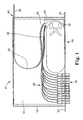
- FIG. 1 provides a top view of an individual drawer 12 arranged in a housing 14.
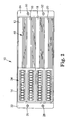
- Figure 2 provides a front view of the same configuration, which shows a total of four drawers 12, 16, 18, 20, which are arranged one on top of the other.
- the housing is provided with lateral flanges 22, 24 that have holes 26, 28, 30, 32, so that the entire housing 14 can be mounted on to a 48.63 mm (19 inch) rack.
- the same type of housing with any given number of drawers can also be designed, so that it can be assembled onto a modular optical distribution frame (MODF).
- MODF modular optical distribution frame
- Figure 1 shows one arrangement within a drawer.
- an array 34 of fiber optic connectors can be seen. Each connector is connected to an optical fiber in the fiber arrangement 36.
- An incoming optical fiber tube 38 enters the housing 14 on the rear side 40. It should be understood that there can be one or more optical fiber tubes 38 and only one is depicted, which typically is a tube that contains several (often from 4 to 12) optical fibers.
- the incoming optical fiber tube is bent typically in two different directions 42, 44, so that it reaches the array of fiber optic splicing cassettes 46. Typically, the bending is obtained through an appropriate guide, housing or tube, one of which is shown in Figure 1 at 48.
- the incoming fiber tube then enters another first fan out element 50 that is typically part of the array of fiber optic splicing cassettes 46.
- the fibers of the incoming fiber tube 38 are distributed inside the fan out element into pairs of fibers and then enters each of the cassettes in the array 46, which is not further shown in detail but commonly known.
- the individual fibers coming from the array of fiber optic connectors 34 are guided by a second guide 52, so that they also reach the corresponding fiber optic splicing cassettes.
- the splicing is achieved, which is well-known to someone skilled in the art and is described in, for example, WO 95/07481 .
- There is a preferably a well-defined distribution of fibers within the fan-out element so that each individual fiber tube 38 leads to a predetermined cassette, allowing a fiber to pass from the back side directly into the cassette.
- the drawer of the present invention can be moved out of the housing in some manner, provided with an array of fiber optic connectors and an array of splicing cassettes, which can be accessed without opening the drawer.
- the fiber tubes 38 are designed so that it is possible to directly guide a fiber from the backside of the drawer on the rear side 40 so that it can be guided into a given cassette. Therefore the number of the optical fiber tubes, 38 corresponds to the number of the cassettes.
- the particular advantage resulting from this is that it is possible to insert an additional incoming fiber or set of additional in-coming fibers by inserting them at a given drawer into that optical fiber tube 38 that corresponds to the cassette into which the fiber should be guided.
- Figure 3 shows the function of a first embodiment of the drawer, which is in the closed position as shown in Figure 1 , showing housing 14, drawer 12 with the array of fiber optic connectors 34, the array of fiber optic splicing cassettes 46. Also shown is the internal fiber wiring 36 and the incoming tube of optical fibers 38, which reaches housing 14, preferably on the rear side 40.
- the housing 14 comprises a rear wall 54 and side walls 56, 58. Rails 60, 62 are attached onto the side walls 56, 58 so that the drawer can be moved onto these rails. This is done for each drawer within the system. This means in a configuration according to Figure 2 , there are four pairs of rails to support the drawers 12, 16, 18, 20.
- the rails 60, 62 are of the standard type, and the drawer 12 moves along those in a well-known manner and is also provided with a blocking mechanism to prevent the drawer from falling off the housing if the drawer is extended too far.
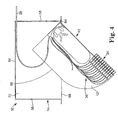
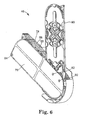
- Figure 4 shows another embodiment, in which the drawer 12 is attached to the housing on an axis 64 on the right side of the side wall 58 on the front portion.
- the rear side of drawer 12 is provided with a rounded corner 66, which is designed to enable the drawer 12 to move in and out of housing 14.
- Line 68 shows the front line of the housing, which can be either the next drawer or a horizontal separation wall 70 between two adjacent drawers. It depends on the detailed requirements whether such an additional wall is needed or not.
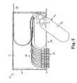
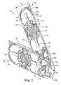
- Figure 5 shows in more detail the advantages of the system for accessing an individual fiber optic splicing cassette, without the need to open the respective drawer in which it is placed. It shows the entire system 10 with housing 14 and a top view of drawer 12, in the incoming fiber optic tubes 38 the array of fiber optic connectors 34, the corresponding fiber optic cabling internally from these connectors 36 and especially the array of fiber optic splicing cassettes 46. As shown, one of the splicing cassettes 72 is moved out of the array 46 utilizing a mechanical configuration 74, that not only allows the fiber optic splicing cassette 72 to rotate, but simultaneously to extend it out of the drawer system.
- the array 46 of fiber optic splicing cassettes consists of two side plates 76, 78 that are fixedly held together with three axes or rods 80, 82, 84, which will be explained in further details below. Between these side plates 76, 78 six cassettes for the management of the optical fibers are placed, which also will be explained in further detail in conjunction with the description for Figure 7 , only three of them 86, 88, 90 are referred to. In Figure 6 the cassette 90 next to the side plate 76 is moved out the array while in Figure 7 the first cassette 86 close to side plate 78 is moved out while the next cassette 88 is left in the system.
- This cassette has a longitudinal extension, which is indicated by the double arrow 92 and a width 94.
- the longitudinal extension is significantly larger than the width 94.
- the cassette essentially consists of a base plate 96 and is at its circumference surrounded by an outer wall 98, which only with some interruptions is arranged at the entire circumference. This is a preferred configuration. It is also possible to only have such a wall at portions of the circumference but preferable the entire circumference is provided with this wall to obtain a maximum protection for the optical fibers.
- the height of wall 98 essentially determines the thickness of the cassette 86.
- Cassette 86 is placed within the array by the axes 80, 82. This is achieved, so that is possible that cassette 86 like all the other cassettes can be moved out of the array as depicted from the first longitudinal end 100. Cassette 86 can be moved out of the array at the second longitudinal end 102 utilizing a handle like configuration of some kind 104. This is designed, so that it is possible to grasp one of the cassettes that is supposed to be moved out of the array.
- the handle 104 is preferably provided with means for marking of some kind at least a numbering or the like, so that is possible to identify the cassette that is supposed to be opened.
- Side plate 78 is provided with axes 80, 82, 84, which are fixedly mounted onto side plate 78.
- the cassettes are placed onto the axes through a first curved slot 106 and a second curved slot 108.
- the cassettes are moved on to axes 80, 82 through slots 106, 108 sequentially starting with cassette 86, then 88 etc.
- the second side plate 76 is placed on to axes 80, 82, 84 ( Fig. 6 ) and fixedly mounted to it. This can be done in any way through a specially designed snapping mechanism, ultrasonic welding, gluing etc.
- Figure 7 further allows to describe in which way an individual cassette can be moved out of the array. This is achieved through a special design of curved slots 106, 108.
- curved slot 106 has a right end 110 and a left end 112.
- Slot 108 has a right end 114 and a left end 116.
- the axes 80, 82 touch the left ends 112, 116 of curved slots 106, 108.
- the cassette is guided through axes 80, 82 until these axes touch the right ends 110, 114 of curved slots 106, 108.
- Cassette 86 is can be made by injection molding, and comprises a base plate 96 and a side wall 98 as described above. It furthermore contains molded in configurations 118, 120, 122, 124, 126, which project from the upper side of the wall 98 on the base plate 96 corresponding openings are provided in order to allow a molding of this component without the use of any drawers. These devices provide possibilities to maintain the optical fibers that are guided inside the cassette and to keep them in place. The same applies to the fingers 128, 130 that are provided in the middle and where also in the base plate 96 corresponding openings are left for the same reason.
- the circular middle portion in the base plate 96 designated with 132 provides means for the fixing of the fiber optic splices.
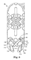
- Figures 8 and 9 explain more in detail the purpose of the use of a first pair of curved slots 106, 108 and a second pair of curved slots 134, 136.
- the configuration in Figure 8 essentially shows the positioning of the cassette and the axes 80, 82 that are supposed to hold cassette 86 as in Figure 7 , mainly in a closed position.
- Axes 80, 82 touch slots 106, 108 at their ends 112, 116 opposite to the first longitudinal end 100.
- a blocking component 137 is arranged in slot 136.
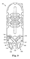
- the double configuration with the two pairs of slots 106, 108 and 134, 136 allows to use the very same component for this alternative arrangement where for example the cassette is not moved from the right but from the left side or vice versa.
- This alternative configuration can be seen in Figure 9 .
- the same kind of cassette that is then movable from the other side is guided again through the axes 80, 82, which however move in slots 134, 136.
- the axes In the closed position they touch the ends 140, 144 opposite to the first longitudinal end 100 as shown.
- the axes move along the slots 134, 136 until they reach the opposite ends 138, 142 close to the first longitudinal end 100 as depicted.
- the blocking component 137 accordingly is placed into slot 108.
- the invention provides complete access to all functional elements for the initial installation of the optical fibers, and only access to the splice area for re-splicing. This can be done without movement of any adjacent cassette and therefore without disturbing others fibers.
- the drawers can be designed to provide the features desired, including by telescoping outward, swiveling, or other mechanisms. All work can be done with access to the front of the array of cassettes, and different sizes and types of cassettes can be used.
- Substitution of fiber wiring 36 by new pigtails or fixed fibres or later installation of the pigtails can be done from front side without opening the drawer, by using guiding tubes or elements that guide the pigtail fibers from the front entry position via fan out element to the individual splice cassettes.
- Substitution or later installation of fiber tubes can be done from front side without opening the drawer by using guiding tubes or elements that guide the fiber tubes from rear entry via a second fan out element to the front where they can be distributed to the cassettes.
Landscapes
- Physics & Mathematics (AREA)
- General Physics & Mathematics (AREA)
- Optics & Photonics (AREA)
- Light Guides In General And Applications Therefor (AREA)
- Optical Couplings Of Light Guides (AREA)
Applications Claiming Priority (3)
| Application Number | Priority Date | Filing Date | Title |
|---|---|---|---|
| US41781802P | 2002-10-11 | 2002-10-11 | |
| US417818P | 2002-10-11 | ||
| PCT/US2003/031892 WO2004034116A1 (en) | 2002-10-11 | 2003-10-09 | Drawer for the management of optical fibers |
Publications (2)
| Publication Number | Publication Date |
|---|---|
| EP1549982A1 EP1549982A1 (en) | 2005-07-06 |
| EP1549982B1 true EP1549982B1 (en) | 2008-07-16 |
Family
ID=32094098
Family Applications (1)
| Application Number | Title | Priority Date | Filing Date |
|---|---|---|---|
| EP03808178A Expired - Lifetime EP1549982B1 (en) | 2002-10-11 | 2003-10-09 | Drawer for the management of optical fibers |
Country Status (12)
Cited By (1)
| Publication number | Priority date | Publication date | Assignee | Title |
|---|---|---|---|---|
| EP3698192A4 (en) * | 2017-10-17 | 2021-09-22 | Corning Research And Development Corporation | ENCLOSURE FOR OPTICAL FIBER SPLICE |
Families Citing this family (170)
| Publication number | Priority date | Publication date | Assignee | Title |
|---|---|---|---|---|
| US6760531B1 (en) | 1999-03-01 | 2004-07-06 | Adc Telecommunications, Inc. | Optical fiber distribution frame with outside plant enclosure |
| CA2398809A1 (en) * | 2000-02-07 | 2001-08-09 | Te Huruhuru Properties Ltd. | A portable ski tow |
| JP4390705B2 (ja) | 2002-10-11 | 2009-12-24 | スリーエム イノベイティブ プロパティズ カンパニー | 光ファイバスプライシングカセットのアレイ |
| US7142764B2 (en) | 2003-03-20 | 2006-11-28 | Tyco Electronics Corporation | Optical fiber interconnect cabinets, termination modules and fiber connectivity management for the same |
| US7198409B2 (en) | 2003-06-30 | 2007-04-03 | Adc Telecommunications, Inc. | Fiber optic connector holder and method |
| US7233731B2 (en) | 2003-07-02 | 2007-06-19 | Adc Telecommunications, Inc. | Telecommunications connection cabinet |
| US6983095B2 (en) * | 2003-11-17 | 2006-01-03 | Fiber Optic Network Solutions Corporation | Systems and methods for managing optical fibers and components within an enclosure in an optical communications network |
| US7369741B2 (en) | 2003-11-17 | 2008-05-06 | Fiber Optics Network Solutions Corp. | Storage adapter with dust cap posts |
| US7218827B2 (en) | 2004-06-18 | 2007-05-15 | Adc Telecommunications, Inc. | Multi-position fiber optic connector holder and method |
| WO2006012389A1 (en) * | 2004-07-22 | 2006-02-02 | Panduit Corp. | Front access punch down patch panel |
| US7268299B2 (en) | 2004-08-11 | 2007-09-11 | 3M Innovative Properties Company | Telecommunications cable enclosure |
| US7256349B2 (en) | 2004-08-11 | 2007-08-14 | 3M Innovative Properties Company | Telecommunications cable enclosure |
| PL2843453T3 (pl) * | 2005-02-16 | 2017-09-29 | 3M Innovative Properties Company | Modułowa głowica kablowa dla sieci optycznych |
| US7362942B2 (en) | 2005-03-02 | 2008-04-22 | Adc Telecommunications, Inc. | System and method of grounding fiber storage trays |
| US7194181B2 (en) | 2005-03-31 | 2007-03-20 | Adc Telecommunications, Inc. | Adapter block including connector storage |
| US7460758B2 (en) * | 2005-06-03 | 2008-12-02 | Telect Inc. | Fiber management system |
| US7366391B2 (en) * | 2005-06-03 | 2008-04-29 | Telect Inc. | Hybrid wire-fiber management |
| US7254307B2 (en) | 2005-06-03 | 2007-08-07 | Telect Inc. | Fiber breakout system |
| US7683270B2 (en) * | 2005-06-03 | 2010-03-23 | Telect Inc. | Telecommunications cabinet |
| US7284994B2 (en) * | 2005-06-21 | 2007-10-23 | Adc Telecommunications, Inc. | Grounding lug for armored cable and method |
| US7623749B2 (en) | 2005-08-30 | 2009-11-24 | Adc Telecommunications, Inc. | Fiber distribution hub with modular termination blocks |
| EP1949156B1 (en) * | 2005-10-24 | 2021-08-04 | Corning Research & Development Corporation | Optical connector and method of use |
| US7720343B2 (en) | 2006-02-13 | 2010-05-18 | Adc Telecommunications, Inc. | Fiber distribution hub with swing frame and modular termination panels |
| US7816602B2 (en) | 2006-02-13 | 2010-10-19 | Adc Telecommunications, Inc. | Fiber distribution hub with outside accessible grounding terminals |
| US7773850B2 (en) * | 2006-03-13 | 2010-08-10 | Panduit Corp. | Cable slack manager |
| US7760984B2 (en) | 2006-05-04 | 2010-07-20 | Adc Telecommunications, Inc. | Fiber distribution hub with swing frame and wrap-around doors |
| US7454113B2 (en) | 2006-07-20 | 2008-11-18 | Adc Telecommunications, Inc. | Grounding device for fiber storage trays |
| US7509015B2 (en) * | 2006-07-26 | 2009-03-24 | Ortronics, Inc. | Secure fiber optic network cassette assembly |
| US7689089B2 (en) * | 2006-10-11 | 2010-03-30 | Panduit Corp. | Release latch for pre-terminated cassette |
| US7600720B2 (en) * | 2006-11-29 | 2009-10-13 | Panduit Corp. | Horizontal cable manager |
| CN101195453A (zh) * | 2006-12-05 | 2008-06-11 | 3M创新有限公司 | 线缆松弛处理设备 |
| US7496268B2 (en) * | 2006-12-13 | 2009-02-24 | Corning Cable Systems Llc | High density fiber optic hardware |
| AU2006352360B2 (en) * | 2006-12-27 | 2013-10-17 | Prysmian Cables & Systems Limited | Optical fibre management system |
| US7349616B1 (en) | 2007-01-12 | 2008-03-25 | Corning Cable Systems Llc | Fiber optic local convergence points for multiple dwelling units |
| US7822310B2 (en) | 2007-02-28 | 2010-10-26 | Corning Cable Systems Llc | Fiber optic splice trays |
| US8798427B2 (en) | 2007-09-05 | 2014-08-05 | Corning Cable Systems Llc | Fiber optic terminal assembly |
| US8059932B2 (en) | 2007-10-01 | 2011-11-15 | Clearfield, Inc. | Modular optical fiber cassette |
| US20090310929A1 (en) * | 2007-10-10 | 2009-12-17 | Adc Telecommunications, Inc. | Optical fiber interconnection apparatus |
| US7751672B2 (en) | 2007-10-31 | 2010-07-06 | Adc Telecommunications, Inc. | Low profile fiber distribution hub |
| US8229265B2 (en) | 2007-11-21 | 2012-07-24 | Adc Telecommunications, Inc. | Fiber distribution hub with multiple configurations |
| US7889961B2 (en) | 2008-03-27 | 2011-02-15 | Corning Cable Systems Llc | Compact, high-density adapter module, housing assembly and frame assembly for optical fiber telecommunications |
| CN101583256A (zh) * | 2008-05-12 | 2009-11-18 | 爱德龙通讯系统(上海)有限公司 | 电缆管理面板 |
| GB2460452B (en) * | 2008-05-30 | 2011-03-09 | Brand Rex Ltd | Improvements in and relating to optical fibre patch panels |
| EP2321681B1 (en) | 2008-08-27 | 2015-10-28 | ADC Telecommunications, Inc. | Fiber optic adapter with integrally molded ferrule alignment structure |
| US8184938B2 (en) * | 2008-08-29 | 2012-05-22 | Corning Cable Systems Llc | Rear-installable fiber optic modules and equipment |
| US11294135B2 (en) | 2008-08-29 | 2022-04-05 | Corning Optical Communications LLC | High density and bandwidth fiber optic apparatuses and related equipment and methods |
| US8452148B2 (en) | 2008-08-29 | 2013-05-28 | Corning Cable Systems Llc | Independently translatable modules and fiber optic equipment trays in fiber optic equipment |
| US8290330B2 (en) * | 2008-09-05 | 2012-10-16 | Adc Gmbh | Patch panel assembly |
| CN102209921B (zh) | 2008-10-09 | 2015-11-25 | 康宁光缆系统有限公司 | 具有支持来自光学分路器的输入和输出光纤的适配器面板的光纤终端 |
| US8879882B2 (en) | 2008-10-27 | 2014-11-04 | Corning Cable Systems Llc | Variably configurable and modular local convergence point |
| US8417074B2 (en) | 2008-11-21 | 2013-04-09 | Adc Telecommunications, Inc. | Fiber optic telecommunications module |
| EP2221932B1 (en) | 2009-02-24 | 2011-11-16 | CCS Technology Inc. | Holding device for a cable or an assembly for use with a cable |
| DE102009013299B3 (de) * | 2009-03-16 | 2010-10-28 | Adc Gmbh | Patch-Panel für einen optischen Verteiler |
| EP2237091A1 (en) | 2009-03-31 | 2010-10-06 | Corning Cable Systems LLC | Removably mountable fiber optic terminal |
| US8699838B2 (en) | 2009-05-14 | 2014-04-15 | Ccs Technology, Inc. | Fiber optic furcation module |
| US9075216B2 (en) | 2009-05-21 | 2015-07-07 | Corning Cable Systems Llc | Fiber optic housings configured to accommodate fiber optic modules/cassettes and fiber optic panels, and related components and methods |
| US8538226B2 (en) | 2009-05-21 | 2013-09-17 | Corning Cable Systems Llc | Fiber optic equipment guides and rails configured with stopping position(s), and related equipment and methods |
| WO2010148336A1 (en) | 2009-06-19 | 2010-12-23 | Corning Cable Systems Llc | High density and bandwidth fiber optic apparatuses and related equipment and methods |
| CN102804014A (zh) | 2009-06-19 | 2012-11-28 | 康宁电缆系统有限责任公司 | 高光纤电缆封装密度装置 |
| US8712206B2 (en) | 2009-06-19 | 2014-04-29 | Corning Cable Systems Llc | High-density fiber optic modules and module housings and related equipment |
| ES2403007A1 (es) * | 2009-07-01 | 2013-05-13 | Adc Telecommunications, Inc | Concentrador de distribución de fibra para montaje en pared. |
| US8467651B2 (en) | 2009-09-30 | 2013-06-18 | Ccs Technology Inc. | Fiber optic terminals configured to dispose a fiber optic connection panel(s) within an optical fiber perimeter and related methods |
| US8625950B2 (en) | 2009-12-18 | 2014-01-07 | Corning Cable Systems Llc | Rotary locking apparatus for fiber optic equipment trays and related methods |
| DE102009060626A1 (de) | 2009-12-24 | 2011-06-30 | Klapproth, Holger, Dr., 79108 | Kalibrierte Flusszelle zur IR-Analytik |
| DE102010006611B4 (de) * | 2010-02-01 | 2012-11-08 | Adc Gmbh | Halterung für mindestens eine Kassette |
| US8992099B2 (en) | 2010-02-04 | 2015-03-31 | Corning Cable Systems Llc | Optical interface cards, assemblies, and related methods, suited for installation and use in antenna system equipment |
| CN102870021B (zh) | 2010-03-02 | 2015-03-11 | 蒂安电子服务有限责任公司 | 光纤通信模块 |
| US8649649B2 (en) | 2010-03-03 | 2014-02-11 | Adc Telecommunications, Inc. | Fiber distribution hub with connectorized stub cables |
| US9547144B2 (en) | 2010-03-16 | 2017-01-17 | Corning Optical Communications LLC | Fiber optic distribution network for multiple dwelling units |
| US20110235986A1 (en) * | 2010-03-24 | 2011-09-29 | Adc Telecommunications, Inc. | Optical fiber drawer with connectorized stub cable |
| US8913866B2 (en) | 2010-03-26 | 2014-12-16 | Corning Cable Systems Llc | Movable adapter panel |
| US8792767B2 (en) | 2010-04-16 | 2014-07-29 | Ccs Technology, Inc. | Distribution device |
| CN102884469B (zh) | 2010-04-16 | 2016-09-28 | Ccs技术股份有限公司 | 用于数据电缆的密封及应变消除装置 |
| EP2381284B1 (en) | 2010-04-23 | 2014-12-31 | CCS Technology Inc. | Under floor fiber optic distribution device |
| US9075217B2 (en) | 2010-04-30 | 2015-07-07 | Corning Cable Systems Llc | Apparatuses and related components and methods for expanding capacity of fiber optic housings |
| US8660397B2 (en) | 2010-04-30 | 2014-02-25 | Corning Cable Systems Llc | Multi-layer module |
| US9720195B2 (en) | 2010-04-30 | 2017-08-01 | Corning Optical Communications LLC | Apparatuses and related components and methods for attachment and release of fiber optic housings to and from an equipment rack |
| US8879881B2 (en) | 2010-04-30 | 2014-11-04 | Corning Cable Systems Llc | Rotatable routing guide and assembly |
| US8705926B2 (en) | 2010-04-30 | 2014-04-22 | Corning Optical Communications LLC | Fiber optic housings having a removable top, and related components and methods |
| US9519118B2 (en) | 2010-04-30 | 2016-12-13 | Corning Optical Communications LLC | Removable fiber management sections for fiber optic housings, and related components and methods |
| US9632270B2 (en) | 2010-04-30 | 2017-04-25 | Corning Optical Communications LLC | Fiber optic housings configured for tool-less assembly, and related components and methods |
| US8891927B2 (en) | 2010-05-07 | 2014-11-18 | Adc Telecommunications, Inc. | Fiber distribution hub with pass-through interfaces |
| PL3594729T3 (pl) | 2010-06-23 | 2021-11-22 | Corning Research & Development Corporation | Szafa światłowodowa i podnośnik szafy |
| US8718436B2 (en) | 2010-08-30 | 2014-05-06 | Corning Cable Systems Llc | Methods, apparatuses for providing secure fiber optic connections |
| WO2012054454A2 (en) | 2010-10-19 | 2012-04-26 | Corning Cable Systems Llc | Transition box for multiple dwelling unit fiber optic distribution network |
| US9279951B2 (en) | 2010-10-27 | 2016-03-08 | Corning Cable Systems Llc | Fiber optic module for limited space applications having a partially sealed module sub-assembly |
| US8662760B2 (en) | 2010-10-29 | 2014-03-04 | Corning Cable Systems Llc | Fiber optic connector employing optical fiber guide member |
| US9116324B2 (en) | 2010-10-29 | 2015-08-25 | Corning Cable Systems Llc | Stacked fiber optic modules and fiber optic equipment configured to support stacked fiber optic modules |
| EP2646867B1 (en) | 2010-11-30 | 2018-02-21 | Corning Optical Communications LLC | Fiber device holder and strain relief device |
| EP2671109A2 (en) | 2011-02-02 | 2013-12-11 | Corning Cable Systems LLC | Dense fiber optic connector assemblies and related connectors and cables suitable for establishing optical connections for optical backplanes in equipment racks |
| US9008485B2 (en) | 2011-05-09 | 2015-04-14 | Corning Cable Systems Llc | Attachment mechanisms employed to attach a rear housing section to a fiber optic housing, and related assemblies and methods |
| JP5901150B2 (ja) * | 2011-06-06 | 2016-04-06 | 株式会社昭電 | 光配線部 |
| CN103649805B (zh) | 2011-06-30 | 2017-03-15 | 康宁光电通信有限责任公司 | 使用非u宽度大小的外壳的光纤设备总成以及相关方法 |
| US8953924B2 (en) | 2011-09-02 | 2015-02-10 | Corning Cable Systems Llc | Removable strain relief brackets for securing fiber optic cables and/or optical fibers to fiber optic equipment, and related assemblies and methods |
| US9229172B2 (en) | 2011-09-12 | 2016-01-05 | Commscope Technologies Llc | Bend-limited flexible optical interconnect device for signal distribution |
| US9417418B2 (en) | 2011-09-12 | 2016-08-16 | Commscope Technologies Llc | Flexible lensed optical interconnect device for signal distribution |
| US9170391B2 (en) | 2011-10-07 | 2015-10-27 | Adc Telecommunications, Inc. | Slidable fiber optic connection module with cable slack management |
| US9002166B2 (en) | 2011-10-07 | 2015-04-07 | Adc Telecommunications, Inc. | Slidable fiber optic connection module with cable slack management |
| ES2855523T3 (es) | 2011-10-07 | 2021-09-23 | Commscope Technologies Llc | Casete de fibra óptica, sistema y método |
| WO2013052854A2 (en) | 2011-10-07 | 2013-04-11 | Adc Telecommunications, Inc. | Slidable fiber optic connection module with cable slack management |
| US9038832B2 (en) | 2011-11-30 | 2015-05-26 | Corning Cable Systems Llc | Adapter panel support assembly |
| US9219546B2 (en) | 2011-12-12 | 2015-12-22 | Corning Optical Communications LLC | Extremely high frequency (EHF) distributed antenna systems, and related components and methods |
| US9075203B2 (en) | 2012-01-17 | 2015-07-07 | Adc Telecommunications, Inc. | Fiber optic adapter block |
| US10110307B2 (en) | 2012-03-02 | 2018-10-23 | Corning Optical Communications LLC | Optical network units (ONUs) for high bandwidth connectivity, and related components and methods |
| US9004778B2 (en) | 2012-06-29 | 2015-04-14 | Corning Cable Systems Llc | Indexable optical fiber connectors and optical fiber connector arrays |
| US9250409B2 (en) | 2012-07-02 | 2016-02-02 | Corning Cable Systems Llc | Fiber-optic-module trays and drawers for fiber-optic equipment |
| US9049500B2 (en) | 2012-08-31 | 2015-06-02 | Corning Cable Systems Llc | Fiber optic terminals, systems, and methods for network service management |
| US9042702B2 (en) | 2012-09-18 | 2015-05-26 | Corning Cable Systems Llc | Platforms and systems for fiber optic cable attachment |
| US9146362B2 (en) | 2012-09-21 | 2015-09-29 | Adc Telecommunications, Inc. | Insertion and removal tool for a fiber optic ferrule alignment sleeve |
| US9195021B2 (en) | 2012-09-21 | 2015-11-24 | Adc Telecommunications, Inc. | Slidable fiber optic connection module with cable slack management |
| US10082636B2 (en) | 2012-09-21 | 2018-09-25 | Commscope Technologies Llc | Slidable fiber optic connection module with cable slack management |
| EP2901192B1 (en) | 2012-09-28 | 2020-04-01 | CommScope Connectivity UK Limited | Fiber optic cassette |
| AU2013323664B2 (en) | 2012-09-28 | 2017-12-07 | Adc Telecommunications, Inc. | Manufacture and testing of fiber optic cassette |
| US9146374B2 (en) | 2012-09-28 | 2015-09-29 | Adc Telecommunications, Inc. | Rapid deployment packaging for optical fiber |
| US9223094B2 (en) | 2012-10-05 | 2015-12-29 | Tyco Electronics Nederland Bv | Flexible optical circuit, cassettes, and methods |
| US8909019B2 (en) | 2012-10-11 | 2014-12-09 | Ccs Technology, Inc. | System comprising a plurality of distribution devices and distribution device |
| EP2725397B1 (en) | 2012-10-26 | 2015-07-29 | CCS Technology, Inc. | Fiber optic management unit and fiber optic distribution device |
| AU2014211445B2 (en) | 2013-01-29 | 2017-07-13 | CommScope Connectivity Belgium BVBA | Optical fiber distribution system |
| US9128262B2 (en) | 2013-02-05 | 2015-09-08 | Adc Telecommunications, Inc. | Slidable telecommunications tray with cable slack management |
| US9559499B2 (en) * | 2013-02-26 | 2017-01-31 | R&M Usa Inc. | Distribution panel with dual movable trays |
| EP2962148A4 (en) | 2013-02-27 | 2016-10-19 | Adc Telecommunications Inc | MOVABLE FIBER CONNECTION MODULE WITH CABLE OVERLENGTH MANAGEMENT |
| US8985862B2 (en) | 2013-02-28 | 2015-03-24 | Corning Cable Systems Llc | High-density multi-fiber adapter housings |
| US9728945B2 (en) | 2013-03-13 | 2017-08-08 | Go!Foton Holdings, Inc. | Patch panel assembly |
| US9435975B2 (en) * | 2013-03-15 | 2016-09-06 | Commscope Technologies Llc | Modular high density telecommunications frame and chassis system |
| US9823432B2 (en) * | 2013-03-19 | 2017-11-21 | Adc Czech Republic, S.R.O. | Moveable bend control and patch cord support for telecommunications panel |
| PL2989496T3 (pl) | 2013-04-24 | 2019-12-31 | CommScope Connectivity Belgium BVBA | Uniwersalny mechanizm montażowy do montażu telekomunikacyjnej szuflady montażowej w sprzęcie telekomunikacyjnym |
| RU2658291C2 (ru) | 2013-04-24 | 2018-06-20 | Тайко Электроникс Рейкем Бвба | Система распределения оптических волокон |
| US9584879B2 (en) | 2013-05-29 | 2017-02-28 | Go!Foton Holdings, Inc. | Patch panel cable retention mechanisms |
| US9462356B2 (en) | 2013-05-29 | 2016-10-04 | Go!Foton Holdings, Inc. | Patch panel assembly |
| US9581781B2 (en) * | 2013-06-24 | 2017-02-28 | Go!Foton Holdings, Inc. | Patch panel pivoting tray cable retention mechanisms |
| US9585474B2 (en) | 2013-07-17 | 2017-03-07 | Whirlpool Corporation | Traveling harness system |
| EP3044621A1 (en) * | 2013-09-13 | 2016-07-20 | Tyco Electronics Raychem BVBA | Fiber optic termination assembly |
| CN106133572B (zh) | 2014-01-28 | 2018-11-09 | Adc电信公司 | 带有缆线松弛管理的可滑动光纤连接模块 |
| US9665135B2 (en) | 2014-03-07 | 2017-05-30 | Ergotron, Inc. | Device storage cabinet |
| US9494758B2 (en) | 2014-04-03 | 2016-11-15 | Commscope Technologies Llc | Fiber optic distribution system |
| WO2016042034A1 (en) | 2014-09-16 | 2016-03-24 | Tyco Electronics Raychem Bvba | Multi-positionable telecommunications tray |
| US10502917B2 (en) | 2014-09-16 | 2019-12-10 | CommScope Connectivity Belgium BVBA | Telecommunications tray assembly |
| WO2016042032A1 (en) | 2014-09-16 | 2016-03-24 | Tyco Electronics Raychem Bvba | Telecommunications tray with a cable routing path extending through a pivot hinge |
| US10247886B2 (en) | 2014-12-10 | 2019-04-02 | Commscope Technologies Llc | Fiber optic cable slack management module |
| US10261281B2 (en) | 2015-04-03 | 2019-04-16 | CommScope Connectivity Belgium BVBA | Telecommunications distribution elements |
| US10254497B2 (en) * | 2015-04-13 | 2019-04-09 | Commscope Technologies Llc | Telecommunications chassis and module |
| WO2016170173A1 (en) | 2015-04-23 | 2016-10-27 | CommScope Connectivity Belgium BVBA | Telecommunications panel assembly with movable adapters |
| JP2018518704A (ja) | 2015-05-15 | 2018-07-12 | エーディーシー テレコミュニケーションズ(シャンハイ)ディストリビューション カンパニー リミテッド | アラインメントスリーブアセンブリ及び光ファイバーアダプター |
| ES2851948T3 (es) | 2016-04-19 | 2021-09-09 | Commscope Inc North Carolina | Bastidor de telecomunicaciones con bandejas deslizables |
| WO2017184501A1 (en) | 2016-04-19 | 2017-10-26 | Commscope, Inc. Of North Carolina | Door assembly for a telecommunications chassis with a combination hinge structure |
| CN109906395B (zh) | 2016-09-08 | 2021-06-18 | 康普连通比利时私人有限公司 | 电信分配元件 |
| CN106443928A (zh) * | 2016-11-29 | 2017-02-22 | 特变电工南京智能电气有限公司 | 一种旋转柜的光纤理线结构及方法 |
| CN106707437B (zh) * | 2017-02-14 | 2024-01-19 | 国网福建省电力有限公司 | 一种快速分类收纳光纤的简易装置及其工作方法 |
| US10291969B2 (en) | 2017-02-14 | 2019-05-14 | Go!Foton Holdings, Inc. | Rear cable management |
| US11009670B2 (en) * | 2017-02-23 | 2021-05-18 | Commscope Technologies Llc | High fiber count termination device |
| US11372186B2 (en) | 2017-04-04 | 2022-06-28 | Commscope Technologies Llc | Optical splice and termination module |
| US11215767B2 (en) | 2017-06-07 | 2022-01-04 | Commscope Technologies Llc | Fiber optic adapter and cassette |
| WO2019070682A2 (en) | 2017-10-02 | 2019-04-11 | Commscope Technologies Llc | OPTICAL CIRCUIT AND PREPARATION METHOD |
| US11385429B2 (en) | 2017-10-18 | 2022-07-12 | Commscope Technologies Llc | Fiber optic connection cassette |
| EP3701304B1 (en) | 2017-10-26 | 2022-05-04 | CommScope Connectivity Belgium BVBA | Telecommunications system |
| WO2019169148A1 (en) | 2018-02-28 | 2019-09-06 | Commscope Technologies Llc | Packaging assembly for telecommunications equipment |
| WO2019204317A1 (en) | 2018-04-16 | 2019-10-24 | Commscope Technologies Llc | Adapter structure |
| US11635578B2 (en) | 2018-04-17 | 2023-04-25 | CommScope Connectivity Belgium BVBA | Telecommunications distribution elements |
| WO2020043918A1 (en) | 2018-08-31 | 2020-03-05 | CommScope Connectivity Belgium BVBA | Frame assemblies for optical fiber distribution elements |
| EP3844546A1 (en) | 2018-08-31 | 2021-07-07 | CommScope Connectivity Belgium BVBA | Frame assemblies for optical fiber distribution elements |
| EP3844972B1 (en) | 2018-08-31 | 2022-08-03 | CommScope Connectivity Belgium BVBA | Frame assemblies for optical fiber distribution elements |
| WO2020043911A1 (en) | 2018-08-31 | 2020-03-05 | CommScope Connectivity Belgium BVBA | Frame assemblies for optical fiber distribution elements |
| WO2020043909A1 (en) | 2018-08-31 | 2020-03-05 | CommScope Connectivity Belgium BVBA | Frame assemblies for optical fiber distribution elements |
| WO2020084012A1 (en) | 2018-10-23 | 2020-04-30 | CommScope Connectivity Belgium BVBA | Frame assemblies for optical fiber distribution elements |
| WO2020152347A1 (en) | 2019-01-25 | 2020-07-30 | CommScope Connectivity Belgium BVBA | Frame assemblies for optical fiber distribution elements |
| EP4094107B1 (en) | 2020-01-22 | 2025-06-18 | CommScope Connectivity Belgium BVBA | Cable termination units for optical fiber distribution elements |
| US12099246B2 (en) | 2020-01-24 | 2024-09-24 | CommScope Connectivity Belgium BVBA | Telecommunications distribution elements |
| US11464131B2 (en) * | 2020-02-07 | 2022-10-04 | Seagate Technology Llc | Cable management assembly |
| US12339511B2 (en) | 2020-03-31 | 2025-06-24 | Commscope Technologies Llc | Fiber optic cable management systems and methods |
| EP3971622A1 (en) | 2020-07-02 | 2022-03-23 | Go!Foton Holdings, Inc. | Intelligent optical switch |
Family Cites Families (25)
| Publication number | Priority date | Publication date | Assignee | Title |
|---|---|---|---|---|
| US4824196A (en) | 1987-05-26 | 1989-04-25 | Minnesota Mining And Manufacturing Company | Optical fiber distribution panel |
| US4900123A (en) * | 1988-08-29 | 1990-02-13 | Gte Products Corporation | 1550 nm fiber distribution panel |
| CA2041115A1 (en) * | 1990-07-11 | 1992-01-12 | Mark A. Anton | Fiber optic connector module |
| US5179618A (en) * | 1990-07-11 | 1993-01-12 | Adc Telecommunications, Inc. | Fiber optic connector module |
| US5119459A (en) | 1991-02-15 | 1992-06-02 | Porta Systems Corp. | Optical fiber storage and distribution cabinet |
| GB2254194B (en) | 1991-03-28 | 1995-02-01 | British Telecomm | Component mounting system |
| FR2678076B1 (fr) | 1991-06-20 | 1994-09-23 | Cit Alcatel | Module de stockage d'une reserve de support de transmission sur une liaison, notamment a fibre optique et dispositif de stockage comportant un ensemble de tels modules. |
| DE4229884C2 (de) * | 1992-09-04 | 1994-06-16 | Krone Ag | Vorrichtung zur Aufbewahrung der Einzel- und Bündeladern von Glasfaserkabeln in Verteilereinrichtungen der Telekommunikations- und Datentechnik |
| GB9306854D0 (en) | 1993-04-01 | 1993-05-26 | Raychem Sa Nv | Optical fibre organizer |
| GB9318653D0 (en) | 1993-09-08 | 1993-10-27 | Raychem Sa Nv | Optical fibre organizer |
| GB9318632D0 (en) | 1993-09-08 | 1993-10-27 | Raychem Sa Nv | Optical fibre organizer |
| WO1995007486A1 (en) | 1993-09-10 | 1995-03-16 | British Telecommunications Public Limited Company | Optical fibre management system |
| GB2282457B (en) | 1993-09-29 | 1996-10-02 | Pirelli General Plc | An assembly for use in connecting optical fibres |
| GB2312969B (en) * | 1994-06-20 | 1998-04-01 | Pirelli General Plc | Apparatus including releasably connected guide tubes for use in interconnecting optical fibres |
| US5506927A (en) * | 1995-01-24 | 1996-04-09 | Nec Corporation | Framework for housing optical equipment having optical fiber cable |
| US5631993A (en) | 1995-04-20 | 1997-05-20 | Preformed Line Products Company | Optical fiber splice case |
| EP0801317B1 (en) * | 1996-04-12 | 2002-06-26 | Telephone Cables Limited | Management of optical fibre |
| JPH11261260A (ja) * | 1998-03-10 | 1999-09-24 | Fujitsu Ltd | 通信装置 |
| FR2789497B1 (fr) * | 1999-02-04 | 2002-06-14 | Cit Alcatel | Organiseur de fibres optiques |
| US6504988B1 (en) * | 2000-01-24 | 2003-01-07 | Adc Telecommunications, Inc. | Cable management panel with sliding drawer |
| AU2001273316A1 (en) * | 2000-07-10 | 2002-01-21 | Americable, Inc. | Fiber optic cable management apparatus and method |
| US6360050B1 (en) * | 2000-09-08 | 2002-03-19 | Telect, Inc. | High density fiber distribution tray system |
| JP2002236219A (ja) | 2001-02-09 | 2002-08-23 | Kansai Electric Power Co Inc:The | 光配線盤 |
| US6741785B2 (en) * | 2002-04-19 | 2004-05-25 | Plexus Corporation | Optical fiber management system and method |
| JP4390705B2 (ja) | 2002-10-11 | 2009-12-24 | スリーエム イノベイティブ プロパティズ カンパニー | 光ファイバスプライシングカセットのアレイ |
-
2003
- 2003-10-09 CN CNB2003801012059A patent/CN100420970C/zh not_active Expired - Fee Related
- 2003-10-09 EP EP03808178A patent/EP1549982B1/en not_active Expired - Lifetime
- 2003-10-09 US US10/682,343 patent/US6925241B2/en not_active Expired - Fee Related
- 2003-10-09 KR KR1020057005822A patent/KR20050054995A/ko not_active Withdrawn
- 2003-10-09 JP JP2004543534A patent/JP2006502445A/ja active Pending
- 2003-10-09 WO PCT/US2003/031892 patent/WO2004034116A1/en active Application Filing
- 2003-10-09 MX MXPA05003507A patent/MXPA05003507A/es active IP Right Grant
- 2003-10-09 AU AU2003277315A patent/AU2003277315A1/en not_active Abandoned
- 2003-10-09 AT AT03808178T patent/ATE401586T1/de not_active IP Right Cessation
- 2003-10-09 DE DE60322242T patent/DE60322242D1/de not_active Expired - Lifetime
- 2003-10-09 BR BR0314658-8A patent/BR0314658A/pt not_active IP Right Cessation
- 2003-10-13 TW TW092128299A patent/TWI296054B/zh not_active IP Right Cessation
Cited By (1)
| Publication number | Priority date | Publication date | Assignee | Title |
|---|---|---|---|---|
| EP3698192A4 (en) * | 2017-10-17 | 2021-09-22 | Corning Research And Development Corporation | ENCLOSURE FOR OPTICAL FIBER SPLICE |
Also Published As
| Publication number | Publication date |
|---|---|
| TWI296054B (en) | 2008-04-21 |
| CN100420970C (zh) | 2008-09-24 |
| DE60322242D1 (de) | 2008-08-28 |
| TW200416421A (en) | 2004-09-01 |
| BR0314658A (pt) | 2005-08-02 |
| US6925241B2 (en) | 2005-08-02 |
| CN1703643A (zh) | 2005-11-30 |
| ATE401586T1 (de) | 2008-08-15 |
| US20040120681A1 (en) | 2004-06-24 |
| JP2006502445A (ja) | 2006-01-19 |
| EP1549982A1 (en) | 2005-07-06 |
| MXPA05003507A (es) | 2005-07-28 |
| WO2004034116A1 (en) | 2004-04-22 |
| AU2003277315A1 (en) | 2004-05-04 |
| KR20050054995A (ko) | 2005-06-10 |
Similar Documents
| Publication | Publication Date | Title |
|---|---|---|
| EP1549982B1 (en) | Drawer for the management of optical fibers | |
| EP1549980B1 (en) | Fiber optic splice cassette storage system | |
| US10429602B2 (en) | Low profile fiber distribution hub | |
| EP3195036B1 (en) | Rotatable patch cable holder | |
| AU696174B2 (en) | Optical fibre organizer | |
| EP4006606B1 (en) | Multi-positionable telecommunications tray | |
| EP2976889B1 (en) | Moveable bend control and patch cord support for telecommunications panels | |
| EP2255234B1 (en) | Optical fibre organiser | |
| US7333707B2 (en) | Optical fiber distribution frame with outside plant enclosure | |
| NO310897B1 (no) | Fiberoptisk koblingssystem | |
| US20100054687A1 (en) | Cable slack handling device | |
| EP3998503A1 (en) | Telecommunications tray with a cable routing path extending through a pivot hinge | |
| WO2018152080A1 (en) | Rear cable management | |
| WO1999047960A1 (en) | Optical fibre overlength storage |
Legal Events
| Date | Code | Title | Description |
|---|---|---|---|
| PUAI | Public reference made under article 153(3) epc to a published international application that has entered the european phase |
Free format text: ORIGINAL CODE: 0009012 |
|
| 17P | Request for examination filed |
Effective date: 20050308 |
|
| AK | Designated contracting states |
Kind code of ref document: A1 Designated state(s): AT BE BG CH CY CZ DE DK EE ES FI FR GB GR HU IE IT LI LU MC NL PT RO SE SI SK TR |
|
| AX | Request for extension of the european patent |
Extension state: AL LT LV MK |
|
| DAX | Request for extension of the european patent (deleted) | ||
| 17Q | First examination report despatched |
Effective date: 20050801 |
|
| GRAP | Despatch of communication of intention to grant a patent |
Free format text: ORIGINAL CODE: EPIDOSNIGR1 |
|
| GRAS | Grant fee paid |
Free format text: ORIGINAL CODE: EPIDOSNIGR3 |
|
| GRAA | (expected) grant |
Free format text: ORIGINAL CODE: 0009210 |
|
| AK | Designated contracting states |
Kind code of ref document: B1 Designated state(s): AT BE BG CH CY CZ DE DK EE ES FI FR GB GR HU IE IT LI LU MC NL PT RO SE SI SK TR |
|
| REG | Reference to a national code |
Ref country code: GB Ref legal event code: FG4D |
|
| REG | Reference to a national code |
Ref country code: CH Ref legal event code: EP |
|
| REF | Corresponds to: |
Ref document number: 60322242 Country of ref document: DE Date of ref document: 20080828 Kind code of ref document: P |
|
| REG | Reference to a national code |
Ref country code: IE Ref legal event code: FG4D |
|
| NLV1 | Nl: lapsed or annulled due to failure to fulfill the requirements of art. 29p and 29m of the patents act | ||
| PG25 | Lapsed in a contracting state [announced via postgrant information from national office to epo] |
Ref country code: PT Free format text: LAPSE BECAUSE OF FAILURE TO SUBMIT A TRANSLATION OF THE DESCRIPTION OR TO PAY THE FEE WITHIN THE PRESCRIBED TIME-LIMIT Effective date: 20081216 Ref country code: NL Free format text: LAPSE BECAUSE OF FAILURE TO SUBMIT A TRANSLATION OF THE DESCRIPTION OR TO PAY THE FEE WITHIN THE PRESCRIBED TIME-LIMIT Effective date: 20080716 Ref country code: ES Free format text: LAPSE BECAUSE OF FAILURE TO SUBMIT A TRANSLATION OF THE DESCRIPTION OR TO PAY THE FEE WITHIN THE PRESCRIBED TIME-LIMIT Effective date: 20081027 |
|
| PG25 | Lapsed in a contracting state [announced via postgrant information from national office to epo] |
Ref country code: BG Free format text: LAPSE BECAUSE OF FAILURE TO SUBMIT A TRANSLATION OF THE DESCRIPTION OR TO PAY THE FEE WITHIN THE PRESCRIBED TIME-LIMIT Effective date: 20081016 Ref country code: SI Free format text: LAPSE BECAUSE OF FAILURE TO SUBMIT A TRANSLATION OF THE DESCRIPTION OR TO PAY THE FEE WITHIN THE PRESCRIBED TIME-LIMIT Effective date: 20080716 Ref country code: FI Free format text: LAPSE BECAUSE OF FAILURE TO SUBMIT A TRANSLATION OF THE DESCRIPTION OR TO PAY THE FEE WITHIN THE PRESCRIBED TIME-LIMIT Effective date: 20080716 |
|
| REG | Reference to a national code |
Ref country code: HU Ref legal event code: AG4A Ref document number: E004160 Country of ref document: HU |
|
| PG25 | Lapsed in a contracting state [announced via postgrant information from national office to epo] |
Ref country code: BE Free format text: LAPSE BECAUSE OF FAILURE TO SUBMIT A TRANSLATION OF THE DESCRIPTION OR TO PAY THE FEE WITHIN THE PRESCRIBED TIME-LIMIT Effective date: 20080716 |
|
| PG25 | Lapsed in a contracting state [announced via postgrant information from national office to epo] |
Ref country code: EE Free format text: LAPSE BECAUSE OF FAILURE TO SUBMIT A TRANSLATION OF THE DESCRIPTION OR TO PAY THE FEE WITHIN THE PRESCRIBED TIME-LIMIT Effective date: 20080716 Ref country code: DK Free format text: LAPSE BECAUSE OF FAILURE TO SUBMIT A TRANSLATION OF THE DESCRIPTION OR TO PAY THE FEE WITHIN THE PRESCRIBED TIME-LIMIT Effective date: 20080716 |
|
| PLBE | No opposition filed within time limit |
Free format text: ORIGINAL CODE: 0009261 |
|
| STAA | Information on the status of an ep patent application or granted ep patent |
Free format text: STATUS: NO OPPOSITION FILED WITHIN TIME LIMIT |
|
| PG25 | Lapsed in a contracting state [announced via postgrant information from national office to epo] |
Ref country code: SK Free format text: LAPSE BECAUSE OF FAILURE TO SUBMIT A TRANSLATION OF THE DESCRIPTION OR TO PAY THE FEE WITHIN THE PRESCRIBED TIME-LIMIT Effective date: 20080716 Ref country code: RO Free format text: LAPSE BECAUSE OF FAILURE TO SUBMIT A TRANSLATION OF THE DESCRIPTION OR TO PAY THE FEE WITHIN THE PRESCRIBED TIME-LIMIT Effective date: 20080716 Ref country code: MC Free format text: LAPSE BECAUSE OF NON-PAYMENT OF DUE FEES Effective date: 20081031 Ref country code: CZ Free format text: LAPSE BECAUSE OF FAILURE TO SUBMIT A TRANSLATION OF THE DESCRIPTION OR TO PAY THE FEE WITHIN THE PRESCRIBED TIME-LIMIT Effective date: 20080716 |
|
| REG | Reference to a national code |
Ref country code: CH Ref legal event code: PL |
|
| 26N | No opposition filed |
Effective date: 20090417 |
|
| GBPC | Gb: european patent ceased through non-payment of renewal fee |
Effective date: 20081016 |
|
| REG | Reference to a national code |
Ref country code: FR Ref legal event code: ST Effective date: 20090630 |
|
| PG25 | Lapsed in a contracting state [announced via postgrant information from national office to epo] |
Ref country code: IT Free format text: LAPSE BECAUSE OF FAILURE TO SUBMIT A TRANSLATION OF THE DESCRIPTION OR TO PAY THE FEE WITHIN THE PRESCRIBED TIME-LIMIT Effective date: 20080716 |
|
| PG25 | Lapsed in a contracting state [announced via postgrant information from national office to epo] |
Ref country code: FR Free format text: LAPSE BECAUSE OF NON-PAYMENT OF DUE FEES Effective date: 20081031 Ref country code: LI Free format text: LAPSE BECAUSE OF NON-PAYMENT OF DUE FEES Effective date: 20081031 Ref country code: CH Free format text: LAPSE BECAUSE OF NON-PAYMENT OF DUE FEES Effective date: 20081031 Ref country code: IE Free format text: LAPSE BECAUSE OF NON-PAYMENT OF DUE FEES Effective date: 20081009 |
|
| PG25 | Lapsed in a contracting state [announced via postgrant information from national office to epo] |
Ref country code: GB Free format text: LAPSE BECAUSE OF NON-PAYMENT OF DUE FEES Effective date: 20081016 |
|
| PG25 | Lapsed in a contracting state [announced via postgrant information from national office to epo] |
Ref country code: SE Free format text: LAPSE BECAUSE OF FAILURE TO SUBMIT A TRANSLATION OF THE DESCRIPTION OR TO PAY THE FEE WITHIN THE PRESCRIBED TIME-LIMIT Effective date: 20081016 |
|
| PGFP | Annual fee paid to national office [announced via postgrant information from national office to epo] |
Ref country code: AT Payment date: 20090921 Year of fee payment: 7 Ref country code: DE Payment date: 20091028 Year of fee payment: 7 Ref country code: HU Payment date: 20090930 Year of fee payment: 7 |
|
| PG25 | Lapsed in a contracting state [announced via postgrant information from national office to epo] |
Ref country code: LU Free format text: LAPSE BECAUSE OF NON-PAYMENT OF DUE FEES Effective date: 20081009 Ref country code: CY Free format text: LAPSE BECAUSE OF FAILURE TO SUBMIT A TRANSLATION OF THE DESCRIPTION OR TO PAY THE FEE WITHIN THE PRESCRIBED TIME-LIMIT Effective date: 20080716 |
|
| PG25 | Lapsed in a contracting state [announced via postgrant information from national office to epo] |
Ref country code: TR Free format text: LAPSE BECAUSE OF FAILURE TO SUBMIT A TRANSLATION OF THE DESCRIPTION OR TO PAY THE FEE WITHIN THE PRESCRIBED TIME-LIMIT Effective date: 20080716 |
|
| PG25 | Lapsed in a contracting state [announced via postgrant information from national office to epo] |
Ref country code: GR Free format text: LAPSE BECAUSE OF FAILURE TO SUBMIT A TRANSLATION OF THE DESCRIPTION OR TO PAY THE FEE WITHIN THE PRESCRIBED TIME-LIMIT Effective date: 20081017 |
|
| PG25 | Lapsed in a contracting state [announced via postgrant information from national office to epo] |
Ref country code: HU Free format text: LAPSE BECAUSE OF NON-PAYMENT OF DUE FEES Effective date: 20101010 |
|
| PG25 | Lapsed in a contracting state [announced via postgrant information from national office to epo] |
Ref country code: AT Free format text: LAPSE BECAUSE OF NON-PAYMENT OF DUE FEES Effective date: 20101009 |
|
| REG | Reference to a national code |
Ref country code: DE Ref legal event code: R119 Ref document number: 60322242 Country of ref document: DE Effective date: 20110502 |
|
| PG25 | Lapsed in a contracting state [announced via postgrant information from national office to epo] |
Ref country code: DE Free format text: LAPSE BECAUSE OF NON-PAYMENT OF DUE FEES Effective date: 20110502 |