EP1549834B1 - Zylinderbetriebssteuervorrichtung für verbrennungsmotor - Google Patents
Zylinderbetriebssteuervorrichtung für verbrennungsmotor Download PDFInfo
- Publication number
- EP1549834B1 EP1549834B1 EP03807974A EP03807974A EP1549834B1 EP 1549834 B1 EP1549834 B1 EP 1549834B1 EP 03807974 A EP03807974 A EP 03807974A EP 03807974 A EP03807974 A EP 03807974A EP 1549834 B1 EP1549834 B1 EP 1549834B1
- Authority
- EP
- European Patent Office
- Prior art keywords
- passage
- cylinder
- activation
- cylinder activation
- mode
- Prior art date
- Legal status (The legal status is an assumption and is not a legal conclusion. Google has not performed a legal analysis and makes no representation as to the accuracy of the status listed.)
- Expired - Lifetime
Links
- 238000002485 combustion reaction Methods 0.000 title claims abstract description 20
- 230000004913 activation Effects 0.000 claims abstract description 89
- 230000009849 deactivation Effects 0.000 claims abstract description 78
- 230000007246 mechanism Effects 0.000 claims description 14
- 239000000446 fuel Substances 0.000 description 14
- 230000005540 biological transmission Effects 0.000 description 7
- 238000010586 diagram Methods 0.000 description 7
- 230000007423 decrease Effects 0.000 description 2
- 230000001172 regenerating effect Effects 0.000 description 2
- 238000010276 construction Methods 0.000 description 1
- 230000003247 decreasing effect Effects 0.000 description 1
- 230000006872 improvement Effects 0.000 description 1
- 238000002347 injection Methods 0.000 description 1
- 239000007924 injection Substances 0.000 description 1
- 229910052987 metal hydride Inorganic materials 0.000 description 1
- 238000000034 method Methods 0.000 description 1
- 229910052759 nickel Inorganic materials 0.000 description 1
- PXHVJJICTQNCMI-UHFFFAOYSA-N nickel Substances [Ni] PXHVJJICTQNCMI-UHFFFAOYSA-N 0.000 description 1
- -1 nickel metal hydride Chemical class 0.000 description 1
- 238000005192 partition Methods 0.000 description 1
- 230000009467 reduction Effects 0.000 description 1
- 239000007858 starting material Substances 0.000 description 1
Images


Classifications
-
- F—MECHANICAL ENGINEERING; LIGHTING; HEATING; WEAPONS; BLASTING
- F01—MACHINES OR ENGINES IN GENERAL; ENGINE PLANTS IN GENERAL; STEAM ENGINES
- F01L—CYCLICALLY OPERATING VALVES FOR MACHINES OR ENGINES
- F01L13/00—Modifications of valve-gear to facilitate reversing, braking, starting, changing compression ratio, or other specific operations
- F01L13/0015—Modifications of valve-gear to facilitate reversing, braking, starting, changing compression ratio, or other specific operations for optimising engine performances by modifying valve lift according to various working parameters, e.g. rotational speed, load, torque
- F01L13/0036—Modifications of valve-gear to facilitate reversing, braking, starting, changing compression ratio, or other specific operations for optimising engine performances by modifying valve lift according to various working parameters, e.g. rotational speed, load, torque the valves being driven by two or more cams with different shape, size or timing or a single cam profiled in axial and radial direction
-
- F—MECHANICAL ENGINEERING; LIGHTING; HEATING; WEAPONS; BLASTING
- F01—MACHINES OR ENGINES IN GENERAL; ENGINE PLANTS IN GENERAL; STEAM ENGINES
- F01L—CYCLICALLY OPERATING VALVES FOR MACHINES OR ENGINES
- F01L1/00—Valve-gear or valve arrangements, e.g. lift-valve gear
- F01L1/26—Valve-gear or valve arrangements, e.g. lift-valve gear characterised by the provision of two or more valves operated simultaneously by same transmitting-gear; peculiar to machines or engines with more than two lift-valves per cylinder
- F01L1/267—Valve-gear or valve arrangements, e.g. lift-valve gear characterised by the provision of two or more valves operated simultaneously by same transmitting-gear; peculiar to machines or engines with more than two lift-valves per cylinder with means for varying the timing or the lift of the valves
-
- F—MECHANICAL ENGINEERING; LIGHTING; HEATING; WEAPONS; BLASTING
- F01—MACHINES OR ENGINES IN GENERAL; ENGINE PLANTS IN GENERAL; STEAM ENGINES
- F01L—CYCLICALLY OPERATING VALVES FOR MACHINES OR ENGINES
- F01L13/00—Modifications of valve-gear to facilitate reversing, braking, starting, changing compression ratio, or other specific operations
- F01L13/0005—Deactivating valves
-
- F—MECHANICAL ENGINEERING; LIGHTING; HEATING; WEAPONS; BLASTING
- F01—MACHINES OR ENGINES IN GENERAL; ENGINE PLANTS IN GENERAL; STEAM ENGINES
- F01L—CYCLICALLY OPERATING VALVES FOR MACHINES OR ENGINES
- F01L2305/00—Valve arrangements comprising rollers
Definitions
- the present invention relates to a cylinder operation control apparatus for an internal combustion engine, which enables a switching operation between an all-cylinder activation mode in which all cylinders of the engine are activated, and a cylinder deactivation mode in which at least a cylinder of the engine is deactivated.
- hybrid vehicles a type of hybrid vehicle is known in which a cylinder deactivation operation is executed, for example, by controlling valve trains of the engine using hydraulic control method in order to further improve fuel economy by means of reduction in friction of the engine.
- a cylinder deactivation operation is executed along with a fuel cut operation so as to decrease engine friction, and as a result, the amount of regenerated electric energy is increased by an amount corresponding to the decreased engine friction, and thus fuel economy is improved (see, for example, Japanese Unexamined Patent Application, First Publication No. Hei 07-63097 ).
- fuel economy can be greatly improved by employing an all-cylinder deactivation operation; however, in general, some of the cylinders must remain as normally activated cylinders so as to be able to drive the vehicle upon resuming fuel supply to the activated cylinders just in case the cylinder deactivation mechanism fails. Accordingly, friction due to the normally activated cylinders remain unchanged during a deceleration operation; therefore, fuel economy is not greatly improved.
- JP 2002 242717 A discloses a cylinder operation control apparatus according to the preamble part of claim 1, wherein the conventional apparatus has a spool valve operated by a solenoid which is turned on in a cylinder deactivation mode and is turned off when the deactivation mode is to be released such as to perform normal operation.
- the spool valve When the spool valve is turned off, the oil pressure decreases and the link between the cam lift rocker arms and the valve drive rocker arms is released such that a transmission of cam movement to the inlet and exhaust valves is cut.
- an object of the present invention is to provide a cylinder operation control apparatus for an internal combustion engine, which enables maximal improvement in fuel economy due to a cylinder deactivation operation, while also enabling drive of the vehicle even when a valve lift operating device in a cylinder deactivation mechanism fails.
- the present invention provides a cylinder operation control apparatus according to claim 1.
- the internal combustion engine can be placed in the all-cylinder activation mode or in the cylinder deactivation mode by operating the lift amount changing device using the lift operating device so as to control the amount of lifts of the intake and exhaust valves.
- the internal combustion engine can be enforcedly returned to the all-cylinder activation mode from the cylinder deactivation mode by operating the cylinder activation enforcing device ; therefore, the internal combustion engine can be reliably returned to the all-cylinder activation mode from a state in which all of the cylinders are deactivated.
- the lift amount changing device includes a hydraulic variable valve timing mechanism.
- the control unit may be adapted to control the oil pressure for the hydraulic variable valve timing mechanism so as to suspend the operations of the intake and exhaust valves when the internal combustion engine is placed in the cylinder deactivation mode.
- the control unit is adapted to operate the cylinder activation enforcing device so as to enforce normal operations of the intake and exhaust valves as necessary.
- the engine friction can be further reduced, and fuel economy can also be further improved.
- the cylinder activation enforcing device may include: a cylinder activation port for optionally connecting the oil supply branching passage to the cylinder activation passage or disconnecting the oil supply branching passage from the cylinder activation passage; and a cylinder deactivation port for optionally connecting the drain branching passage to the cylinder deactivation passage or disconnecting the drain branching passage from the cylinder deactivation passage.
- the operation mode of the internal combustion engine can be switched between the all-cylinder activation mode and the cylinder deactivation mode by optionally supplying the operation oil from the hydraulic power source to the cylinder activation passage or to the cylinder deactivation passage using the switching device.
- the operation oil can be supplied to the cylinder activation passage so as to place the engine in the all-cylinder activation mode by connecting the oil supply branching passage to the cylinder activation passage using the cylinder activation port of the cylinder activation enforcing device and by connecting the drain branching passage to the cylinder deactivation passage using the cylinder deactivation port even when the engine is supposed to be placed in the cylinder deactivation mode in which the operation oil is supplied to the cylinder deactivation passage by the operation of the switching device. Therefore, the internal combustion engine can be reliably returned to the all-cylinder activation mode from a state in which all of the cylinders are deactivated.
- the cylinder activation enforcing device may include a spool valve having a spool therein.
- the spool valve may be adapted to perform the connecting and disconnecting operations between the oil supply branching passage and the cylinder activation passage, and connecting and disconnecting operations between the drain branching passage and the cylinder deactivation passage, by sliding the spool to respective predetermined positions.
- connection or disconnection between the supply branching passage and the cylinder activation passage, and the connection or disconnection between the drain branching passage and the cylinder deactivation passage can be performed by the cylinder activation port and the cylinder deactivation port, i.e., the connection or disconnection between the supply branching passage and the cylinder activation passage, and the connection or disconnection between the drain branching passage and the cylinder deactivation passage can be executed by just a single operation of the spool; therefore, a preferable efficiency in operation can be obtained.
- the hybrid vehicle includes an engine E, a motor M, and a transmission T, which are coupled to each other in series.
- the driving power generated by at least one of the engine E and the motor M is transmitted via, for example, a CVT (continuously variable transmission) as the transmission T (the transmission T may be a manual transmission) to front wheels Wf as driving wheels.
- the motor M acts as a generator for applying a so-called regenerative braking force to the vehicle, i.e., the kinetic energy of the vehicle is recovered and stored as electrical energy.
- the driving of the motor M and the regenerating operation of the motor M are controlled by a power drive unit (PDU) 2 according to control commands from a motor CPU 1M of a motor ECU 1.
- a high-voltage nickel metal hydride battery 3 for sending electrical energy to and receiving electrical energy from the motor M is connected to the power drive unit 2.
- the battery 3 includes a plurality of modules connected in series, and in each module, a plurality of cell units are connected in series.
- the hybrid vehicle includes a 12-volt auxiliary battery 4 for energizing various electrical accessories.
- the auxiliary battery 4 is connected to the battery 3 via a downverter 5 as a DC-DC converter.
- the downverter 5, which is controlled by an FIECU 11, makes the voltage from the battery 3 step-down and charges the auxiliary battery 4.
- the motor ECU 1 includes a battery CPU 1B for protecting the battery 3 and calculating the state of charge of the battery 3.
- a CVTECU 21 is connected to the transmission T, which is a CVT, for controlling
- the FIECU 11 controls, in addition to the motor ECU 1 and the downverter 5, a fuel injection valve (not shown) for controlling the amount of fuel supplied to the engine E, a starter motor, ignition timing, etc.
- the FIECU 11 receives various signals such as a signal from a vehicle speed sensor, a signal from an engine revolution rate sensor, a signal from a shift position sensor, a signal from a brake switch, a signal from a clutch switch, a signal from a throttle opening-degree sensor, and a signal from an intake negative pressure sensor.
- the FIECU 11 also receives a signal from POIL sensor (oil pressure measuring device) S1, and signals from the solenoids of spool valves 33 and 33', which will be further explained later.
- POIL sensor oil pressure measuring device
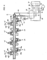
- variable valve timing mechanism VT and hydraulic control devices therefor will be explained in detail with reference to FIGS. 2 to 4 .
- the cylinder (not shown) is provided with an intake valve IV and an exhaust valve EV which are biased by valve springs 51 and 51 in a direction which closes an intake port (not shown) and an exhaust port (not shown), respectively.
- Reference symbol 52 indicates a lift cam provided on a camshaft 53.
- the lift cam 52 is engaged with an intake cam lifting rocker arm 54a for lifting the intake valve and an exhaust cam lifting rocker arm 54b for lifting the exhaust valve, both of which are rockably supported by the rocker shaft 31.
- the rocker shaft 31 also supports valve operating rocker arms 55a and 55b in a rockable manner, which are located adjacent to the cam lifting rocker arms 54a and 54b, and whose rocking ends press the top ends of the intake valve IV and the exhaust valve EV, respectively, so that the intake valve IV and the exhaust valve EV open their respective ports.
- the proximal ends (opposite the ends contacting the valves) of the valve operating rocker arms 55a and 55b are adapted to engage a circular cam 531 provided on the camshaft 53.
- FIGS. 3A and 3B show, as an example, the cam lifting rocker arm 54b and the valve operating rocker arm 55b associated with the exhaust valve EV.
- a hydraulic chamber 56 is formed in the cam lifting rocker arm 54b and the valve operating rocker arm 55b in a continuous manner, which is located on the opposite side of the rocker shaft 31 with respect to the lift cam 52.
- the hydraulic chamber 56 is provided with a pin 57a and a disengaging pin 57b, both of which are made slidable and are biased toward the cam lifting rocker arm 54b by means of a pin spring 58.
- the rocker shaft 31 is provided therein a hydraulic passage 59 which is divided into hydraulic passages 59a and 59b by a partition S.
- the hydraulic passage 59b is connected to the hydraulic chamber 56 at the position where the disengaging pin 57b is located via an opening 60b of the hydraulic passage 59b and a communication port 61b in the cam lifting rocker arm 54b.
- the hydraulic passage 59a is connected to the hydraulic chamber 56 at the position where the pin 57a is located via an opening 60a of the hydraulic passage 59a and a communication port 61a in the valve operating rocker arm 55b, and is adapted to be further connectable to a drain passage 38.
- the pin 57a is positioned by the pin spring 58 so as to bridge the cam lifting rocker arm 54b and the valve operating rocker arm 55b when oil pressure is not applied via the hydraulic passage 59b.
- both of the pin 57a and the disengaging pin 57b slide toward the valve operating rocker arm 55b against the biasing force of the pin spring 58, and the interface between the pin 57a and the disengaging pin 57b corresponds to the interface between the cam lifting rocker arm 54b and the valve operating rocker arm 55b so as to disconnect these rocker arms 54b and 55b, as shown in FIG. 3B .
- the intake valve side is constructed in a similar manner.
- the hydraulic passages 59a and 59b are connected to an oil pump 32 via the spool valves 33 and 33' which are provided for ensuring oil pressure of the variable valve timing mechanisms VT.
- a cylinder deactivation passage 34 is connected to the hydraulic passage 59b in the rocker shaft 31, and a cylinder activation passage 35 is connected to the hydraulic passage 59a.
- the spool valve 33' which is provided as a cylinder activation enforcing device, is disposed between the spool valve 33, which is provided as a lift amount changing device, and the variable valve timing mechanisms VT, which are provided as a lift operating device.
- a continuous cylinder activation which will be explained below in detail, is executed by operating the spool valve 33'.
- the spool valve 33 includes a casing 45 in which connection ports H1 to H4 are formed, and a spool 43 disposed inside the casing 45.
- a spool 43 In the surface of the spool 43 that faces the inner surface of the casing 45 in which connection ports H1 to H4 are formed, there are formed recesses, and the recesses and the inner surface of the casing 45 delimit ports P1 to P4.
- the ports P1 and P4 are connected to each other via a communication passage 44.
- the spool 43 is made slidable along the inner surface of the casing 45 in which connection ports H1 to H4 are formed using a solenoid (not shown).
- the spool valve 33' similarly to the spool valve 33, the spool valve 33' includes a casing 45' in which connection ports H1' to H6' are formed, and a spool 43' disposed inside the casing 45'. Recesses, which are formed in the spool 43', and the inner surface of the casing 45' of the spool 43' delimit ports P1' to P7'.
- the spool 43' is made slidable along the inner surface of the casing 45' using a solenoid (not shown).
- connection ports H1 to H4 of the spool valve 33 and the connection ports H1' to H6' of the spool valve 33' are connected to oil passages in which the operation oil flows, respectively. More specifically, the connection ports H1 to H4 are connected to a drain passage 38, a cylinder activation connection passage 42, an oil supply passage 36, and a cylinder deactivation connection passage 41, respectively.
- the connection ports H1' to H6' are connected to a drain branching passage 38' (a branching passage 38'), the cylinder deactivation passage 34, the cylinder deactivation connection passage 41, an oil supply branching passage 36' (a branching passage 36'), the cylinder activation passage 35, the cylinder activation connection passage 42, respectively.
- FIG. 5 is a diagram showing the flow of the operation oil in the all-cylinder activation mode.
- the spool valve 33 is controlled so that the drain passage 38 and the cylinder deactivation connection passage 41 are connected to each other via the ports P1 and P4, and the oil supply passage 36 and the cylinder activation connection passage 42 are connected to each other via the ports P2 and P3.
- the spool valve 33' is controlled so that the cylinder deactivation passage 34 and the cylinder deactivation connection passage 41 are connected to each other via the port P4', the cylinder activation connection passage 42 and the cylinder activation passage 35 are connected to each other via the port P7', and the branching passages 38' and 36' are closed by the ports P2' and P5'.
- the operation oil supplied from the oil pump 32 flows into the connection port H3 of the spool valve 33 via the oil supply passage 36, and then flows into the cylinder activation connection passage 42 via the port P3 and the connection port H2.
- the operation oil which flowed into the cylinder activation connection passage 42 flows into the connection port H6' in the spool valve 33', and flows into the cylinder activation passage 35 via the port P7' and the connection port H5', and thus the operation oil is supplied into the oil passage 59a in the rocker shaft 31.
- the branching passage 36' branching from the oil supply passage 36 is closed by the port P5'.
- the operation oil that has been held in the oil passage 59b in the rocker shaft 31 flows into the connection port H2' in the spool valve 33' via the cylinder deactivation passage 34, and then flows into the cylinder deactivation connection passage 41 via the port P4' and the connection port H3'.
- the operation oil which flowed into the cylinder deactivation connection passage 41 flows into the connection port H4 in the spool valve 33, and then flows into the drain passage 38 via the port P4, the communication passage 44, the port P1, and the connection port H1.
- the branching passage 38' branching from the drain passage 38 is closed by the port P2'.
- the operation oil is supplied into the hydraulic passage 59a for the all-cylinder activation operation provided in the rocker shaft 31, and the operation oil that has been held in the hydraulic passage 59b for the all-cylinder deactivation operation is released, and thus the all-cylinder activation operation is executed.
- FIG. 6 is a diagram showing the flow of the operation oil in the all-cylinder deactivation mode.
- the spool 43 of the spool valve 33 is moved downward when compared with the state shown in FIG. 5 .
- the spool valve 33 is controlled so that the drain passage 38 and the cylinder activation connection passage 42 are connected to each other via the ports P1 and P2, and the oil supply passage 36 and the cylinder deactivation connection passage 41 are connected to each other via the port P3.
- the operation oil supplied from the oil pump 32 flows into the connection port H3 of the spool valve 33 via the oil supply passage 36, and then flows into the cylinder deactivation connection passage 41 via the port P3 and the connection port H4.
- the operation oil which flowed into the cylinder deactivation connection passage 41 flows into the connection port H3' in the spool valve 33', and flows into the cylinder deactivation passage 34 via the port P4' and the connection port H2', and thus the operation oil is supplied into the oil passage 59b in the rocker shaft 31.
- the branching passage 36' branching from the oil supply passage 36 is closed by the port P5' as in the state shown in FIG. 5 .
- the operation oil that has been held in the oil passage 59a in the rocker shaft 31 flows into the connection port H5' in the spool valve 33' via the cylinder activation passage 35, and then flows into the cylinder activation connection passage 42 via the port P7' and the connection port H6'.
- the operation oil which flowed into the cylinder activation connection passage 42 flows into the connection port H2 in the spool valve 33, and then flows into the drain passage 38 via the port P1 and the connection port H1.
- the branching passage 38' branching from the drain passage 38 is closed by the port P2'.
- the operation oil is supplied into the hydraulic passage 59b for the all-cylinder deactivation operation provided in the rocker shaft 31, and the operation oil that has been held in the hydraulic passage 59a for the all-cylinder activation operation is released, and thus the all-cylinder deactivation operation is executed.
- FIG. 7 is a diagram showing the flow of the operation oil in the all-cylinder activation mode which is enforced by the spool valve 33' even though the spool valve 33 is switched into the all-cylinder deactivation mode.
- the spool 43' of the spool valve 33' is moved downward when compared with the state shown in FIG. 6 .
- the spool valve 33' is controlled so that the drain branching passage 38' and the cylinder deactivation passage 34 are connected to each other via the port P2', and drain branching passage 38' and the cylinder activation passage 35 are connected to each other via the port P5'.
- the cylinder deactivation passage 34 and the cylinder deactivation connection passage 41 are disconnected from each other by the port P4'.
- the cylinder activation connection passage 42 and the cylinder activation passage 35 are disconnected from each other by the port P7'.
- the operation oil supplied from the oil pump 32 flows into the connection port H4' of the spool valve 33' via the branching passage 36', and then flows into the cylinder activation passage 35 via the port P5' and the connection port H5', and thus the operation oil is supplied into the oil passage 59a in the rocker shaft 31.
- the operation oil that has been held in the oil passage 59b in the rocker shaft 31 flows into the connection port H2' in the spool valve 33' via the cylinder deactivation passage 34, and then flows into the drain branching passage 38' via the port P2' and the connection port H1'.
- the engine E can be reliably placed in or returned to the all-cylinder activation mode by operating the spool 43' of the spool valve 33'.
- connection or disconnection between the supply branching passage 36' and the cylinder activation passage 35, and the connection or disconnection between the drain branching passage 38' and the cylinder deactivation passage 34 can be executed by a single operation of the spool 43' of the spool valve 33'; therefore, a preferable efficiency in operation can be obtained.
- FIG. 8 is a plan view showing a spool valve 70' according to the second embodiment.
- FIG. 9A is a cross-sectional view showing the spool valve 70' in FIG. 8 taken along the line A-A
- FIG. 9B is a cross-sectional view showing the spool valve 70 in FIG. 8 taken along the line B-B.
- the same reference symbols are applied to the equivalent elements included in the first embodiment. As shown in FIGS.
- the spool valve 70' is provided with additional connection ports H7' and H8', and the spool valve 70' has two rows of connection ports arranged in the right-and-left direction in the drawings, each of which includes four connection ports.
- the spool valve 70' is provided with two spools 71' and 72' arranged in the right-and-left direction in the drawings.
- the spool 71' is made slidable to positions for making connection and disconnection between the drain branching passage 38' and the cylinder activation passage 35.
- the spool 72' is made slidable to positions for making connection and disconnection between the cylinder activation passage 35 and the supply branching passage 36'.
- the engine E can be reliably placed in or returned to the all-cylinder activation mode by operating the spools 71' and 72' of the spool valve 70' as shown in FIGS. 9A and 9B .
- the cylinder operation control apparatus of the present invention because the internal combustion engine can be reliably returned to the all-cylinder activation mode from a state in which all of the cylinders are deactivated, an all-cylinder deactivation operation, in which all of the cylinders are deactivated, may be executed; therefore, the engine friction can be greatly reduced, and thereby fuel economy can be improved.
- the engine friction can be further reduced, and thereby fuel economy can be further improved.
- the operation oil can be supplied to the cylinder activation passage so as to place the engine in the all-cylinder activation mode even when the engine is supposed to be placed in the cylinder deactivation mode in which the operation oil is supplied to the cylinder deactivation passage by the operation of the switching device. Therefore, the internal combustion engine can be reliably returned to the all-cylinder activation mode from a state in which all of the cylinders are deactivated, an all-cylinder deactivation operation, in which all of the cylinders are deactivated, may be executed. Accordingly, the engine friction can be greatly reduced, and thereby fuel economy can be improved.
- connection or disconnection between the supply branching passage and the cylinder activation passage, and the connection or disconnection between the drain branching passage and the cylinder deactivation passage can be executed by just a single operation; therefore, a preferable efficiency in operation can be obtained.
Landscapes
- Engineering & Computer Science (AREA)
- Mechanical Engineering (AREA)
- General Engineering & Computer Science (AREA)
- Valve Device For Special Equipments (AREA)
- Output Control And Ontrol Of Special Type Engine (AREA)
Claims (5)
- Regelungs-/ Steuerungsvorrichtung für einen Betrieb eines Zylinders, umfassend:einen Verbrennungsmotor (E), der dazu eingerichtet ist, in einem Sämtliche-Zylinder-Aktivierungsmodus, in welchem sämtliche Zylinder davon aktiviert sind, und in einem Zylinderdeaktivierungsmodus, in welchem all die Zylinder deaktiviert sind, zu arbeiten;eine Hubbetragsänderungsvorrichtung (VT), welche dem Verbrennungsmotor (E) zugeordnet ist und welche ein Umschalten zwischen dem Sämtliche-Zylinder-Aktivierungsmodus und dem Zylinderdeaktivierungsmodus ermöglicht durch Ändern des Hubbetrags von Einlass- und Auslassventilen (IV, EV), die den Zylindern zugeordnet sind, wobei die Hubbetragsänderungsvorrichtung (VT) einen hydraulischen Mechanismus für ein variables Ventil-Timing umfasst; undeine Hubbetätigungsvorrichtung (33), die der Hubbetragsänderungsvorrichtung (VT) zugeordnet ist, um dieselbe zu betreiben unter Verwendung eines von einer hydraulischen Leistungsquelle (32) zugeführten Betriebsöls;dadurch gekennzeichnet, dass eine Zylinderaktivierungserzwingungsvorrichtung (33'), die zwischen der Hubbetragsänderungsvorrichtung (VT) und der Hubbetätigungsvorrichtung (33) in Betrieb angeordnet ist, um, wenn notwendig, den Sämtliche-Zylinder-Aktivierungsmodus zu erzwingen; undeine Regelungs-/ Steuerungseinheit (11), die im Betrieb mit der Hubbetragsänderungsvorrichtung (VT), der Hubbetätigungsvorrichtung (33) und der Zylinderaktivierungserzwingungsvorrichtung (33') verbunden ist, um den Betriebsmodus des Verbrennungsmotors (E) zu regeln/steuern,wobei die Regelungs-/ Steuerungseinheit (11) die Zylinderaktivierungserzwingungsvorrichtung (33') betreibt, um Betriebsöl von der hydraulischen Leistungsquelle (32) der Hubbetragsänderungsvorrichtung (VT) zuzuführen, um, wenn notwendig, normalen Betriebe der Einlass- und Auslassventile (IV, EV) in dem Sämtliche-Zylinder-Aktivierungsmodus zu erzwingen, wenn die Hubbetätigungsvorrichtung (33) im Zylinderdeaktivierungsmodus gehalten ist aufgrund von Fehlerhaftigkeit.
- Regelungs-/ Steuerungsvorrichtung für einen Betrieb eines Zylinders nach Anspruch 1, wobei die Regelungs-/ Steuerungseinheit (11) den Öldruck für den hydraulischen Mechanismus für ein variables Ventil-Timing (VT) derart regelt/ steuert, dass die Betriebe der Einlass- und Auslassventile (IV, EV) ausgesetzt werden, wenn der Verbrennungsmotor (E) in den Zylinderdeaktivierungsmodus versetzt wird.
- Regelungs-/ Steuerungsvorrichtung für einen Betrieb eines Zylinders nach Anspruch 1, ferner umfassend:einen Zylinderaktivierungsdurchgang (35), der mit der Hubbetragsänderungsvorrichtung (VT) verbunden ist, um den Verbrennungsmotor (E) in den Sämtliche-Zylinder-Aktivierungsmodus zu überführen;einen Zylinderdeaktivierungsdurchgang (34), der mit der Hubbetragsänderungsvorrichtung (VT) verbunden ist, um den Verbrennungsmotor (E) in den Zylinderdeaktivierungsmodus zu versetzen;einen Ölzufuhrdurchgang (36), welcher mit dem Zylinderaktivierungsdurchgang (35) und dem Zylinderdeaktivierungsdurchgang (34) verbunden ist, um das Betriebsöl der Hubbetragsänderungsvorrichtung (VT) zuzuführen, und welcher mit einem Ölzufuhrabzweigungsdurchgang (36') versehen ist, der davon abzweigt;einen Abflussdurchgang (38), welcher mit dem Zylinderaktivierungsdurchgang (35) und dem Zylinderdeaktivierungsdurchgang (34) verbunden ist, um dem Betriebsöl zu ermöglichen, zurück in die hydraulische Leistungsquelle (32) zurückzukehren, und welcher über einen Abflussabzweigungsdurchgang (38') verfügt, der davon abzweigt;eine Umschaltvorrichtung (43), die mit dem Zylinderaktivierungsdurchgang (35), dem Zylinderdeaktivierungsdurchgang (34), dem Ölzufuhrdurchgang (36) und dem Abflussdurchgang (38) verbunden ist zum optionalen Zuführen des Betriebsöls von der hydraulischen Leistungsquelle zu dem Zylinderaktivierungsdurchgang (35) oder zu dem Zylinderdeaktivierungsdurchgang (34); undeine Zylinderaktivierungserzwingungsvorrichtung (33'), die mit dem Zylinderaktivierungsdurchgang (35), dem Zylinderdeaktivierungsdurchgang (34), dem Ölzufuhrabzweigungsdurchgang (36') und dem Abflussabzweigungsdurchgang (38') verbunden ist zum Erzwingen des Sämtliche-Zylinder-Aktivierungsmodus.
- Regelungs-/ Steuerungsvorrichtung für einen Betrieb eines Zylinders nach Anspruch 3, wobei die Zylinderaktivierungserzwingungsvorrichtung (33') umfasst: einen Zylinderaktivierungsanschluss (P5') für das optionale Verbinden des Ölzufuhrabzweigungsdurchgang (36') mit dem Zylinderaktivierungsdurchgang (35) oder das Trennen des Ölzufuhrabzweigungsdurchgangs (36') von dem Zylinderaktivierungsdurchgang (35); und einen Zylinderdeaktivierungsanschluss (P2') für das optionale Verbinden des Abflussabzweigungsdurchgangs (38') mit dem Zylinderdeaktivierungsdurchgang (34) oder das Trennen des Abflussabzweigungsdurchgangs (38') von dem Zylinderdeaktivierungsdurchgang (34).
- Regelungs-/ Steuerungsvorrichtung für einen Betrieb eines Zylinders nach Anspruch 4, wobei die Zylinderaktivierungserzwingungsvorrichtung (33') ein Steuerventil mit darin befindlicher Spule (43') umfasst, wobei das Steuerventil dazu eingerichtet ist, den Verbindungs- und Trennvorgang zwischen dem Ölzufuhrabzweigungsdurchgang (36') und dem Zylinderaktivierungsdurchgang (35), und den Verbindungs- und Trennvorgang zwischen dem Abflussabzweigungsdurchgang (38') und dem Zylinderdeaktivierungsdurchgang (34) durch Gleiten der Spule (43') in jeweilige vorgegebene Positionen durchzuführen.
Applications Claiming Priority (3)
| Application Number | Priority Date | Filing Date | Title |
|---|---|---|---|
| JP2002298595A JP4137584B2 (ja) | 2002-10-11 | 2002-10-11 | 内燃機関の気筒運転制御装置 |
| JP2002298595 | 2002-10-11 | ||
| PCT/JP2003/012331 WO2004033862A1 (en) | 2002-10-11 | 2003-09-26 | Cylinder operation control apparatus for internal combustion engine |
Publications (2)
| Publication Number | Publication Date |
|---|---|
| EP1549834A1 EP1549834A1 (de) | 2005-07-06 |
| EP1549834B1 true EP1549834B1 (de) | 2012-01-18 |
Family
ID=32089317
Family Applications (1)
| Application Number | Title | Priority Date | Filing Date |
|---|---|---|---|
| EP03807974A Expired - Lifetime EP1549834B1 (de) | 2002-10-11 | 2003-09-26 | Zylinderbetriebssteuervorrichtung für verbrennungsmotor |
Country Status (6)
| Country | Link |
|---|---|
| US (1) | US7040277B2 (de) |
| EP (1) | EP1549834B1 (de) |
| JP (1) | JP4137584B2 (de) |
| CN (1) | CN100390379C (de) |
| CA (1) | CA2501817C (de) |
| WO (1) | WO2004033862A1 (de) |
Families Citing this family (15)
| Publication number | Priority date | Publication date | Assignee | Title |
|---|---|---|---|---|
| US7819096B2 (en) * | 2007-10-30 | 2010-10-26 | Ford Global Technologies | Cylinder valve operating system for reciprocating internal combustion engine |
| US9689327B2 (en) | 2008-07-11 | 2017-06-27 | Tula Technology, Inc. | Multi-level skip fire |
| JP4702430B2 (ja) * | 2008-10-20 | 2011-06-15 | トヨタ自動車株式会社 | 内燃機関の可変動弁機構 |
| US8352156B2 (en) * | 2009-10-13 | 2013-01-08 | GM Global Technology Operations LLC | System and method for controlling engine components during cylinder deactivation |
| DE102013224921B4 (de) * | 2012-12-06 | 2023-05-17 | Ford Global Technologies, Llc | Verstellmagnetventilsteuerung |
| US9109487B2 (en) * | 2013-02-15 | 2015-08-18 | General Electric Company | Methods and system for cooling exhaust system components |
| US9399964B2 (en) | 2014-11-10 | 2016-07-26 | Tula Technology, Inc. | Multi-level skip fire |
| US10400691B2 (en) | 2013-10-09 | 2019-09-03 | Tula Technology, Inc. | Noise/vibration reduction control |
| US11236689B2 (en) | 2014-03-13 | 2022-02-01 | Tula Technology, Inc. | Skip fire valve control |
| US10662883B2 (en) | 2014-05-12 | 2020-05-26 | Tula Technology, Inc. | Internal combustion engine air charge control |
| US10233796B2 (en) * | 2014-05-12 | 2019-03-19 | Tula Technology, Inc. | Internal combustion engine using variable valve lift and skip fire control |
| KR101683492B1 (ko) * | 2014-12-09 | 2016-12-07 | 현대자동차 주식회사 | 실린더 휴지 엔진 |
| DE102015015087A1 (de) | 2015-11-20 | 2017-05-24 | Man Truck & Bus Ag | Variabler Ventiltrieb mit einem Kipphebel |
| US10493836B2 (en) | 2018-02-12 | 2019-12-03 | Tula Technology, Inc. | Noise/vibration control using variable spring absorber |
| CN114423932B (zh) | 2019-09-20 | 2024-10-18 | 卡明斯公司 | 机械定时气缸停用系统 |
Family Cites Families (7)
| Publication number | Priority date | Publication date | Assignee | Title |
|---|---|---|---|---|
| CN1004370B (zh) * | 1985-04-01 | 1989-05-31 | 本田技研工业株式会社 | 内燃机的泄压装置 |
| JPH0763097A (ja) | 1993-08-20 | 1995-03-07 | Mitsubishi Motors Corp | エンジンの燃料制御装置 |
| US6092497A (en) * | 1997-10-30 | 2000-07-25 | Eaton Corporation | Electromechanical latching rocker arm valve deactivator |
| US6382173B1 (en) * | 2000-05-02 | 2002-05-07 | Delphi Technologies, Inc. | Split body deactivation valve lifter |
| JP2002242717A (ja) | 2001-02-20 | 2002-08-28 | Honda Motor Co Ltd | ハイブリッド車両の制御装置 |
| JP3701567B2 (ja) * | 2001-02-20 | 2005-09-28 | 本田技研工業株式会社 | ハイブリッド車両の制御装置 |
| US6557518B1 (en) * | 2002-01-18 | 2003-05-06 | General Motors Corporation | Cylinder deactivation apparatus |
-
2002
- 2002-10-11 JP JP2002298595A patent/JP4137584B2/ja not_active Expired - Fee Related
-
2003
- 2003-09-26 CN CNB038239086A patent/CN100390379C/zh not_active Expired - Fee Related
- 2003-09-26 US US10/530,657 patent/US7040277B2/en not_active Expired - Fee Related
- 2003-09-26 WO PCT/JP2003/012331 patent/WO2004033862A1/en not_active Ceased
- 2003-09-26 CA CA002501817A patent/CA2501817C/en not_active Expired - Fee Related
- 2003-09-26 EP EP03807974A patent/EP1549834B1/de not_active Expired - Lifetime
Also Published As
| Publication number | Publication date |
|---|---|
| EP1549834A1 (de) | 2005-07-06 |
| WO2004033862A1 (en) | 2004-04-22 |
| JP4137584B2 (ja) | 2008-08-20 |
| CA2501817A1 (en) | 2004-04-22 |
| US20050284438A1 (en) | 2005-12-29 |
| CN100390379C (zh) | 2008-05-28 |
| CN1688798A (zh) | 2005-10-26 |
| JP2004132292A (ja) | 2004-04-30 |
| US7040277B2 (en) | 2006-05-09 |
| CA2501817C (en) | 2008-07-29 |
Similar Documents
| Publication | Publication Date | Title |
|---|---|---|
| EP1549834B1 (de) | Zylinderbetriebssteuervorrichtung für verbrennungsmotor | |
| KR100614188B1 (ko) | 감속 휴통 엔진 차량에서의 고장 검지장치 | |
| US8033954B2 (en) | Hybrid powertrain with reversing engine and method of control | |
| CA2460470C (en) | Motor control device for vehicle having deceleration deactivatable engine | |
| US6939263B2 (en) | Control device for hybrid vehicle | |
| CA2367223C (en) | Control apparatus for hybrid vehicle | |
| EP1365115B1 (de) | Hydraulische Ventilensteuereinheit in einer Brennkraftmaschine | |
| US20110088642A1 (en) | Valve train system of internal combustion engine | |
| US20020115526A1 (en) | Control apparatus for hybrid vehicle | |
| EP1319819B1 (de) | Verfahren zur Fehlererkennung in einem Hybridfahrzeug | |
| JP4202166B2 (ja) | 多気筒エンジン | |
| US8521397B2 (en) | Hybrid drive having valve deactivation | |
| JP3607261B2 (ja) | ハイブリッド車両における動弁機構の油圧供給装置 | |
| US20040226524A1 (en) | Direct acting differential two-step valve train | |
| CN1327115C (zh) | 内燃机带停缸机构的阀动装置 | |
| JP3917015B2 (ja) | 動弁機構の油圧制御装置 | |
| JP4011514B2 (ja) | 内燃機関の気筒運転制御装置 | |
| JP4508139B2 (ja) | 内燃機関の可変動弁装置 | |
| WO2008073357A2 (en) | Valve actuation system and method of driving two slave pistons with one master piston | |
| CN101560920B (zh) | 用于改进发动机效率的大重叠凸轮轴 | |
| JP3769783B2 (ja) | エンジンの動弁装置 | |
| JP2007262989A (ja) | 内燃機関の可変動弁装置 |
Legal Events
| Date | Code | Title | Description |
|---|---|---|---|
| PUAI | Public reference made under article 153(3) epc to a published international application that has entered the european phase |
Free format text: ORIGINAL CODE: 0009012 |
|
| 17P | Request for examination filed |
Effective date: 20050405 |
|
| AK | Designated contracting states |
Kind code of ref document: A1 Designated state(s): AT BE BG CH CY CZ DE DK EE ES FI FR GB GR HU IE IT LI LU MC NL PT RO SE SI SK TR |
|
| RBV | Designated contracting states (corrected) |
Designated state(s): DE FR GB |
|
| 17Q | First examination report despatched |
Effective date: 20100105 |
|
| GRAP | Despatch of communication of intention to grant a patent |
Free format text: ORIGINAL CODE: EPIDOSNIGR1 |
|
| GRAS | Grant fee paid |
Free format text: ORIGINAL CODE: EPIDOSNIGR3 |
|
| GRAA | (expected) grant |
Free format text: ORIGINAL CODE: 0009210 |
|
| AK | Designated contracting states |
Kind code of ref document: B1 Designated state(s): DE FR GB |
|
| RAP1 | Party data changed (applicant data changed or rights of an application transferred) |
Owner name: HONDA GIKEN KOGYO KABUSHIKI KAISHA |
|
| REG | Reference to a national code |
Ref country code: GB Ref legal event code: FG4D |
|
| RIN1 | Information on inventor provided before grant (corrected) |
Inventor name: HASEBE, TETSUYA Inventor name: KURODA, SHIGETAKA Inventor name: SUGIYAMA, TETSU |
|
| REG | Reference to a national code |
Ref country code: DE Ref legal event code: R096 Ref document number: 60339788 Country of ref document: DE Effective date: 20120315 |
|
| PLBE | No opposition filed within time limit |
Free format text: ORIGINAL CODE: 0009261 |
|
| STAA | Information on the status of an ep patent application or granted ep patent |
Free format text: STATUS: NO OPPOSITION FILED WITHIN TIME LIMIT |
|
| 26N | No opposition filed |
Effective date: 20121019 |
|
| PGFP | Annual fee paid to national office [announced via postgrant information from national office to epo] |
Ref country code: DE Payment date: 20120713 Year of fee payment: 10 |
|
| REG | Reference to a national code |
Ref country code: DE Ref legal event code: R097 Ref document number: 60339788 Country of ref document: DE Effective date: 20121019 |
|
| GBPC | Gb: european patent ceased through non-payment of renewal fee |
Effective date: 20120926 |
|
| REG | Reference to a national code |
Ref country code: FR Ref legal event code: ST Effective date: 20130531 |
|
| PG25 | Lapsed in a contracting state [announced via postgrant information from national office to epo] |
Ref country code: GB Free format text: LAPSE BECAUSE OF NON-PAYMENT OF DUE FEES Effective date: 20120926 |
|
| PG25 | Lapsed in a contracting state [announced via postgrant information from national office to epo] |
Ref country code: FR Free format text: LAPSE BECAUSE OF NON-PAYMENT OF DUE FEES Effective date: 20121001 |
|
| REG | Reference to a national code |
Ref country code: DE Ref legal event code: R119 Ref document number: 60339788 Country of ref document: DE Effective date: 20140401 |
|
| PG25 | Lapsed in a contracting state [announced via postgrant information from national office to epo] |
Ref country code: DE Free format text: LAPSE BECAUSE OF NON-PAYMENT OF DUE FEES Effective date: 20140401 |