EP1549426B2 - Verfahren und Vorrichtungssystem zur Abtrennung von schwerflüchtigen Komponenten aus einem Verdünnungsmittel, das in einen Suspensionspolymerisationsreaktor zurückgeführt wird - Google Patents
Verfahren und Vorrichtungssystem zur Abtrennung von schwerflüchtigen Komponenten aus einem Verdünnungsmittel, das in einen Suspensionspolymerisationsreaktor zurückgeführt wird Download PDFInfo
- Publication number
- EP1549426B2 EP1549426B2 EP03754708.0A EP03754708A EP1549426B2 EP 1549426 B2 EP1549426 B2 EP 1549426B2 EP 03754708 A EP03754708 A EP 03754708A EP 1549426 B2 EP1549426 B2 EP 1549426B2
- Authority
- EP
- European Patent Office
- Prior art keywords
- vapor
- diluent
- heavies
- liquid
- condenser
- Prior art date
- Legal status (The legal status is an assumption and is not a legal conclusion. Google has not performed a legal analysis and makes no representation as to the accuracy of the status listed.)
- Expired - Lifetime
Links
- 239000003085 diluting agent Substances 0.000 title claims description 98
- 239000002002 slurry Substances 0.000 title claims description 48
- 238000006116 polymerization reaction Methods 0.000 title claims description 36
- 238000000034 method Methods 0.000 title description 23
- 230000008569 process Effects 0.000 title description 19
- 239000007788 liquid Substances 0.000 claims description 156
- 229920000642 polymer Polymers 0.000 claims description 19
- 239000007787 solid Substances 0.000 claims description 19
- 239000012530 fluid Substances 0.000 claims description 15
- 239000002245 particle Substances 0.000 claims description 15
- 238000010926 purge Methods 0.000 claims description 12
- 238000000746 purification Methods 0.000 claims description 12
- 238000004891 communication Methods 0.000 claims description 9
- 238000011084 recovery Methods 0.000 claims description 9
- 239000007789 gas Substances 0.000 description 39
- IJGRMHOSHXDMSA-UHFFFAOYSA-N Atomic nitrogen Chemical compound N#N IJGRMHOSHXDMSA-UHFFFAOYSA-N 0.000 description 19
- 239000003054 catalyst Substances 0.000 description 19
- NNPPMTNAJDCUHE-UHFFFAOYSA-N isobutane Chemical compound CC(C)C NNPPMTNAJDCUHE-UHFFFAOYSA-N 0.000 description 16
- 239000000178 monomer Substances 0.000 description 15
- VLKZOEOYAKHREP-UHFFFAOYSA-N n-Hexane Chemical compound CCCCCC VLKZOEOYAKHREP-UHFFFAOYSA-N 0.000 description 11
- 230000003068 static effect Effects 0.000 description 11
- 238000005194 fractionation Methods 0.000 description 10
- 229930195733 hydrocarbon Natural products 0.000 description 10
- 150000002430 hydrocarbons Chemical class 0.000 description 10
- 239000013067 intermediate product Substances 0.000 description 10
- 150000001336 alkenes Chemical class 0.000 description 9
- 150000001875 compounds Chemical class 0.000 description 9
- 239000000203 mixture Substances 0.000 description 9
- 229910052757 nitrogen Inorganic materials 0.000 description 9
- 239000001282 iso-butane Substances 0.000 description 8
- JRZJOMJEPLMPRA-UHFFFAOYSA-N olefin Natural products CCCCCCCC=C JRZJOMJEPLMPRA-UHFFFAOYSA-N 0.000 description 8
- 238000004064 recycling Methods 0.000 description 7
- LIKMAJRDDDTEIG-UHFFFAOYSA-N 1-hexene Chemical compound CCCCC=C LIKMAJRDDDTEIG-UHFFFAOYSA-N 0.000 description 6
- VGGSQFUCUMXWEO-UHFFFAOYSA-N Ethene Chemical compound C=C VGGSQFUCUMXWEO-UHFFFAOYSA-N 0.000 description 5
- 239000005977 Ethylene Substances 0.000 description 5
- 230000007423 decrease Effects 0.000 description 5
- 238000006243 chemical reaction Methods 0.000 description 4
- 239000012263 liquid product Substances 0.000 description 4
- 208000033830 Hot Flashes Diseases 0.000 description 3
- 206010060800 Hot flush Diseases 0.000 description 3
- 230000008859 change Effects 0.000 description 3
- 238000002156 mixing Methods 0.000 description 3
- 239000000047 product Substances 0.000 description 3
- AFFLGGQVNFXPEV-UHFFFAOYSA-N 1-decene Chemical compound CCCCCCCCC=C AFFLGGQVNFXPEV-UHFFFAOYSA-N 0.000 description 2
- KWKAKUADMBZCLK-UHFFFAOYSA-N 1-octene Chemical compound CCCCCCC=C KWKAKUADMBZCLK-UHFFFAOYSA-N 0.000 description 2
- OFBQJSOFQDEBGM-UHFFFAOYSA-N Pentane Chemical compound CCCCC OFBQJSOFQDEBGM-UHFFFAOYSA-N 0.000 description 2
- 239000004698 Polyethylene Substances 0.000 description 2
- ATUOYWHBWRKTHZ-UHFFFAOYSA-N Propane Chemical compound CCC ATUOYWHBWRKTHZ-UHFFFAOYSA-N 0.000 description 2
- VYPSYNLAJGMNEJ-UHFFFAOYSA-N Silicium dioxide Chemical compound O=[Si]=O VYPSYNLAJGMNEJ-UHFFFAOYSA-N 0.000 description 2
- 125000004432 carbon atom Chemical group C* 0.000 description 2
- 239000012141 concentrate Substances 0.000 description 2
- 238000013461 design Methods 0.000 description 2
- 239000003701 inert diluent Substances 0.000 description 2
- TVMXDCGIABBOFY-UHFFFAOYSA-N n-Octanol Natural products CCCCCCCC TVMXDCGIABBOFY-UHFFFAOYSA-N 0.000 description 2
- CRSOQBOWXPBRES-UHFFFAOYSA-N neopentane Chemical compound CC(C)(C)C CRSOQBOWXPBRES-UHFFFAOYSA-N 0.000 description 2
- YWAKXRMUMFPDSH-UHFFFAOYSA-N pentene Chemical compound CCCC=C YWAKXRMUMFPDSH-UHFFFAOYSA-N 0.000 description 2
- -1 polyethylene Polymers 0.000 description 2
- 229920000573 polyethylene Polymers 0.000 description 2
- 238000012545 processing Methods 0.000 description 2
- QQONPFPTGQHPMA-UHFFFAOYSA-N propylene Natural products CC=C QQONPFPTGQHPMA-UHFFFAOYSA-N 0.000 description 2
- 125000004805 propylene group Chemical group [H]C([H])([H])C([H])([*:1])C([H])([H])[*:2] 0.000 description 2
- 238000000926 separation method Methods 0.000 description 2
- 238000012546 transfer Methods 0.000 description 2
- 238000011144 upstream manufacturing Methods 0.000 description 2
- VXNZUUAINFGPBY-UHFFFAOYSA-N 1-Butene Chemical compound CCC=C VXNZUUAINFGPBY-UHFFFAOYSA-N 0.000 description 1
- OTMSDBZUPAUEDD-UHFFFAOYSA-N Ethane Chemical compound CC OTMSDBZUPAUEDD-UHFFFAOYSA-N 0.000 description 1
- WGLPBDUCMAPZCE-UHFFFAOYSA-N Trioxochromium Chemical compound O=[Cr](=O)=O WGLPBDUCMAPZCE-UHFFFAOYSA-N 0.000 description 1
- 230000002159 abnormal effect Effects 0.000 description 1
- 230000008901 benefit Effects 0.000 description 1
- 230000015572 biosynthetic process Effects 0.000 description 1
- IAQRGUVFOMOMEM-UHFFFAOYSA-N butene Natural products CC=CC IAQRGUVFOMOMEM-UHFFFAOYSA-N 0.000 description 1
- 229910000423 chromium oxide Inorganic materials 0.000 description 1
- 230000006835 compression Effects 0.000 description 1
- 238000007906 compression Methods 0.000 description 1
- 238000009833 condensation Methods 0.000 description 1
- 230000005494 condensation Effects 0.000 description 1
- 239000000356 contaminant Substances 0.000 description 1
- 238000007334 copolymerization reaction Methods 0.000 description 1
- 230000003247 decreasing effect Effects 0.000 description 1
- 229910001873 dinitrogen Inorganic materials 0.000 description 1
- 238000007599 discharging Methods 0.000 description 1
- 238000011143 downstream manufacturing Methods 0.000 description 1
- 238000001035 drying Methods 0.000 description 1
- 239000000284 extract Substances 0.000 description 1
- 238000001914 filtration Methods 0.000 description 1
- 238000010438 heat treatment Methods 0.000 description 1
- QWTDNUCVQCZILF-UHFFFAOYSA-N iso-pentane Natural products CCC(C)C QWTDNUCVQCZILF-UHFFFAOYSA-N 0.000 description 1
- 239000007791 liquid phase Substances 0.000 description 1
- 238000004519 manufacturing process Methods 0.000 description 1
- 239000000463 material Substances 0.000 description 1
- 239000012968 metallocene catalyst Substances 0.000 description 1
- IJDNQMDRQITEOD-UHFFFAOYSA-N n-butane Chemical compound CCCC IJDNQMDRQITEOD-UHFFFAOYSA-N 0.000 description 1
- JTJMJGYZQZDUJJ-UHFFFAOYSA-N phencyclidine Chemical class C1CCCCN1C1(C=2C=CC=CC=2)CCCCC1 JTJMJGYZQZDUJJ-UHFFFAOYSA-N 0.000 description 1
- 229920000098 polyolefin Polymers 0.000 description 1
- 238000002360 preparation method Methods 0.000 description 1
- 239000001294 propane Substances 0.000 description 1
- 239000011347 resin Substances 0.000 description 1
- 229920005989 resin Polymers 0.000 description 1
- 230000011664 signaling Effects 0.000 description 1
- 239000000377 silicon dioxide Substances 0.000 description 1
- 238000003860 storage Methods 0.000 description 1
- 230000007704 transition Effects 0.000 description 1
- 239000012808 vapor phase Substances 0.000 description 1
- 230000008016 vaporization Effects 0.000 description 1
- XLYOFNOQVPJJNP-UHFFFAOYSA-N water Substances O XLYOFNOQVPJJNP-UHFFFAOYSA-N 0.000 description 1
Images
Classifications
-
- C—CHEMISTRY; METALLURGY
- C08—ORGANIC MACROMOLECULAR COMPOUNDS; THEIR PREPARATION OR CHEMICAL WORKING-UP; COMPOSITIONS BASED THEREON
- C08F—MACROMOLECULAR COMPOUNDS OBTAINED BY REACTIONS ONLY INVOLVING CARBON-TO-CARBON UNSATURATED BONDS
- C08F6/00—Post-polymerisation treatments
- C08F6/001—Removal of residual monomers by physical means
- C08F6/003—Removal of residual monomers by physical means from polymer solutions, suspensions, dispersions or emulsions without recovery of the polymer therefrom
-
- B—PERFORMING OPERATIONS; TRANSPORTING
- B01—PHYSICAL OR CHEMICAL PROCESSES OR APPARATUS IN GENERAL
- B01J—CHEMICAL OR PHYSICAL PROCESSES, e.g. CATALYSIS OR COLLOID CHEMISTRY; THEIR RELEVANT APPARATUS
- B01J19/00—Chemical, physical or physico-chemical processes in general; Their relevant apparatus
- B01J19/18—Stationary reactors having moving elements inside
- B01J19/1812—Tubular reactors
- B01J19/1837—Loop-type reactors
-
- B—PERFORMING OPERATIONS; TRANSPORTING
- B01—PHYSICAL OR CHEMICAL PROCESSES OR APPARATUS IN GENERAL
- B01J—CHEMICAL OR PHYSICAL PROCESSES, e.g. CATALYSIS OR COLLOID CHEMISTRY; THEIR RELEVANT APPARATUS
- B01J8/00—Chemical or physical processes in general, conducted in the presence of fluids and solid particles; Apparatus for such processes
- B01J8/0015—Feeding of the particles in the reactor; Evacuation of the particles out of the reactor
-
- B—PERFORMING OPERATIONS; TRANSPORTING
- B01—PHYSICAL OR CHEMICAL PROCESSES OR APPARATUS IN GENERAL
- B01J—CHEMICAL OR PHYSICAL PROCESSES, e.g. CATALYSIS OR COLLOID CHEMISTRY; THEIR RELEVANT APPARATUS
- B01J8/00—Chemical or physical processes in general, conducted in the presence of fluids and solid particles; Apparatus for such processes
- B01J8/18—Chemical or physical processes in general, conducted in the presence of fluids and solid particles; Apparatus for such processes with fluidised particles
- B01J8/20—Chemical or physical processes in general, conducted in the presence of fluids and solid particles; Apparatus for such processes with fluidised particles with liquid as a fluidising medium
- B01J8/22—Chemical or physical processes in general, conducted in the presence of fluids and solid particles; Apparatus for such processes with fluidised particles with liquid as a fluidising medium gas being introduced into the liquid
- B01J8/222—Chemical or physical processes in general, conducted in the presence of fluids and solid particles; Apparatus for such processes with fluidised particles with liquid as a fluidising medium gas being introduced into the liquid in the presence of a rotating device only
-
- C—CHEMISTRY; METALLURGY
- C08—ORGANIC MACROMOLECULAR COMPOUNDS; THEIR PREPARATION OR CHEMICAL WORKING-UP; COMPOSITIONS BASED THEREON
- C08F—MACROMOLECULAR COMPOUNDS OBTAINED BY REACTIONS ONLY INVOLVING CARBON-TO-CARBON UNSATURATED BONDS
- C08F10/00—Homopolymers and copolymers of unsaturated aliphatic hydrocarbons having only one carbon-to-carbon double bond
- C08F10/02—Ethene
-
- B—PERFORMING OPERATIONS; TRANSPORTING
- B01—PHYSICAL OR CHEMICAL PROCESSES OR APPARATUS IN GENERAL
- B01J—CHEMICAL OR PHYSICAL PROCESSES, e.g. CATALYSIS OR COLLOID CHEMISTRY; THEIR RELEVANT APPARATUS
- B01J2208/00—Processes carried out in the presence of solid particles; Reactors therefor
- B01J2208/00008—Controlling the process
- B01J2208/00017—Controlling the temperature
- B01J2208/00106—Controlling the temperature by indirect heat exchange
- B01J2208/00168—Controlling the temperature by indirect heat exchange with heat exchange elements outside the bed of solid particles
- B01J2208/00176—Controlling the temperature by indirect heat exchange with heat exchange elements outside the bed of solid particles outside the reactor
-
- B—PERFORMING OPERATIONS; TRANSPORTING
- B01—PHYSICAL OR CHEMICAL PROCESSES OR APPARATUS IN GENERAL
- B01J—CHEMICAL OR PHYSICAL PROCESSES, e.g. CATALYSIS OR COLLOID CHEMISTRY; THEIR RELEVANT APPARATUS
- B01J2208/00—Processes carried out in the presence of solid particles; Reactors therefor
- B01J2208/00008—Controlling the process
- B01J2208/00017—Controlling the temperature
- B01J2208/00106—Controlling the temperature by indirect heat exchange
- B01J2208/00168—Controlling the temperature by indirect heat exchange with heat exchange elements outside the bed of solid particles
- B01J2208/00212—Plates; Jackets; Cylinders
-
- B—PERFORMING OPERATIONS; TRANSPORTING
- B01—PHYSICAL OR CHEMICAL PROCESSES OR APPARATUS IN GENERAL
- B01J—CHEMICAL OR PHYSICAL PROCESSES, e.g. CATALYSIS OR COLLOID CHEMISTRY; THEIR RELEVANT APPARATUS
- B01J2208/00—Processes carried out in the presence of solid particles; Reactors therefor
- B01J2208/00008—Controlling the process
- B01J2208/00017—Controlling the temperature
- B01J2208/00106—Controlling the temperature by indirect heat exchange
- B01J2208/00265—Part of all of the reactants being heated or cooled outside the reactor while recycling
- B01J2208/00274—Part of all of the reactants being heated or cooled outside the reactor while recycling involving reactant vapours
-
- B—PERFORMING OPERATIONS; TRANSPORTING
- B01—PHYSICAL OR CHEMICAL PROCESSES OR APPARATUS IN GENERAL
- B01J—CHEMICAL OR PHYSICAL PROCESSES, e.g. CATALYSIS OR COLLOID CHEMISTRY; THEIR RELEVANT APPARATUS
- B01J2208/00—Processes carried out in the presence of solid particles; Reactors therefor
- B01J2208/00796—Details of the reactor or of the particulate material
- B01J2208/00823—Mixing elements
- B01J2208/00858—Moving elements
- B01J2208/00876—Moving elements outside the bed, e.g. rotary mixer
-
- B—PERFORMING OPERATIONS; TRANSPORTING
- B01—PHYSICAL OR CHEMICAL PROCESSES OR APPARATUS IN GENERAL
- B01J—CHEMICAL OR PHYSICAL PROCESSES, e.g. CATALYSIS OR COLLOID CHEMISTRY; THEIR RELEVANT APPARATUS
- B01J2219/00—Chemical, physical or physico-chemical processes in general; Their relevant apparatus
- B01J2219/00002—Chemical plants
- B01J2219/00004—Scale aspects
- B01J2219/00006—Large-scale industrial plants
-
- B—PERFORMING OPERATIONS; TRANSPORTING
- B01—PHYSICAL OR CHEMICAL PROCESSES OR APPARATUS IN GENERAL
- B01J—CHEMICAL OR PHYSICAL PROCESSES, e.g. CATALYSIS OR COLLOID CHEMISTRY; THEIR RELEVANT APPARATUS
- B01J2219/00—Chemical, physical or physico-chemical processes in general; Their relevant apparatus
- B01J2219/00049—Controlling or regulating processes
- B01J2219/00051—Controlling the temperature
- B01J2219/00074—Controlling the temperature by indirect heating or cooling employing heat exchange fluids
- B01J2219/00087—Controlling the temperature by indirect heating or cooling employing heat exchange fluids with heat exchange elements outside the reactor
- B01J2219/00094—Jackets
-
- B—PERFORMING OPERATIONS; TRANSPORTING
- B01—PHYSICAL OR CHEMICAL PROCESSES OR APPARATUS IN GENERAL
- B01J—CHEMICAL OR PHYSICAL PROCESSES, e.g. CATALYSIS OR COLLOID CHEMISTRY; THEIR RELEVANT APPARATUS
- B01J2219/00—Chemical, physical or physico-chemical processes in general; Their relevant apparatus
- B01J2219/00049—Controlling or regulating processes
- B01J2219/00191—Control algorithm
-
- B—PERFORMING OPERATIONS; TRANSPORTING
- B01—PHYSICAL OR CHEMICAL PROCESSES OR APPARATUS IN GENERAL
- B01J—CHEMICAL OR PHYSICAL PROCESSES, e.g. CATALYSIS OR COLLOID CHEMISTRY; THEIR RELEVANT APPARATUS
- B01J2219/00—Chemical, physical or physico-chemical processes in general; Their relevant apparatus
- B01J2219/00049—Controlling or regulating processes
- B01J2219/00245—Avoiding undesirable reactions or side-effects
- B01J2219/00252—Formation of deposits other than coke
-
- B—PERFORMING OPERATIONS; TRANSPORTING
- B01—PHYSICAL OR CHEMICAL PROCESSES OR APPARATUS IN GENERAL
- B01J—CHEMICAL OR PHYSICAL PROCESSES, e.g. CATALYSIS OR COLLOID CHEMISTRY; THEIR RELEVANT APPARATUS
- B01J2219/00—Chemical, physical or physico-chemical processes in general; Their relevant apparatus
- B01J2219/18—Details relating to the spatial orientation of the reactor
- B01J2219/182—Details relating to the spatial orientation of the reactor horizontal
-
- B—PERFORMING OPERATIONS; TRANSPORTING
- B01—PHYSICAL OR CHEMICAL PROCESSES OR APPARATUS IN GENERAL
- B01J—CHEMICAL OR PHYSICAL PROCESSES, e.g. CATALYSIS OR COLLOID CHEMISTRY; THEIR RELEVANT APPARATUS
- B01J2219/00—Chemical, physical or physico-chemical processes in general; Their relevant apparatus
- B01J2219/18—Details relating to the spatial orientation of the reactor
- B01J2219/185—Details relating to the spatial orientation of the reactor vertical
-
- C—CHEMISTRY; METALLURGY
- C08—ORGANIC MACROMOLECULAR COMPOUNDS; THEIR PREPARATION OR CHEMICAL WORKING-UP; COMPOSITIONS BASED THEREON
- C08F—MACROMOLECULAR COMPOUNDS OBTAINED BY REACTIONS ONLY INVOLVING CARBON-TO-CARBON UNSATURATED BONDS
- C08F110/00—Homopolymers of unsaturated aliphatic hydrocarbons having only one carbon-to-carbon double bond
- C08F110/02—Ethene
-
- C—CHEMISTRY; METALLURGY
- C08—ORGANIC MACROMOLECULAR COMPOUNDS; THEIR PREPARATION OR CHEMICAL WORKING-UP; COMPOSITIONS BASED THEREON
- C08F—MACROMOLECULAR COMPOUNDS OBTAINED BY REACTIONS ONLY INVOLVING CARBON-TO-CARBON UNSATURATED BONDS
- C08F210/00—Copolymers of unsaturated aliphatic hydrocarbons having only one carbon-to-carbon double bond
- C08F210/16—Copolymers of ethene with alpha-alkenes, e.g. EP rubbers
Definitions
- An efficient system and process of recycling diluent in a slurry polymerization process are desired. Further, an improved heavies removal system and process, which remove heavies from the diluent to be recycled to the reactor, are desired.
- a static mixer can be fluidly connected to and downstream from the first condenser, and the static mixer is upstream from and fluidly connected to the liquid collection tank.
- the static mixer is employed to quicken the formation of an equilibrium mixture after the hot flash gas and cold liquid are combined. It is desirable to have equilibrium conditions before entering the collection tank, at least a temperature equilibrium.
- a recycle tank may be disposed along the diluent recycle line downstream of the flash gas condenser.
- the liquid containing a higher concentration of the heavier components is passed from the liquid collection tank to a heavies delivery line, and the vapor is passed to a diluent recycle line.
- the vapor may be passed to a second condenser and a recycle surge tank.
- the vapor from the liquid collection tank can be condensed and recycled to the slurry polymerization reactor without further treatment to remove heavies.
- vapor comprising diluent, unreacted monomers/comonomers and various inerts, both heavier and lighter than the primary diluent (for example, isobutane), are separated.
- Various other compounds associated with the feedstocks and diluent feed such as other compounds with 4 carbons (for example, n-butane) and compounds with six carbons (for example, n-hexane), are inerts, which do not polymerize and function as a diluent along with isobutane.
- Heavies include additional compounds with six carbons along with any heavier compounds that may be produced in the reactor (such as oligomers).
- Suitable diluents for use as the liquid medium are well known in the art and include hydrocarbons, which are inert and liquid under reaction conditions. Suitable hydrocarbons include isobutane, propane, n-pentane, i-pentane, neopentane and n-hexane, with isobutane being especially preferred. Additional details regarding loop reactor apparatus and polymerization processes may be found in U.S. Patent Nos. 4,674,290 ; 5,183,866 ; 5,455,314 ; 5,565,174 ; 5,624,877 ; 6,005,061 ; 6,045,661 ; 6,051,631 ; 6,114,501 ; 6,262,191 ; and 6,420,497 .
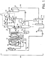
- FIG. 1 is a representation of a slurry polymerization system 10 according to the present invention.
- the slurry polymerization system 10 includes a catalyst feed tank 12 (such as a catalyst mudpot or an agitated tank) containing a mixture of catalyst and diluent. Catalyst and diluent from the catalyst tank 12 are pumped into a loop reactor 14.
- a catalyst feed tank 12 such as a catalyst mudpot or an agitated tank
- flashline heaters 16 also described as an intermediate pressure flash chamber
- flash gas separator also described as an intermediate pressure flash chamber
- heavies removal system 20 a fluff chamber 22
- purge column 24 a recycle treater 26
- isobutane/nitrogen recovery unit (INRU) 28 a recycle tank 30
- heavies column 32 a lights column 34
- olefin free surge unit 36 a series of conduits, pumps and condensers.
- flashing tends to occur as the intermediate product slurry passes across the continuous take-off device 52 and the flashline 54.
- the intermediate product slurry is heated in the flashline 54 to fully vaporize the diluent liquids so that the solids and vapors that discharge into the flash gas separator 18 are free of liquids.
- flashline 54 In some systems utilizing a flashline heater 16, some or all of the diluent (or other liquid medium) will flash in flashline 54 prior to introduction to the flash gas separator 18, which may be termed a "flash chamber” or an “intermediate pressure flash chamber.” These terms still are frequently used for the tank that follows the flashline, where vaporized diluent separates from polymer solids. "Flash tank” or “flash chamber” are still used even though there may be little or no flashing in the flash tank if all or substantially all of the diluent is vaporized in the flashline. In current designs that have the flashlines discharging at higher pressures and without downstream drying devices, it is intended to design the flashlines so there is little or no pressure drop on entering the flash tank, with essentially all of the liquids vaporized prior to entering the vessel.
- the fluff may pass to a second flash gas separator (for example, a low pressure flash chamber).
- a second flash gas separator for example, a low pressure flash chamber.
- a two-stage flash system is disclosed in U.S. Patent No. 4,424,341 .
- the fluff may pass from a bottom portion of the first flash chamber to the purge column 24. (The purge column 24 may follow the second flash chamber instead).
- the fluff may be passed through a conveyor dryer and then to a purge column as described in U.S. Patent No. 4,501,885 . Entrained diluent within the polymer particles is separated from the fluff in the purge column 24 by passing nitrogen gas through the solid polymer particles (the fluff).
- the nitrogen extracts entrained diluent and/or liquid diluent, thereby leaving solid polymer essentially free of entrained diluent.
- the solid polymer is then deposited, collected, ejected or otherwise withdrawn from a bottom portion of the purge column 24.
- the nitrogen and extracted diluent are then passed out a top portion of the purge column 24 to an isobutane/nitrogen recovery unit (INRU) 28.
- the INRU processes the vapors removed from the fluff in the purge column.
- the INRU separates the nitrogen from the diluent vapors by condensing the diluent vapors into liquids. In one sense the INRU functions somewhat like the heavies removal system by condensing a relatively small amount of the flash gas and sending a liquid to the heavies column.
- the INRU 28 separates nitrogen from diluent and other hydrocarbons. The nitrogen is then passed back to the purge column 24 through a nitrogen return line 60.
- the vapor removal line 56 may include a series of filters and components, such as bag filters, for filtering fine polymer particles from the vapor stream in order to prevent the fines from entering the heavies removal system 20.
- the vapor stream is primarily isobutane diluent, but the vapor stream diluent also contains heavies, such as 1-hexene co-monomers and other hydrocarbons having six or more carbon atoms.
- the vapor stream may also contain lighter hydrocarbons such as ethane and ethylene.
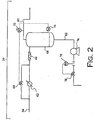
- FIG. 2 is a representation of an exemplary heavies removal system 20.
- the heavies removal system 20 is fluidly connected to, and communicates with, a top portion of the flash gas separator 18 through the vapor removal line 56.
- the heavies removal system 20 includes a first condenser 62, a bypass line 63, a bypass valve 64, a static mixer 66, a liquid collection tank 68, a temperature controller 70, a level controller 72, a pump 74, a flow controller 76 and a flow control valve 78.
- the heavies removal system 20 is designed and/or set so as to condense a small amount of liquid from the first vapor stream.
- a fraction of flash gas (in other words, a first portion of the first vapor stream) is passed through the condenser 62, which condenses some of that fraction into a liquid.
- the liquid from condenser 62 contacts the relatively hot flash gas that has bypassed the condenser 62 (in other words, a second portion of the first vapor stream)
- some of the liquid again vaporizes, leaving a residual amount of liquid and a larger amount of flash gas.
- the liquid and flash gas are passed to the liquid collection tank 68.
- the heavies removal system 20 produces liquid with a higher percentage of the heavier components than is found in the vapor stream.
- the liquid in the collection tank 68 may contain at least about 1%, alternatively at least about 5%, alternatively at least about 10%, of the heavies in the vapor stream.
- the heavies removal system is expected to be particularly effective in removing most oligomers, for example, at least about 2%, alternatively at least about 10%, alternatively about 20% of the oligomers in the vapor stream. Even if the heavies removal system does not remove all the heavies from the liquid medium to be recycled to the polymerization reactor, it still provides an important benefit by preventing an excessive buildup of heavies in the recycled medium.
- the bypass valve may be in informational communication with the level controller 72, which is positioned within the liquid collection tank 68.
- the temperature controller 70 and the level controller 72 may be assisted by or used in conjunction with a central processing unit or other logic unit or main controller.
- the temperature controller 70 and the level controller 72 relay signals to the bypass valve 64 to close or open the bypass line 63, depending on temperature and level conditions within the heavies removal system 20. This control scheme permits automatic control to obtain the desired amount of liquid in the liquid collection tank 68.
- the flow control valve 78 may be operated in conjunction with the flow controller 76. Depending on the rate of flow of heavies through the heavies delivery line 82, the flow controller 76 may send a command signal to the flow control valve 78 to open or close the heavies delivery line 82.
- the heavies removal system 20 is configured to produce liquids relatively concentrated in heavies that were contained within the first vapor stream. It is contemplated that at least some of the heavies from the first vapor stream, or a major portion thereof, will be passed to the heavies delivery line 82. For example, about 98% of the first vapor stream may remain as a vapor as a result of bypassing the first condenser, in other words only a small amount of liquids are generated. A portion of the first vapor stream is sent to the condenser where all or most of that portion is converted to liquid. This colder liquid is combined with the hotter gases that bypassed the condenser and this liquid and vapor mixture is sent to the static mixer 66. The static mixer ensures good mixing of the liquids and vapors so that substantially equilibrium conditions can quickly be generated.
- Substantially equilibrium conditions means that the liquid and vapor in the liquid collection tank come to substantially the same temperature with some of the liquids vaporizing to accomplish this.
- the gas may then be passed to collection tank where the liquids and vapors initially intermingle but also are separated. As flash gas condenses and re-evaporates, heavies are left behind in the liquid at the bottom of the collection tank.
- the amount of the first vapor stream that is diverted into the condenser 62 is controlled to generate a desired amount of liquids in the liquid collection tank 68.
- the bypassed hot vapor and condenser-cooled liquid from the condenser 62 are then mixed by the static mixer 66.
- the temperature controller 70 may signal the bypass valve 64 to open or close to a desired extent, depending on the temperature of the diluent vapor in the diluent recycle line 80.
- the mixture is passed into the liquid collection tank 68.
- the liquid collection tank 68 separates the liquids containing a higher concentration of the heavier components from the diluent vapor. It is desirable to reduce or avoid pressure or temperature gradients in the liquid collection tank.
- the temperature controller 70 can be periodically or occasionally reset by the level controller on the collection tank. If the level in the collection tank drops below the level setpoint, the controller sends a signal to lower the setpoint of the temperature controller which in turn sends a signal to close the bypass valve to a desired extent and force more flow through the condenser to generate more liquids. Conversely, if the level in the tank is above the desired setpoint, the level controller sends a signal to raise the setpoint of the temperature controller which in turns sends a signal to open the bypass valves to a desired extent which decreases the flow through the condenser which reduces the amount of liquids formed. When the setpoint of the flow controller is changed, the flow control valve opens or closes to produce the desired flow, and this change of flow is reflected as a change in level in the tank, and the level controller reacts to change the amount of liquids condensed.
- the liquid concentrated in heavies is passed from the liquid collection tank 68 through the heavies delivery line 82 and pumped towards the heavies column 32 by the pump 74.
- the flow controller 76 monitors and controls the flow of the liquid through the heavies delivery line 82 by signaling the flow control valve 78 to open or close the flow control valve 78, depending on the desired amount of liquids to be generated. For example, if the operators want to create 1500 kg/hr liquids, it is desirable that that number can be entered as a setpoint to the flow controller.
- the liquids are ultimately delivered to the heavies column 32.
- the heavies column 32 separates the liquid medium and lighter components from the heavies.
- the diluent (in other words, the liquid medium) extracted in the heavies column 32 is then passed to a lights column 34, where lights are removed, thereby yielding essentially or substantially pure diluent, which is then passed through the olefin-free surge 36 and pumped to the catalyst feed tank 12 or to the recycle tank 30, and it is then pumped to the loop reactor 14.
- the diluent vapor within the diluent recycle line 80 is passed through a flash gas condenser 84, which may condense, or liquefy, the diluent. Some diluent with a relatively high concentration of lighter components may remain as vapor.
- the stream is passed to the recycle tank 30, which serves as a vapor-liquid separation drum and the liquids are passed directly back to the loop reactor 14 through the recycle treater 26.
- the vapor which has a higher relative concentration of the lighter components is passed to fractionation where the light components are rejected, and 1-hexene and hexanes are recovered or rejected, octane and heavier compounds are rejected, and diluent (usually isobutane) is recovered free of olefins
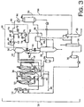
- FIG. 3 is a schematic representation of another slurry polymerization system 11, which includes a novel heavies removal system.
- the lights removal line 86 may be a vapor line that enters through the side of the heavies column 32. Since vapor line 86 will contain small amounts of hexane, it is desirable to have it enter the heavies column because all hexanes must be excluded from the lights column.
- the INRU is designed to recover both nitrogen and hydrocarbons (diluent) as liquid.
- the liquid product line 90 may be split with one branch connecting to the heavies column 32 and another branch connecting to the recycle tank 30.
- liquids may be directed to the heavies column 32 and/or to the recycle tank 30.
- the olefin-free product that is passed from the olefm-free surge unit 36 may be pumped back to the recycle tank 30 in addition to the catalyst mix tank 12.
- the direct recycle fractionators can be fed from a recycle liquid slip stream or by INRU liquid product but by creating liquids with the present heavies removal system, heavies concentration is controlled better, in other words for the same fractionation feed rate, heavies concentration in the recycle is lower.
- the present system and process described may also feed fractionation (heavies and lights columns) when the INRU is not operational so that olefin-free diluent may be generated to slurry the catalyst.
Landscapes
- Chemical & Material Sciences (AREA)
- Chemical Kinetics & Catalysis (AREA)
- Organic Chemistry (AREA)
- Health & Medical Sciences (AREA)
- Medicinal Chemistry (AREA)
- Polymers & Plastics (AREA)
- Dispersion Chemistry (AREA)
- Engineering & Computer Science (AREA)
- Combustion & Propulsion (AREA)
- Polymerisation Methods In General (AREA)
- Addition Polymer Or Copolymer, Post-Treatments, Or Chemical Modifications (AREA)
Claims (5)
- Rückgewinnungs- und Reinigungssystem für ein flüssiges Medium von einer Schlammpolymerisation, wobei das System Folgendes umfasst:einen ersten Fluidkanal, der an einem Ende mit einem Schlammpolymerisationsreaktor verbunden ist;einen Flashgasabscheider, der mit einem gegenüberliegenden Ende des ersten Fluidkanals verbunden ist, zum Abscheiden eines Dampfstroms, der feste Polymerpartikel in einem flüssigen Medium umfasst;eine Dampfentfernungsleitung, die an einem oberen Abschnitt des Flashgasabscheiders angeschlossen ist, zum Transportieren des Dampfstroms von dem Flashgasabscheider;einen ersten Kondensator stromabwärts von der Dampfentfernungsleitung;einen Auffangtank stromabwärts vom ersten Kondensator;eine Dampfumgehungsleitung zum Bereitstellen einer Umgehung für einen Teil des Dampfstroms um den Kondensator zum Auffangtank;ein Umgehungsventil zum Regeln des Flusses von Dampf durch die Dampfumgehungsleitung;eine Flüssigkeitszuführungsleitung in einem unteren Abschnitt des Auffangtanks;eine Dampfrezyklierungsleitung in einem oberen Abschnitt des Auffangtanks;einen zweiten Kondensator, der fluidisch mit der Dampfrezyklierungsleitung verbunden ist; undeinen zweiten Fluidkanal, der den Ausgang des zweiten Kondensators mit dem Schlammpolymerisationsreaktor verbindet,ferner umfassend eine Schwerteilesäule, die an einem gegenüberliegenden Ende der Flüssigkeitszuführungsleitung angeschlossen ist.
- Rückgewinnungs- und Reinigungssystem nach Anspruch 1, wobei das Umgehungsventil in Informationskommunikation mit einem Temperaturregler stromabwärts des Auffangtanks und/oder einem im Auffangtank positionierten Füllstandsregler ist.
- Rückgewinnungs- und Reinigungssystem nach Anspruch 2, wobei der Füllstandsregler in Informationskommunikation mit dem Temperaturregler ist und der Temperaturregler in Informationskommunikation mit dem Umgehungsventil ist.
- Rückgewinnungs- und Reinigungssystem nach Anspruch 1, das einen Rezyklierungstank umfasst, der entlang der Verdünnungsmittelrezyklierungsleitung stromabwärts vom zweiten Kondensator angeordnet ist.
- Rückgewinnungs- und Reinigungssystem nach Anspruch 1, das eine Spülsäule umfasst, die fluidisch zum Aufnehmen von festen Polymerpartikeln von dem Flashgasabscheider angeschlossen ist.
Applications Claiming Priority (5)
| Application Number | Priority Date | Filing Date | Title |
|---|---|---|---|
| US41125402P | 2002-09-16 | 2002-09-16 | |
| US411254P | 2002-09-16 | ||
| US10/662,249 US6818186B2 (en) | 2002-09-16 | 2003-09-15 | System for removing heavies from diluent recycled to a slurry polymerization reactor |
| PCT/US2003/029334 WO2004024311A1 (en) | 2002-09-16 | 2003-09-15 | Process and system for removing heavies from diluent recycled to a slurry polymerization reactor |
| US662249 | 2003-09-15 |
Publications (4)
| Publication Number | Publication Date |
|---|---|
| EP1549426A1 EP1549426A1 (de) | 2005-07-06 |
| EP1549426A4 EP1549426A4 (de) | 2009-06-03 |
| EP1549426B1 EP1549426B1 (de) | 2010-07-28 |
| EP1549426B2 true EP1549426B2 (de) | 2018-01-24 |
Family
ID=31998025
Family Applications (1)
| Application Number | Title | Priority Date | Filing Date |
|---|---|---|---|
| EP03754708.0A Expired - Lifetime EP1549426B2 (de) | 2002-09-16 | 2003-09-15 | Verfahren und Vorrichtungssystem zur Abtrennung von schwerflüchtigen Komponenten aus einem Verdünnungsmittel, das in einen Suspensionspolymerisationsreaktor zurückgeführt wird |
Country Status (8)
| Country | Link |
|---|---|
| US (2) | US6818186B2 (de) |
| EP (1) | EP1549426B2 (de) |
| AU (1) | AU2003272521A1 (de) |
| BR (1) | BRPI0314396B1 (de) |
| CA (1) | CA2498745C (de) |
| ES (1) | ES2349631T5 (de) |
| MX (1) | MXPA05002954A (de) |
| WO (1) | WO2004024311A1 (de) |
Cited By (1)
| Publication number | Priority date | Publication date | Assignee | Title |
|---|---|---|---|---|
| US12606648B2 (en) | 2023-07-13 | 2026-04-21 | Chevron Phillips Chemical Company Lp | Centralized hydrocarbon treatment in a polymer production process |
Families Citing this family (24)
| Publication number | Priority date | Publication date | Assignee | Title |
|---|---|---|---|---|
| US6994827B2 (en) * | 2000-06-03 | 2006-02-07 | Symyx Technologies, Inc. | Parallel semicontinuous or continuous reactors |
| US7524904B2 (en) * | 2002-09-16 | 2009-04-28 | Chevron Phillips Chemical Company Lp | Process and apparatus for separating polymer solids, hydrocarbon fluids, and purge gas |
| DE602004001391T2 (de) * | 2004-04-29 | 2007-05-31 | Borealis Technology Oy | Verfahren und Vorrichtung zur Herstellung von Olefinpolymeren |
| ES2416314T3 (es) | 2004-08-27 | 2013-07-31 | Chevron Phillips Chemical Company Lp | Procesos de producción de poliolefinas |
| GB0426057D0 (en) | 2004-11-26 | 2004-12-29 | Solvay | Chemical process |
| GB0426059D0 (en) * | 2004-11-26 | 2004-12-29 | Solvay | Chemical process |
| GB0426058D0 (en) * | 2004-11-26 | 2004-12-29 | Solvay | Chemical process |
| US7629421B2 (en) * | 2005-12-21 | 2009-12-08 | Chevron Phillips Chemical Company Lp | Monomer recovery by returning column overhead liquid to the reactor |
| EP1825910A1 (de) * | 2006-02-24 | 2007-08-29 | Total Petrochemicals Research Feluy | Methode zur Umwandlung eines Schleifenreaktors |
| US7957947B2 (en) | 2006-08-25 | 2011-06-07 | Chevron Phillips Chemical Company Lp | Method and apparatus for managing volatile organic content in polyolefin |
| EP1918308A1 (de) * | 2006-10-30 | 2008-05-07 | Total Petrochemicals Research Feluy | Verfahren zur Verbesserung der Entgasung von in einem Polymerisationsreaktor hergestellten Polymeraufschlämmungen |
| US7910689B2 (en) * | 2007-03-16 | 2011-03-22 | Exxonmobil Chemical Patents Inc. | Method and apparatus for separation of polymer from a slurry |
| US9211523B2 (en) | 2010-07-01 | 2015-12-15 | Chevron Phillips Chemical Company Lp | Polyolefin manufacturing system including a membrane fractionation system for diluent recovery |
| US8597582B2 (en) | 2011-06-30 | 2013-12-03 | Chevron Phillips Chemical Company Lp | Flashline heater system and method |
| US10792609B2 (en) | 2018-05-07 | 2020-10-06 | Chevron Phillips Chemical Company Lp | Nitrogen conservation in polymerization processes |
| CA3102557A1 (en) * | 2018-06-15 | 2019-12-19 | Dow Global Technologies Llc | Separations system for recovering hydrocarbons from synthesis of polyethylene polymers |
| WO2020163093A1 (en) | 2019-02-05 | 2020-08-13 | Exxonmobil Chemical Patents Inc. | Recycle diluent control and optimization for slurry loop polyethylene reactors |
| US11021549B2 (en) | 2019-05-06 | 2021-06-01 | Chevron Phillips Chemical Company, Lp | System and method for rapid dump tank heating |
| JP7210778B2 (ja) | 2019-05-29 | 2023-01-23 | バーゼル・ポリオレフィン・ゲーエムベーハー | ポリマー粒子の乾燥を含むエチレンポリマーの製造のための懸濁方法 |
| US11813583B2 (en) | 2019-09-13 | 2023-11-14 | Exxonmobil Chemical Patents Inc. | Slurry loop reactor bad catalyst range control |
| WO2021050229A1 (en) | 2019-09-13 | 2021-03-18 | Exxonmobil Chemical Patents Inc. | Vent gas purge optimizer for slurry loop polyethylene reactors |
| ES3017033T3 (en) * | 2020-08-13 | 2025-05-12 | Borealis Ag | Process for screening polymer from an effluent stream at reduced levels of polymer entrainment |
| CN114195913B (zh) * | 2021-12-23 | 2023-08-18 | 广东鲁众华新材料有限公司 | 一种提高碳五石油树脂闪蒸效果的方法 |
| US12025351B2 (en) * | 2022-06-08 | 2024-07-02 | Chevron Phillips Chemical Company Lp | Geothermal cooling of a coolant used in a heat exchange equipment |
Citations (3)
| Publication number | Priority date | Publication date | Assignee | Title |
|---|---|---|---|---|
| US3816379A (en) † | 1971-07-26 | 1974-06-11 | Exxon Research Engineering Co | Monomer and solvent recovery in polymerization processes |
| US6045661A (en) † | 1998-05-20 | 2000-04-04 | Phillips Petroleum Company | Process and apparatus for recovering diluent, monomer, and comonomer from a polymerization reactor effluent |
| US6262191B1 (en) † | 1999-03-09 | 2001-07-17 | Phillips Petroleum Company | Diluent slip stream to give catalyst wetting agent |
Family Cites Families (5)
| Publication number | Priority date | Publication date | Assignee | Title |
|---|---|---|---|---|
| LU34020A1 (de) | 1953-01-27 | 1956-02-06 | ||
| US4424341A (en) * | 1981-09-21 | 1984-01-03 | Phillips Petroleum Company | Separation of solid polymers and liquid diluent |
| US5455314A (en) | 1994-07-27 | 1995-10-03 | Phillips Petroleum Company | Method for controlling removal of polymerization reaction effluent |
| US6114400A (en) * | 1998-09-21 | 2000-09-05 | Air Products And Chemicals, Inc. | Synthesis gas production by mixed conducting membranes with integrated conversion into liquid products |
| US6559247B2 (en) | 1999-03-09 | 2003-05-06 | Chevron Phillips Chemical Company, Lp | Direct recycle fractionation method using a swing column |
-
2003
- 2003-09-15 EP EP03754708.0A patent/EP1549426B2/de not_active Expired - Lifetime
- 2003-09-15 US US10/662,249 patent/US6818186B2/en not_active Expired - Lifetime
- 2003-09-15 WO PCT/US2003/029334 patent/WO2004024311A1/en not_active Ceased
- 2003-09-15 MX MXPA05002954A patent/MXPA05002954A/es active IP Right Grant
- 2003-09-15 ES ES03754708.0T patent/ES2349631T5/es not_active Expired - Lifetime
- 2003-09-15 AU AU2003272521A patent/AU2003272521A1/en not_active Abandoned
- 2003-09-15 BR BRPI0314396-1A patent/BRPI0314396B1/pt not_active IP Right Cessation
- 2003-09-15 CA CA002498745A patent/CA2498745C/en not_active Expired - Lifetime
-
2004
- 2004-09-23 US US10/947,935 patent/US7087685B2/en not_active Expired - Lifetime
Patent Citations (3)
| Publication number | Priority date | Publication date | Assignee | Title |
|---|---|---|---|---|
| US3816379A (en) † | 1971-07-26 | 1974-06-11 | Exxon Research Engineering Co | Monomer and solvent recovery in polymerization processes |
| US6045661A (en) † | 1998-05-20 | 2000-04-04 | Phillips Petroleum Company | Process and apparatus for recovering diluent, monomer, and comonomer from a polymerization reactor effluent |
| US6262191B1 (en) † | 1999-03-09 | 2001-07-17 | Phillips Petroleum Company | Diluent slip stream to give catalyst wetting agent |
Non-Patent Citations (2)
| Title |
|---|
| KISTER H.Z.: "Distillation Operation", 1990, MC GRAW HILL, BOSTON, pages: 526 - 534 † |
| SCHNEIDER D.F. ET AL: "Practical process hydraulics considerations", HYDROCARBON PROCESSING, August 1999 (1999-08-01), pages 47 - 53 † |
Cited By (1)
| Publication number | Priority date | Publication date | Assignee | Title |
|---|---|---|---|---|
| US12606648B2 (en) | 2023-07-13 | 2026-04-21 | Chevron Phillips Chemical Company Lp | Centralized hydrocarbon treatment in a polymer production process |
Also Published As
| Publication number | Publication date |
|---|---|
| AU2003272521A1 (en) | 2004-04-30 |
| ES2349631T3 (es) | 2011-01-07 |
| BR0314396A (pt) | 2005-08-09 |
| US20040116626A1 (en) | 2004-06-17 |
| CA2498745C (en) | 2009-08-25 |
| EP1549426B1 (de) | 2010-07-28 |
| ES2349631T5 (es) | 2018-05-04 |
| MXPA05002954A (es) | 2005-10-19 |
| US6818186B2 (en) | 2004-11-16 |
| EP1549426A1 (de) | 2005-07-06 |
| US20050038207A1 (en) | 2005-02-17 |
| BRPI0314396B1 (pt) | 2015-09-01 |
| EP1549426A4 (de) | 2009-06-03 |
| WO2004024311A1 (en) | 2004-03-25 |
| US7087685B2 (en) | 2006-08-08 |
| CA2498745A1 (en) | 2004-03-25 |
Similar Documents
| Publication | Publication Date | Title |
|---|---|---|
| EP1549426B2 (de) | Verfahren und Vorrichtungssystem zur Abtrennung von schwerflüchtigen Komponenten aus einem Verdünnungsmittel, das in einen Suspensionspolymerisationsreaktor zurückgeführt wird | |
| KR100531628B1 (ko) | 연속적인 슬러리 중합반응의 휘발물질 제거 | |
| US7034090B2 (en) | Continuous slurry polymerization volatile removal | |
| CA2321825C (en) | Continuous slurry polymerization volatile removal | |
| US7524904B2 (en) | Process and apparatus for separating polymer solids, hydrocarbon fluids, and purge gas | |
| EP1165225B1 (de) | Verdünnungsseitenstrom zur erzeugung eines befeuchtungsmittels für katalysatoren | |
| US5575979A (en) | Process and apparatus for separating diluents from solid polymers utilizing a two-stage flash and a cyclone separator | |
| US6559247B2 (en) | Direct recycle fractionation method using a swing column | |
| AU755016B2 (en) | Continuous slurry polymerization volatile removal | |
| KR20040091644A (ko) | 루프 반응기를 사용하는 연속적인 슬러리 중합 방법 | |
| CN100402557C (zh) | 从循环到淤浆聚合反应器的稀释剂中脱除重组分的方法和体系 | |
| EP1344563B1 (de) | Kontinuierliches Entfernen flüchtiger Bestandteile aus Suspensionspolymerisation | |
| HK1048614B (en) | Diluent slip stream to give catalyst wetting agent | |
| KR20070018960A (ko) | 올레핀 중합체를 제조하는 방법 및 장치 |
Legal Events
| Date | Code | Title | Description |
|---|---|---|---|
| PUAI | Public reference made under article 153(3) epc to a published international application that has entered the european phase |
Free format text: ORIGINAL CODE: 0009012 |
|
| 17P | Request for examination filed |
Effective date: 20050418 |
|
| AK | Designated contracting states |
Kind code of ref document: A1 Designated state(s): AT BE BG CH CY CZ DE DK EE ES FI FR GB GR HU IE IT LI LU MC NL PT RO SE SI SK TR |
|
| AX | Request for extension of the european patent |
Extension state: AL LT LV MK |
|
| DAX | Request for extension of the european patent (deleted) | ||
| A4 | Supplementary search report drawn up and despatched |
Effective date: 20090504 |
|
| RIC1 | Information provided on ipc code assigned before grant |
Ipc: C08F 2/01 20060101ALI20090424BHEP Ipc: B01J 8/00 20060101AFI20040331BHEP Ipc: C08F 10/02 20060101ALN20090424BHEP Ipc: C08F 6/10 20060101ALI20090424BHEP |
|
| 17Q | First examination report despatched |
Effective date: 20090907 |
|
| GRAP | Despatch of communication of intention to grant a patent |
Free format text: ORIGINAL CODE: EPIDOSNIGR1 |
|
| GRAS | Grant fee paid |
Free format text: ORIGINAL CODE: EPIDOSNIGR3 |
|
| GRAA | (expected) grant |
Free format text: ORIGINAL CODE: 0009210 |
|
| AK | Designated contracting states |
Kind code of ref document: B1 Designated state(s): AT BE BG CH CY CZ DE DK EE ES FI FR GB GR HU IE IT LI LU MC NL PT RO SE SI SK TR |
|
| REG | Reference to a national code |
Ref country code: GB Ref legal event code: FG4D |
|
| REG | Reference to a national code |
Ref country code: CH Ref legal event code: EP |
|
| REG | Reference to a national code |
Ref country code: IE Ref legal event code: FG4D |
|
| REF | Corresponds to: |
Ref document number: 60333577 Country of ref document: DE Date of ref document: 20100909 Kind code of ref document: P |
|
| REG | Reference to a national code |
Ref country code: NL Ref legal event code: VDEP Effective date: 20100728 |
|
| REG | Reference to a national code |
Ref country code: ES Ref legal event code: FG2A Effective date: 20101223 |
|
| PG25 | Lapsed in a contracting state [announced via postgrant information from national office to epo] |
Ref country code: AT Free format text: LAPSE BECAUSE OF FAILURE TO SUBMIT A TRANSLATION OF THE DESCRIPTION OR TO PAY THE FEE WITHIN THE PRESCRIBED TIME-LIMIT Effective date: 20100728 Ref country code: NL Free format text: LAPSE BECAUSE OF FAILURE TO SUBMIT A TRANSLATION OF THE DESCRIPTION OR TO PAY THE FEE WITHIN THE PRESCRIBED TIME-LIMIT Effective date: 20100728 Ref country code: FI Free format text: LAPSE BECAUSE OF FAILURE TO SUBMIT A TRANSLATION OF THE DESCRIPTION OR TO PAY THE FEE WITHIN THE PRESCRIBED TIME-LIMIT Effective date: 20100728 |
|
| PG25 | Lapsed in a contracting state [announced via postgrant information from national office to epo] |
Ref country code: BG Free format text: LAPSE BECAUSE OF FAILURE TO SUBMIT A TRANSLATION OF THE DESCRIPTION OR TO PAY THE FEE WITHIN THE PRESCRIBED TIME-LIMIT Effective date: 20101028 Ref country code: SI Free format text: LAPSE BECAUSE OF FAILURE TO SUBMIT A TRANSLATION OF THE DESCRIPTION OR TO PAY THE FEE WITHIN THE PRESCRIBED TIME-LIMIT Effective date: 20100728 Ref country code: PT Free format text: LAPSE BECAUSE OF FAILURE TO SUBMIT A TRANSLATION OF THE DESCRIPTION OR TO PAY THE FEE WITHIN THE PRESCRIBED TIME-LIMIT Effective date: 20101129 Ref country code: CY Free format text: LAPSE BECAUSE OF FAILURE TO SUBMIT A TRANSLATION OF THE DESCRIPTION OR TO PAY THE FEE WITHIN THE PRESCRIBED TIME-LIMIT Effective date: 20100728 |
|
| PG25 | Lapsed in a contracting state [announced via postgrant information from national office to epo] |
Ref country code: SE Free format text: LAPSE BECAUSE OF FAILURE TO SUBMIT A TRANSLATION OF THE DESCRIPTION OR TO PAY THE FEE WITHIN THE PRESCRIBED TIME-LIMIT Effective date: 20100728 Ref country code: GR Free format text: LAPSE BECAUSE OF FAILURE TO SUBMIT A TRANSLATION OF THE DESCRIPTION OR TO PAY THE FEE WITHIN THE PRESCRIBED TIME-LIMIT Effective date: 20101029 |
|
| PG25 | Lapsed in a contracting state [announced via postgrant information from national office to epo] |
Ref country code: MC Free format text: LAPSE BECAUSE OF NON-PAYMENT OF DUE FEES Effective date: 20100930 Ref country code: DK Free format text: LAPSE BECAUSE OF FAILURE TO SUBMIT A TRANSLATION OF THE DESCRIPTION OR TO PAY THE FEE WITHIN THE PRESCRIBED TIME-LIMIT Effective date: 20100728 |
|
| PLBI | Opposition filed |
Free format text: ORIGINAL CODE: 0009260 |
|
| REG | Reference to a national code |
Ref country code: CH Ref legal event code: PL |
|
| PLAX | Notice of opposition and request to file observation + time limit sent |
Free format text: ORIGINAL CODE: EPIDOSNOBS2 |
|
| PG25 | Lapsed in a contracting state [announced via postgrant information from national office to epo] |
Ref country code: EE Free format text: LAPSE BECAUSE OF FAILURE TO SUBMIT A TRANSLATION OF THE DESCRIPTION OR TO PAY THE FEE WITHIN THE PRESCRIBED TIME-LIMIT Effective date: 20100728 Ref country code: SK Free format text: LAPSE BECAUSE OF FAILURE TO SUBMIT A TRANSLATION OF THE DESCRIPTION OR TO PAY THE FEE WITHIN THE PRESCRIBED TIME-LIMIT Effective date: 20100728 Ref country code: IT Free format text: LAPSE BECAUSE OF FAILURE TO SUBMIT A TRANSLATION OF THE DESCRIPTION OR TO PAY THE FEE WITHIN THE PRESCRIBED TIME-LIMIT Effective date: 20100728 Ref country code: RO Free format text: LAPSE BECAUSE OF FAILURE TO SUBMIT A TRANSLATION OF THE DESCRIPTION OR TO PAY THE FEE WITHIN THE PRESCRIBED TIME-LIMIT Effective date: 20100728 Ref country code: CZ Free format text: LAPSE BECAUSE OF FAILURE TO SUBMIT A TRANSLATION OF THE DESCRIPTION OR TO PAY THE FEE WITHIN THE PRESCRIBED TIME-LIMIT Effective date: 20100728 |
|
| 26 | Opposition filed |
Opponent name: INEO EUROPE AG Effective date: 20110428 |
|
| GBPC | Gb: european patent ceased through non-payment of renewal fee |
Effective date: 20101028 |
|
| REG | Reference to a national code |
Ref country code: DE Ref legal event code: R026 Ref document number: 60333577 Country of ref document: DE Effective date: 20110428 |
|
| REG | Reference to a national code |
Ref country code: DE Ref legal event code: R119 Ref document number: 60333577 Country of ref document: DE Effective date: 20110401 |
|
| PG25 | Lapsed in a contracting state [announced via postgrant information from national office to epo] |
Ref country code: LI Free format text: LAPSE BECAUSE OF NON-PAYMENT OF DUE FEES Effective date: 20100930 Ref country code: IE Free format text: LAPSE BECAUSE OF NON-PAYMENT OF DUE FEES Effective date: 20100915 Ref country code: DE Free format text: LAPSE BECAUSE OF NON-PAYMENT OF DUE FEES Effective date: 20110428 Ref country code: CH Free format text: LAPSE BECAUSE OF NON-PAYMENT OF DUE FEES Effective date: 20100930 |
|
| PG25 | Lapsed in a contracting state [announced via postgrant information from national office to epo] |
Ref country code: GB Free format text: LAPSE BECAUSE OF NON-PAYMENT OF DUE FEES Effective date: 20101028 |
|
| PLBB | Reply of patent proprietor to notice(s) of opposition received |
Free format text: ORIGINAL CODE: EPIDOSNOBS3 |
|
| PG25 | Lapsed in a contracting state [announced via postgrant information from national office to epo] |
Ref country code: LU Free format text: LAPSE BECAUSE OF NON-PAYMENT OF DUE FEES Effective date: 20100915 Ref country code: HU Free format text: LAPSE BECAUSE OF FAILURE TO SUBMIT A TRANSLATION OF THE DESCRIPTION OR TO PAY THE FEE WITHIN THE PRESCRIBED TIME-LIMIT Effective date: 20110129 |
|
| PG25 | Lapsed in a contracting state [announced via postgrant information from national office to epo] |
Ref country code: TR Free format text: LAPSE BECAUSE OF FAILURE TO SUBMIT A TRANSLATION OF THE DESCRIPTION OR TO PAY THE FEE WITHIN THE PRESCRIBED TIME-LIMIT Effective date: 20100728 |
|
| APAH | Appeal reference modified |
Free format text: ORIGINAL CODE: EPIDOSCREFNO |
|
| APBM | Appeal reference recorded |
Free format text: ORIGINAL CODE: EPIDOSNREFNO |
|
| APBP | Date of receipt of notice of appeal recorded |
Free format text: ORIGINAL CODE: EPIDOSNNOA2O |
|
| APBQ | Date of receipt of statement of grounds of appeal recorded |
Free format text: ORIGINAL CODE: EPIDOSNNOA3O |
|
| REG | Reference to a national code |
Ref country code: FR Ref legal event code: PLFP Year of fee payment: 14 |
|
| APBU | Appeal procedure closed |
Free format text: ORIGINAL CODE: EPIDOSNNOA9O |
|
| REG | Reference to a national code |
Ref country code: FR Ref legal event code: PLFP Year of fee payment: 15 |
|
| PUAH | Patent maintained in amended form |
Free format text: ORIGINAL CODE: 0009272 |
|
| STAA | Information on the status of an ep patent application or granted ep patent |
Free format text: STATUS: PATENT MAINTAINED AS AMENDED |
|
| 27A | Patent maintained in amended form |
Effective date: 20180124 |
|
| AK | Designated contracting states |
Kind code of ref document: B2 Designated state(s): AT BE BG CH CY CZ DE DK EE ES FI FR GB GR HU IE IT LI LU MC NL PT RO SE SI SK TR |
|
| REG | Reference to a national code |
Ref country code: DE Ref legal event code: R102 Ref document number: 60333577 Country of ref document: DE |
|
| REG | Reference to a national code |
Ref country code: ES Ref legal event code: DC2A Ref document number: 2349631 Country of ref document: ES Kind code of ref document: T5 Effective date: 20180504 |
|
| REG | Reference to a national code |
Ref country code: FR Ref legal event code: PLFP Year of fee payment: 16 |
|
| PGFP | Annual fee paid to national office [announced via postgrant information from national office to epo] |
Ref country code: FR Payment date: 20220819 Year of fee payment: 20 Ref country code: BE Payment date: 20220822 Year of fee payment: 20 |
|
| PGFP | Annual fee paid to national office [announced via postgrant information from national office to epo] |
Ref country code: ES Payment date: 20221003 Year of fee payment: 20 |
|
| P01 | Opt-out of the competence of the unified patent court (upc) registered |
Effective date: 20230519 |
|
| REG | Reference to a national code |
Ref country code: ES Ref legal event code: FD2A Effective date: 20230926 |
|
| REG | Reference to a national code |
Ref country code: BE Ref legal event code: MK Effective date: 20230915 |
|
| PG25 | Lapsed in a contracting state [announced via postgrant information from national office to epo] |
Ref country code: ES Free format text: LAPSE BECAUSE OF EXPIRATION OF PROTECTION Effective date: 20230916 |