EP1549418B1 - Procede de traitement d'un flux gazeux et systeme de traitement de gaz - Google Patents
Procede de traitement d'un flux gazeux et systeme de traitement de gaz Download PDFInfo
- Publication number
- EP1549418B1 EP1549418B1 EP03750524.5A EP03750524A EP1549418B1 EP 1549418 B1 EP1549418 B1 EP 1549418B1 EP 03750524 A EP03750524 A EP 03750524A EP 1549418 B1 EP1549418 B1 EP 1549418B1
- Authority
- EP
- European Patent Office
- Prior art keywords
- gas
- gas flow
- catalytic adsorber
- catalytic
- oxidation catalyst
- Prior art date
- Legal status (The legal status is an assumption and is not a legal conclusion. Google has not performed a legal analysis and makes no representation as to the accuracy of the status listed.)
- Expired - Lifetime
Links
- 238000000034 method Methods 0.000 title claims description 22
- 239000007789 gas Substances 0.000 claims description 228
- 230000003197 catalytic effect Effects 0.000 claims description 165
- 238000007254 oxidation reaction Methods 0.000 claims description 91
- 230000003647 oxidation Effects 0.000 claims description 89
- QVGXLLKOCUKJST-UHFFFAOYSA-N atomic oxygen Chemical compound [O] QVGXLLKOCUKJST-UHFFFAOYSA-N 0.000 claims description 62
- 239000003054 catalyst Substances 0.000 claims description 60
- 239000001301 oxygen Substances 0.000 claims description 58
- 229910052760 oxygen Inorganic materials 0.000 claims description 58
- 238000010438 heat treatment Methods 0.000 claims description 22
- 239000001307 helium Substances 0.000 claims description 16
- 229910052734 helium Inorganic materials 0.000 claims description 16
- SWQJXJOGLNCZEY-UHFFFAOYSA-N helium atom Chemical compound [He] SWQJXJOGLNCZEY-UHFFFAOYSA-N 0.000 claims description 16
- 238000012545 processing Methods 0.000 claims description 13
- 239000000203 mixture Substances 0.000 claims description 11
- 238000000746 purification Methods 0.000 claims description 11
- 238000011144 upstream manufacturing Methods 0.000 claims description 11
- MYMOFIZGZYHOMD-UHFFFAOYSA-N Dioxygen Chemical compound O=O MYMOFIZGZYHOMD-UHFFFAOYSA-N 0.000 claims description 9
- 239000000112 cooling gas Substances 0.000 claims description 8
- 230000036961 partial effect Effects 0.000 claims description 7
- 239000000356 contaminant Substances 0.000 claims description 5
- 239000003463 adsorbent Substances 0.000 claims description 3
- 238000006243 chemical reaction Methods 0.000 description 35
- 239000012535 impurity Substances 0.000 description 35
- CURLTUGMZLYLDI-UHFFFAOYSA-N Carbon dioxide Chemical compound O=C=O CURLTUGMZLYLDI-UHFFFAOYSA-N 0.000 description 26
- UGFAIRIUMAVXCW-UHFFFAOYSA-N Carbon monoxide Chemical compound [O+]#[C-] UGFAIRIUMAVXCW-UHFFFAOYSA-N 0.000 description 21
- 229910002091 carbon monoxide Inorganic materials 0.000 description 21
- VNWKTOKETHGBQD-UHFFFAOYSA-N methane Chemical compound C VNWKTOKETHGBQD-UHFFFAOYSA-N 0.000 description 20
- UFHFLCQGNIYNRP-UHFFFAOYSA-N Hydrogen Chemical compound [H][H] UFHFLCQGNIYNRP-UHFFFAOYSA-N 0.000 description 17
- 239000000463 material Substances 0.000 description 17
- 229910002092 carbon dioxide Inorganic materials 0.000 description 13
- 239000001569 carbon dioxide Substances 0.000 description 13
- 229910052739 hydrogen Inorganic materials 0.000 description 13
- 239000001257 hydrogen Substances 0.000 description 13
- XLYOFNOQVPJJNP-UHFFFAOYSA-N water Substances O XLYOFNOQVPJJNP-UHFFFAOYSA-N 0.000 description 13
- 229910001868 water Inorganic materials 0.000 description 13
- 230000003750 conditioning effect Effects 0.000 description 12
- 230000002349 favourable effect Effects 0.000 description 11
- 238000001816 cooling Methods 0.000 description 9
- YZCKVEUIGOORGS-NJFSPNSNSA-N Tritium Chemical compound [3H] YZCKVEUIGOORGS-NJFSPNSNSA-N 0.000 description 8
- 238000013461 design Methods 0.000 description 8
- 229910052722 tritium Inorganic materials 0.000 description 8
- 238000004140 cleaning Methods 0.000 description 7
- 230000002829 reductive effect Effects 0.000 description 6
- 230000007797 corrosion Effects 0.000 description 5
- 238000005260 corrosion Methods 0.000 description 5
- 229910001882 dioxygen Inorganic materials 0.000 description 5
- 238000009434 installation Methods 0.000 description 5
- 230000008929 regeneration Effects 0.000 description 5
- 238000011069 regeneration method Methods 0.000 description 5
- 230000015556 catabolic process Effects 0.000 description 4
- 238000006731 degradation reaction Methods 0.000 description 4
- 238000012423 maintenance Methods 0.000 description 4
- 238000006722 reduction reaction Methods 0.000 description 4
- 239000000428 dust Substances 0.000 description 3
- 239000002808 molecular sieve Substances 0.000 description 3
- 238000011084 recovery Methods 0.000 description 3
- URGAHOPLAPQHLN-UHFFFAOYSA-N sodium aluminosilicate Chemical compound [Na+].[Al+3].[O-][Si]([O-])=O.[O-][Si]([O-])=O URGAHOPLAPQHLN-UHFFFAOYSA-N 0.000 description 3
- 238000001179 sorption measurement Methods 0.000 description 3
- 238000003860 storage Methods 0.000 description 3
- 206010021143 Hypoxia Diseases 0.000 description 2
- KDLHZDBZIXYQEI-UHFFFAOYSA-N Palladium Chemical compound [Pd] KDLHZDBZIXYQEI-UHFFFAOYSA-N 0.000 description 2
- 238000010276 construction Methods 0.000 description 2
- 239000002826 coolant Substances 0.000 description 2
- 238000011161 development Methods 0.000 description 2
- 230000018109 developmental process Effects 0.000 description 2
- 238000010586 diagram Methods 0.000 description 2
- 230000000694 effects Effects 0.000 description 2
- 238000010348 incorporation Methods 0.000 description 2
- 230000010354 integration Effects 0.000 description 2
- VUZPPFZMUPKLLV-UHFFFAOYSA-N methane;hydrate Chemical compound C.O VUZPPFZMUPKLLV-UHFFFAOYSA-N 0.000 description 2
- 239000002245 particle Substances 0.000 description 2
- BASFCYQUMIYNBI-UHFFFAOYSA-N platinum Chemical compound [Pt] BASFCYQUMIYNBI-UHFFFAOYSA-N 0.000 description 2
- 238000005070 sampling Methods 0.000 description 2
- 238000000926 separation method Methods 0.000 description 2
- 238000012546 transfer Methods 0.000 description 2
- OKTJSMMVPCPJKN-UHFFFAOYSA-N Carbon Chemical compound [C] OKTJSMMVPCPJKN-UHFFFAOYSA-N 0.000 description 1
- 238000010521 absorption reaction Methods 0.000 description 1
- 238000009825 accumulation Methods 0.000 description 1
- 239000011149 active material Substances 0.000 description 1
- 230000006978 adaptation Effects 0.000 description 1
- 230000000712 assembly Effects 0.000 description 1
- 238000000429 assembly Methods 0.000 description 1
- 238000003776 cleavage reaction Methods 0.000 description 1
- 239000000470 constituent Substances 0.000 description 1
- 229910052802 copper Inorganic materials 0.000 description 1
- 238000005485 electric heating Methods 0.000 description 1
- 230000008030 elimination Effects 0.000 description 1
- 238000003379 elimination reaction Methods 0.000 description 1
- 239000000446 fuel Substances 0.000 description 1
- 229910002804 graphite Inorganic materials 0.000 description 1
- 239000010439 graphite Substances 0.000 description 1
- 230000017525 heat dissipation Effects 0.000 description 1
- 150000002431 hydrogen Chemical class 0.000 description 1
- 230000000977 initiatory effect Effects 0.000 description 1
- 238000002347 injection Methods 0.000 description 1
- 239000007924 injection Substances 0.000 description 1
- 238000012432 intermediate storage Methods 0.000 description 1
- 238000002156 mixing Methods 0.000 description 1
- 229910052756 noble gas Inorganic materials 0.000 description 1
- 229910000510 noble metal Inorganic materials 0.000 description 1
- 238000013021 overheating Methods 0.000 description 1
- 229910052763 palladium Inorganic materials 0.000 description 1
- 229910052697 platinum Inorganic materials 0.000 description 1
- 230000002265 prevention Effects 0.000 description 1
- 238000004886 process control Methods 0.000 description 1
- 239000003507 refrigerant Substances 0.000 description 1
- 230000000717 retained effect Effects 0.000 description 1
- 230000002441 reversible effect Effects 0.000 description 1
- 230000007017 scission Effects 0.000 description 1
- 230000003068 static effect Effects 0.000 description 1
- 230000001360 synchronised effect Effects 0.000 description 1
Images

Classifications
-
- B—PERFORMING OPERATIONS; TRANSPORTING
- B01—PHYSICAL OR CHEMICAL PROCESSES OR APPARATUS IN GENERAL
- B01D—SEPARATION
- B01D53/00—Separation of gases or vapours; Recovering vapours of volatile solvents from gases; Chemical or biological purification of waste gases, e.g. engine exhaust gases, smoke, fumes, flue gases, aerosols
- B01D53/34—Chemical or biological purification of waste gases
- B01D53/74—General processes for purification of waste gases; Apparatus or devices specially adapted therefor
- B01D53/86—Catalytic processes
- B01D53/88—Handling or mounting catalysts
- B01D53/885—Devices in general for catalytic purification of waste gases
Definitions
- the invention relates to a process for the treatment of a gas stream in which the gas stream for the oxidation of entrained impurities is passed over a catalytic adsorber module. It further relates to a suitable gas processing system for carrying out the method.
- impurities such as carbon monoxide (CO), molecular hydrogen (H 2 ), methane (CH 4 ), molecular oxygen (O 2 ), tritium, water (H 2 O ), Carbon dioxide (CO 2 ) and / or dust particles enter the helium used as primary coolant or cooling gas.
- impurities can in turn lead to undesirable corrosion phenomena on the components mentioned.
- the limitation of the concentration of such impurities in the cooling gas flow can be provided by the use of a gas purification system or a gas treatment system.
- a partial flow of about 50 kg / h to 300 kg / h is usually taken from the helium cooling circuit and initially passed through a dust filter. Subsequently, the gas stream to be purified is heated to a temperature of about 250 ° C and fed to a so-called catalytic adsorber module.
- the catalytic adsorber module serves on the one hand for the catalytic support of the envisaged conversion processes and on the other hand in the manner of a buffer for the intermediate storage of oxygen required in these processes.
- the catalytic adsorber module which usually comprises a Cu-CuO mixture as the catalytically active adsorber component
- an oxidation of the hydrogen and carbon monoxide entrained in the gas stream to be purified takes place at the appropriately selected operating temperature to form water (H 2 O). and carbon dioxide (CO 2 ).
- the oxygen required for this is taken from the CuO fraction of the catalytically active adsorber material, so that, as a result of the reaction, continuous enrichment of the Cu fraction takes place at the expense of the CuO fraction.
- the freed now of molecular hydrogen and carbon monoxide to be purified gas stream is usually cooled, wherein the entrained water and carbon dioxide components are deposited in a molecular sieve.
- the invention is therefore based on the object of specifying a method for the treatment of a gas flow of the abovementioned type, with which reliable cleaning of the gas flow is made possible with a comparatively simple outlay on equipment. Furthermore, a particularly suitable gas processing system for carrying out the method should be specified.
- this object is achieved according to the invention, in which the gas stream is passed in a first purification stage for the oxidation of entrained impurities via a first catalytic adsorber module and the gas stream molecular or atomic oxygen is mixed, wherein the offset with the admixed oxygen gas stream in a second purification stage an oxidation catalyst is conducted, and wherein the effluent from the oxidation catalyst gas stream is passed in a third purification stage for the reduction of excess oxygen via a second catalytic adsorber module.
- the invention is based on the consideration that the apparatus and also the operational outlay for reliable cleaning of the gas stream using catalytic adsorber modules can be kept particularly low by, in particular, keeping the number of components required as a whole small.
- the concept of gas treatment should therefore be geared to avoiding redundancies in the components used as much as possible.
- the concept of treating the gas flow it should be possible for the concept of treating the gas flow to be oriented towards a continuous operation possibility of the respective catalytic adsorber module.
- a Cu-CuO mixture is used as the catalytic adsorber material both in the first and in the second catalytic adsorber module.
- first catalytic adsorber module which is provided in each case for the oxidation of entrained in the gas stream impurities, is carried out under release of the oxygen required for the oxidation, a conversion of the CuO content in the Cu content of the adsorber.
- second catalytic adsorber in which the now present in the gas stream excess oxygen by adsorption is removed, a conversion of the CU content in the CuO portion of the catalytic adsorber material.
- the catalytic adsorber modules can be made with regard to the gas flow, so that now enriched with CuO catalytic adsorber as first catalytic Adsorbermodul for the oxidation of entrained in the gas stream impurities and the Cu-enriched catalytic adsorber module is used as a second catalytic adsorber module for the reduction of excess oxygen.
- the admixing of oxygen is expediently carried out in such a way that, in the second catalytic adsorber module seen on the gas flow side, sufficient excess oxygen is always available for the oxidation of catalytic adsorber material stored there.
- a characteristic value for the fraction of entrained impurities in the gas stream is advantageously determined prior to the entry of the gas stream into the first catalytic adsorber module, by means of which the admixing rate for the oxygen is set in the gas stream.
- the Zumischrate for the oxygen is advantageously adjusted so that based on the total entrained in the gas stream impurities oxygen deficiency prevails and thus at least parts of the oxidation of impurities in the first carried catalytic adsorber, and that based on the reaction provided in the oxidation catalyst further impurities oxygen excess is present, so that in the second catalytic adsorber module excess oxygen for Regenration there held catalytic adsorber is available.
- the oxidation catalyst is preferably used for the treatment of impurities such as methane or tritium.
- impurities such as methane or tritium.
- a temperature of about 400 ° C to 450 ° C is advantageously set for the gas stream at its entry into the oxidation catalyst, so that at a sufficient extent provided oxygen can be carried out a particularly extensive implementation of said impurities in water and carbon dioxide.
- a particularly resource-saving and thus economical operation is achievable by the gas stream is preheated in a particularly advantageous embodiment prior to its entry into the oxidation catalyst by recuperative heat exchange with the effluent from the oxidation catalyst gas stream.
- the heat flowing in the gas stream flowing away from the oxidation catalyst is at least partially used for preheating the gas stream entering the oxidation catalyst, so that at least one additional heating, such as, for example, an additional electric heating, is required to set the final desired inlet temperature in the gas flow.
- a Cu-CuO mixture as a catalytically active adsorbent material in the first catalytic adsorber module this is preferably used for the oxidation of entrained in the gas stream hydrogen and carbon monoxide.
- a gas temperature of about 250 ° C. is advantageously set for the gas stream as it enters the first catalytic adsorber module.
- the gas flow in a further advantageous embodiment preheated prior to its entry into the first catalytic adsorber module by recuperative heat exchange with the front of the second catalytic adsorber effluent gas stream.
- the heat flow entrained in the gas stream flowing away from the second catalytic adsorber module and thus from the gas purification system is used to partially preheat the gas stream flowing to the gas purification system.
- the method is used in the operation of a nuclear power plant for the treatment of a partial flow of a helium-cooling gas flow.
- the partial flow of the helium-cooling gas stream is preferably purified by entrained impurities such as carbon monoxide, molecular hydrogen, methane, molecular oxygen, tritium, water and / or carbon dioxide.
- the reaction of molecular hydrogen and carbon monoxide in water or carbon dioxide is preferably carried out in the first catalytic adsorber element. With timely admixing of a sufficient amount of oxygen is then carried out in the oxidation catalyst, the reaction of methane and / or tritium also to carbon dioxide and / or water.
- the excess oxygen then still remaining in the gas stream is then used to enrich the second catalytic adsorber module and thereby removed again from the gas stream. Subsequently, a separation of the water and carbon dioxide components still present in the gas stream can take place in a conventional manner, which may possibly be supplemented by a separation of dust particles or noble gas activities. Subsequently, the thus purified helium gas partial stream is returned to the actual helium cooling circuit.
- the method can be used in a particularly favorable manner to allow with comparatively few components, a continuous treatment of a gas stream. Since, in the treatment of the gas stream, the first catalytic adsorber module, viewed in the direction of flow of the gas stream, is reduced, but the second catalytic adsorber module is oxidized, as seen in the flow direction of the gas stream, in the first catalytic catalytic converter Adsorber module a continuous conversion of CuO in Cu and in the second catalytic adsorber module a continuous conversion of Cu in CuO.
- the switching sequence of the catalytic adsorber modules in the flow path of the gas stream can be switched or reversed .
- the second catalytic adsorber module hitherto used to remove oxygen from the gas stream is thus used as the newly interconnected first catalytic adsorber module, the oxygen embedded in this adsorber module now being released again to the gas stream during the treatment of the corresponding impurities.
- the first catalytic adsorber module used hitherto for the oxidation of hydrogen or carbon monoxide in the gas stream is used as a newly interconnected second catalytic adsorber module after switching, the CuO portion of the catalytically active adsorber material being regenerated by the absorption of the excess oxygen from the gas stream.
- a characteristic value for the proportion of possibly entrained oxygen is determined in the effluent from the second catalytic adsorber gas stream. After exceeding a predetermined limit for this characteristic, a complete conversion of the Cu content in the second catalytic adsorber module is concluded so that the positions of the first and second catalytic adsorber elements in the flow path of the gas stream are exchanged.
- the stated object is achieved with at least two catalytic reactors connected in series with regard to a gas flow Adsorbermodulen, between the gas flow side, an oxidation catalyst is connected.
- this is advantageously upstream of a feeding unit for molecular or atomic oxygen (check, see above) on the gas flow side.
- a feeding unit for molecular or atomic oxygen check, see above
- it is provided to make the feeding or admixing of the oxygen to the gas stream as needed and thus in dependence on the entrained in the gas stream impurities.
- a set value transmitter assigned to the supply unit is advantageously connected on the input side to a sensor for the fraction of entrained impurities in the gas flow upstream of the first catalytic adsorber module, viewed upstream of the gas flow side.
- the Gasaufleungssstem is suitably equipped for use in the treatment of a partial flow from a helium primary cooling circuit of a nuclear facility.
- a Cu-CuO mixture are particularly favorable.
- the catalytic adsorber modules of the gas treatment system each comprise a Cu-CuO mixture as a catalytic adsorber material.
- an intermediate heating system expediently precedes this on the gas flow side.
- the intermediate heating system advantageously comprises a recuperative heat exchanger, the primary side in a the oxidation catalyst associated Outflow line for the gas stream and the secondary side is connected in a the oxidation catalyst associated with the inflow line for the gas stream.
- the recuperative heat exchanger is supplemented in a further advantageous embodiment by a heating element, advantageously an electric heater.
- the gas treatment system is also designed for setting a particularly favorable operating temperature in the gas flow side first catalytic adsorber module. For this purpose, this is advantageously preceded by a heating system.
- This heating system is also particularly resource-saving and thus economically operable by being advantageously designed for heat recovery from the gas stream flowing out of the gas treatment system.
- the heating system comprises in a further advantageous embodiment, a recuperative heat exchanger, which is connected on the primary side in a second catalytic adsorber module associated discharge line for the gas stream and the secondary side in the first catalytic adsorber module associated inflow line for the gas stream.
- the gas treatment system is designed for continuous operation, during which the first catalytic adsorber module is reduced on the gas flow side and the second catalytic adsorber module is oxidized on the gas flow side.
- the gas treatment system is advantageously designed for a switching of the catalytic adsorber modules as required with regard to their interconnection in the flow path of the gas stream.
- a common switching system for the flow guidance of the gas stream is expediently assigned to the catalytic adsorber modules.
- a particularly compact construction of the gas treatment system can be achieved by, in a particularly advantageous development of its components, ie in particular the catalytic Adsorbermodule and the oxidation catalyst, but possibly also the heating systems with their heat exchangers and / or the feed unit for oxygen in the manner of an integrated design in one common pressure vessel are arranged.
- all the components mentioned can be surrounded by a common pressure-carrying enclosure, which ensures pressure maintenance for the entire system.
- the individual components arranged in this high-pressure containment can, due to the decoupling of the pressure maintenance of the structural design of the individual components, have a comparatively thin-walled design and are dimensioned small in terms of mechanical load-bearing capacity.
- this makes possible a material-saving and therefore economical construction, while on the other hand comparatively fast heating and cooling processes of individual components and a fast and flexible adaptation of the respective required reaction temperatures to the gas stream to be cleaned are made possible due to the then comparatively small held thermally acted masses.
- a thin-walled design of the active components enables a fast and reliable setting of a comparatively high temperature in the respective reaction zones, so that even in the short term a comparatively high degree of conversion in the individual reactions can be achieved.
- recuperative heat exchanger in the common pressurized enclosure also allows effective cooling of the exiting gas stream before subsequent cleaning components, such as molecular sieves, at the same time effective heating of the incoming gas flow is ensured.
- recuperative heat exchanger connected upstream of the oxidation catalytic converter enables effective cooling of the gas flow emerging from the oxidation catalytic converter, so that overheating of the second catalytic adsorber module connected downstream thereof is reliably prevented.
- the gas conditioning system is connected to the helium refrigerant gas circuit of a nuclear facility.
- the advantages achieved by the invention are, in particular, that through the serial connection of an oxidation catalyst between a first and a second catalytic adsorber module targeted treatment of various impurities in the respective gas stream is made possible, wherein in the treatment of the gas stream, although the gas flow side seen first catalytic adsorber module Used oxidation purposes and thus the oxygen-carrying component is increasingly consumed, but at the same time the gas flow side seen second catalytic adsorber module can be used in reverse operation to remove excess oxygen from the gas stream, wherein regenerates its oxygen-carrying portion.
- the gas conditioning system can be used without significant downtime, after simply switching the positions of the catalytic adsorber in the flow path of the gas stream, the previously regenerated adsorber as now gas flow side first catalytic adsorber module Oxidation of impurities in the gas stream used while the "spent" catalytic adsorber module is now regenerated.
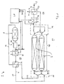
- the gas conditioning system 1 whose wiring diagram in FIG. 1 is shown, for the treatment of a gas stream G, namely a partial flow from the helium primary cooling circuit of a nuclear installation, not shown, is provided.
- the Gasuafrungssystem 1 is connected via a gas supply line 2 and a gas discharge line 4 to the helium primary cooling circuit of the nuclear installation, not shown.
- the gas treatment system 1 is provided for the targeted removal of impurities possibly carried along in the helium of the gas stream G, such as, for example, hydrogen, carbon monoxide, methane or tritium.
- impurities possibly carried along in the helium of the gas stream G, such as, for example, hydrogen, carbon monoxide, methane or tritium.
- the removal of hydrogen and carbon monoxide should be carried out via an oxidation to water or carbon dioxide, which are each deposited and retained in a switched into the gas discharge line 4, not shown molecular sieve.
- the gas purification system comprises a number of catalytic adsorber modules 6.
- Each catalytic adsorber module 6 contains a Cu-CuO mixture as the catalytic adsorber material.
- this catalytic adsorber on the one hand, its property is used as a catalyst that supports the desired implementation of hydrogen in water or carbon monoxide in carbon dioxide.
- this catalytic adsorber material also uses the ability to temporarily store oxygen, which is released as needed, ie in the desired reaction reaction, for the oxidation of hydrogen or carbon monoxide in the gas stream.
- the gas treatment system 1 also has an oxidation catalyst 8.
- the gas conditioning system is designed to avoid multiple redundancies and to minimize the number of components required for continuous operability.
- the continuous operability is provided even for the case that the CuO content in the used for the oxidation of said impurities of the gas stream G catalytic adsorber module 6 is completely or almost completely used up.
- the gas treatment system 1 comprises a plurality-in the exemplary embodiment two-identically designed catalytic adsorber modules 6.
- the catalytic adsorber modules 6 are on the gas flow side via the inflow line 10 and the outflow line 12 connected in series, wherein the oxidation catalyst 8 is connected on the gas flow side between the catalytic adsorber 6.
- the catalytic adsorber modules 6 are assigned a common switching system 14 which has a first switching unit 16 arranged at the end of the catalytic adsorber modules 6 and a second switching unit arranged at the other end of the catalytic adsorber modules 6 18 includes.
- the switching units 16, 18 are thereby, as indicated by the double arrow 20, in operative connection, so that a suitable synchronous switching of the flow path through the catalytic adsorber 6 is made possible.
- the switching system 14 is designed such that with respect to the gas flow-side position or sequence in the series connection of the first catalytic adsorber 6, the Oxidationskatalystors 8 and the second catalytic adsorber 6, the positioning of the two catalytic adsorber 6 can be exchanged.
- the catalytic adsorber module 6 shown in the figure above is connected on the input side via the outflow line 12 to the oxidation catalyst 8 and on the output side to the outflow line 4.
- FIG. 1 for a first shift position shown in FIG. 1 shown as a lower module catalytic adsorber 6 on the input side connected to the gas supply line 2 and the output side via the inflow line 10 with the oxidation catalyst 8.
- the catalytic adsorber module 6 shown in the figure above is connected on the input side via the
- FIG. 1 is represented by the dashed lines drawn switching elements in the switching units 16,18.
- the catalytic adsorber module 6 shown above is now upstream of the first catalytic adsorber module 6 via the inflow line 10
- the lower catalytic adsorber module 6 as the second catalytic adsorber module 6 passes the oxidation catalyst 8 via the outflow line 12 is downstream.
- the catalytic adsorber module 6, which is connected upstream of the oxidation catalyst 8 in the respective switching position as the first catalytic adsorber module 6, serves for the oxidation of hydrogen or carbon monoxide entrained in the gas stream G.
- the CuO content of the respective catalytic adsorber module 6 releases oxygen into the gas stream G, in order thus to allow the oxidation.
- a recuperative heat exchanger 22 is connected in the supply line 2, which is connected primary or heating side in the exhaust pipe 4.
- the recuperative heat exchanger 22 is additionally associated with an electrically operated heater 24, which together with the recuperative heat exchanger 22, a heating system 26 for the gas conditioning system 1 forms.
- the electric operable Heater 24 is controlled in terms of its heating power via a central control unit 28, which determines suitable manipulated variables for the electric heater 24 based on a variety of determined at suitable positions in the gas stream G operating parameters - as represented by the arrows 30.
- the gas stream G is passed on to the oxidation catalyst 8. There takes place in the embodiment, a degradation of entrained methane or tritium.
- a suitably selected amount of oxygen is mixed into the gas stream G via the feed unit 13.
- the feed rate for the oxygen is set via the central control unit 28 on the basis of a characteristic value determined by a sensor 32 for the fraction of impurities entrained in the gas stream G.
- an intermediate heating system 34 is connected upstream of the oxidation catalyst 8 on the gas flow side.
- the recuperative heat exchanger 36 is supplemented by an electric heater 38, which is also controlled by the central control unit 28 in terms of its heat output.
- a particularly intimate mixing of the oxygen fed in via the feed unit 13 with the gas stream G is provided before it enters the oxidation catalyst 8.
- the oxidation catalyst 8 is preceded by a suitable mixer 40, for example a static mixer.
- the gas stream G flowing out of the oxidation catalytic converter 8 still carries a residue of excess oxygen.
- the gas stream G is passed before its discharge via the second catalytic adsorber module 6, viewed on the gas flow side.
- the excess oxygen entrained in the gas stream is stored in the catalytic adsorber material held there.
- the CuO content of the catalytic adsorber material stored in the gas flow side of the second catalytic adsorber module 6 is increased by incorporation of oxygen, the Cu content of this adsorber material being reduced.
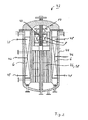
- the essential components of the gas treatment system 1 are integrated into a structural unit 42, as in longitudinal section in FIG. 2 and in cross section in FIG. 3 is shown.
- the structural unit 42 has, in particular, a pressure-resistant, essentially cylindrical outer housing 44, which is common to the said components.
- the outer housing 44 is designed for receiving the complete pressure load, so that the components arranged in it are comparatively thin-walled and without the requirement can be carried out separate mechanical load.
- the oxidation catalyst 8 is arranged above which immediately the mixer 40 is positioned.
- the feed unit 13 for the oxygen is arranged in the manner of an annular injection unit.
- recuperative heat exchanger 36 is advantageously designed as a tube bundle heat exchanger.
- the heating power of the heater 38 is adjustable. The exact arrangement of these components each associated heating elements can of course vary and be selected as needed.
- the arrangement of the recuperative heat exchanger 36 and the oxidation catalyst 8 in the central region of the structural unit 42 ensures that only comparatively small heat losses occur, so that even with only low heat output, a particularly favorable degree of conversion can be achieved.
- the two catalytic adsorber elements 6 are arranged in the embodiment rather in the outer region but within the outer housing 44. With regard to the dimensioning of the Cu / CuO reaction beds arranged therein, a ratio of reaction bed height to reaction bed length of about L / d ⁇ 4..8 is maintained. To compensate for thermal expansion compensators not shown are provided. For suitable process control, 6 temperature sensors 46 and suitably positioned sampling elements 48, which are to allow an analysis of the entrained in the gas stream G impurities arranged in the catalytic adsorber elements. The sensors provided for analysis are designed to be suitable for analyzing the contaminants. In particular, these may be gas chromatographs, mass spectrometers and / or sensors operating according to the heat dissipation or heat conduction methods.
- the gas conditioning system 1 Due to the design of the gas conditioning system 1 as an integrated unit 42, a structural decoupling of the heat-loaded components from the pressure-loaded outer housing 44 is achieved.
- the outer housing can be designed using commercially available materials with low material consumption and with the assurance of particularly high creep values, on the other hand the heat-loaded components can be made comparatively thin-walled.
- the operation of the gas treatment system 1 is in particular designed to ensure that the second catalytic adsorber element 6, as a function of the respective switching position of the switching system 14, is regenerated by appropriate admission of excess oxygen for future use. Accordingly, the supply of oxygen in the feed unit 13 is adjusted such that even after the passage of the gas stream G through the oxidation catalyst 8 still sufficient excess oxygen for storage in the respective downstream catalytic adsorber 6 is available.
- the supply of oxygen is carried out in particular such that based on the detected methane impurity in the gas stream G oxygen excess in the oxidation catalyst 8 prevails, so that even excess oxygen can be forwarded to the downstream catalytic adsorber 6.
- the feed rate for the oxygen is adjusted in such a way that, based on the total detected impurities in the gas flow G, oxygen deficiency prevails. This ensures that the amount of oxygen dissolved out of its catalytic adsorber material in the oxidation of hydrogen or carbon monoxide in the gas flow side is greater than the amount of oxygen subsequently stored in the gas catalytic side second catalytic adsorber module 6.
- the reduction reaction in the Cu-CuO mixture of the gas flow side seen first catalytic adsorber 6 runs faster than the oxidation reaction in the Cu-CuO mixture of the gas flow side seen second If, therefore, a "consumption" of oxygen in the gas flow side seen first catalytic adsorber 6 - are determined, for example, based on a hydrogen or carbon monoxide breakthrough, so is the Zuspeiserate for the oxygen in the feed unit 13 based on the total Pollution set an excess of oxygen, so that a reliable degradation of the remaining impurities in the oxidation catalyst 8 is ensured. As soon as subsequently a sufficiently high storage fraction of oxygen in the gas flow side second catalytic adsorber module 6 is detected, said switching can take place in the sequence of interconnection of the catalytic adsorber modules 6 with the oxidation catalyst 8.
Landscapes
- Engineering & Computer Science (AREA)
- Environmental & Geological Engineering (AREA)
- Chemical & Material Sciences (AREA)
- Health & Medical Sciences (AREA)
- Biomedical Technology (AREA)
- Analytical Chemistry (AREA)
- General Chemical & Material Sciences (AREA)
- Oil, Petroleum & Natural Gas (AREA)
- Chemical Kinetics & Catalysis (AREA)
- Separation Of Gases By Adsorption (AREA)
- Exhaust Gas Treatment By Means Of Catalyst (AREA)
- Catalysts (AREA)
Claims (20)
- Procédé de traitement d'un flux gazeux (G), dans lequel le flux gazeux (G) est guidé dans une première étape de purification, pour l'oxydation d'impuretés entraînées, par l'intermédiaire d'un premier module adsorbant (6) catalytique et de l'oxygène moléculaire ou atomique est ajouté et mélangé au flux gazeux (G), dans lequel le flux gazeux (G) mélangé à l'oxygène ajouté est guidé, dans une deuxième étape de purification, par l'intermédiaire d'un catalyseur d'oxydation (8) et dans lequel le flux gazeux (G) qui s'écoule du catalyseur d'oxydation (8) est guidé, dans une troisième étape de purification, pour réduire l'oxygène excédentaire, par l'intermédiaire d'un deuxième module adsorbant (6) catalytique.
- Procédé selon la revendication 1, dans lequel un mélange de Cu et de CuO est utilisé comme adsorbant catalytique dans chacun des premier et deuxième modules adsorbants (6) catalytiques.
- Procédé selon la revendication 1 ou 2, dans lequel, avant l'entrée du flux gazeux (G) dans le premier module adsorbant (6) catalytique, une valeur caractéristique est déterminée pour la part d'impuretés entraînées dans le flux gazeux (G), à la base de laquelle se règle le taux d'ajout d'oxygène au flux gazeux (G).
- Procédé selon l'une quelconque des revendications 1 à 3, dans lequel une température d'environ 400°C à 450°C est réglé pour le flux gazeux (G) lors de son entrée dans le catalyseur d'oxydation (8).
- Procédé selon l'une quelconque des revendications 1 à 4, dans lequel le flux gazeux (G) est préchauffé, avant son entrée dans le catalyseur d'oxydation (8), à l'aide d'échange de chaleur récupératif avec le flux gazeux (G) qui s'écoule du catalyseur d'oxydation (8).
- Procédé selon l'une quelconque des revendications 1 à 5, dans lequel une température d'environ 250°C est réglé pour le flux gazeux (G) lors de son entrée dans le premier module adsorbant (6) catalytique.
- Procédé selon l'une quelconque des revendications 1 à 6, dans lequel le flux gazeux (G) est préchauffé, avant son entrée dans le premier module adsorbant (6) catalytique, à l'aide d'échange de chaleur récupératif avec le flux gazeux (G) qui s'écoule du deuxième module adsorbant (6) catalytique.
- Procédé pour faire fonctionner une installation nucleaire, dans lequel un flux partiel d'un flux gazeux de refroidissement d'hélium est traité selon l'une quelconque des revendications 1 à 7.
- Procédé selon la revendication 8, dans lequel une valeur caractéristique est déterminée dans le flux gazeux (G) qui s'écoule du deuxième module adsorbant (6) catalytique, pour la part d'oxygène éventuellement entraînée, les positions du premier et deuxième modules adsorbants (6) catalytiques étant interchangées dans le chemin de flux du flux gazeux (G) après qu'une valeur limite prédéfinie de cette valeur caractéristique a été excédée.
- Système de traitement de gaz (1) ayant au moins deux modules adsorbants (6) catalytiques, qui sont montés en série en vue d'un flux gazeux (G) et entre lesquels un catalyseur d'oxydation (8) est monté du côté du flux gazeux.
- Système de traitement de gaz (1) selon la revendication 10, en amont du catalyseur d'oxydation (8) duquel est monté une unité d'alimentation (13) pour de l'oxygène moléculaire ou atomique du côté du flux gazeux.
- Système de traitement de gaz (1) selon la revendication 11, dans lequel un générateur de valeur de réglage affecté à l'unité d'alimentation (13) est relié du côté d'entrée, à un capteur (32) pour la part d'impuretés entraînées avec le flux gazeux (G), ce capteur (32) étant monté en amont du premier module adsorbant (6) catalytique vu du côté du flux gazeux.
- Système de traitement de gaz (1) selon l'une quelconque des revendications 10 à 12, dont chacun des modules adsorbants (6) catalytiques contient un mélange de Cu et de CuO comme adsorbant catalytique.
- Système de traitement de gaz (1) selon l'une quelconque des revendications 10 à 13, dans lequel un système de chauffage intermédiaire (34) est monté an amont de son catalyseur d'oxydation (8) du côté du flux gazeux.
- Système de traitement de gaz selon la revendication 14, dont le système de chauffage intermédiaire (34) comprend un échangeur de chaleur récuperatif (36), qui est monté, du côté primaire, dans une ligne d'écoulement (12), affectée au catalyseur d'oxydation (8), pour le flux gazeux (G), et qui est monté, du côté secondaire, dans une ligne d'affluence (10), affectée au catalyseur d'oxydation (8), pour le flux gazeux (G).
- Système de traitement de gaz (1) selon l'une quelconque des revendications 11 à 15, dans lequel un système de chauffage (26) est monté en amont de son premier module adsorbant (6) catalytique, vu dans la direction du flux gazeux.
- Système de traitement de gaz (1) selon la revendication 16, dont le système de chauffage (26) comprend un échangeur de chaleur récuperatif (22), qui est monté, du côté primaire, dans une ligne de décharge de gaz (4) affectée au deuxième module adsorbant (6) catalytique, et qui est monté, du côté secondaire, dans un système d'alimentation de gaz (2) affectée au premier module adsorbant (6) catalytique.
- Système de traitement de gaz (1) selon l'une quelconque des revendications 10 à 17, dans lequel un système de renversement (14) commun pour guider le flux gazeux (G) est affecté aux modules absorbants (6) catalytiques.
- Système de traitement de gaz (1) selon l'une quelconque des revendications 10 à 18, dans lequel les modules absorbants (6) catalytiques et le catalyseur d'oxydation (8) sont disposés dans un boîtier extérieur (44) commun (cuve sous pression).
- Système de traitement de gaz (1) selon l'une quelconque des revendications 10 à 19, qui est relié au flux gazeux de refroidissement d'hélium d'une installation nucléaire.
Applications Claiming Priority (3)
| Application Number | Priority Date | Filing Date | Title |
|---|---|---|---|
| DE2002146252 DE10246252B4 (de) | 2002-10-02 | 2002-10-02 | Verfahren zur Behandlung eines Gasstroms sowie Gasaufbereitungssystem |
| DE10246252 | 2002-10-02 | ||
| PCT/EP2003/010103 WO2004033076A1 (fr) | 2002-10-02 | 2003-09-11 | Procede de traitement d'un flux gazeux et systeme de traitement de gaz |
Publications (2)
| Publication Number | Publication Date |
|---|---|
| EP1549418A1 EP1549418A1 (fr) | 2005-07-06 |
| EP1549418B1 true EP1549418B1 (fr) | 2013-08-28 |
Family
ID=32010185
Family Applications (1)
| Application Number | Title | Priority Date | Filing Date |
|---|---|---|---|
| EP03750524.5A Expired - Lifetime EP1549418B1 (fr) | 2002-10-02 | 2003-09-11 | Procede de traitement d'un flux gazeux et systeme de traitement de gaz |
Country Status (9)
| Country | Link |
|---|---|
| EP (1) | EP1549418B1 (fr) |
| JP (1) | JP4328845B2 (fr) |
| CN (1) | CN100486679C (fr) |
| AU (1) | AU2003270177A1 (fr) |
| CA (1) | CA2500735C (fr) |
| DE (1) | DE10246252B4 (fr) |
| ES (1) | ES2433015T3 (fr) |
| WO (1) | WO2004033076A1 (fr) |
| ZA (1) | ZA200502441B (fr) |
Families Citing this family (5)
| Publication number | Priority date | Publication date | Assignee | Title |
|---|---|---|---|---|
| JP6191862B2 (ja) * | 2013-07-04 | 2017-09-06 | ダイハツ工業株式会社 | 水素−酸素結合装置 |
| CN107298434B (zh) * | 2017-05-24 | 2023-05-23 | 杭氧集团股份有限公司 | 一种氩气回收装置中的两级催化-吸附系统的氩气回收方法 |
| PL3689440T3 (pl) * | 2019-02-01 | 2024-05-20 | Polymetrix Ag | Sposób i urządzenie do oczyszczania krążących w obiegu gazów procesowych z termicznej obróbki materiałów sypkich |
| CN113654868B (zh) * | 2020-04-29 | 2025-03-04 | 中国科学院西北生态环境资源研究院 | 一种天然气氧化制备稀有气体样品的装置及使用方法 |
| CN112023472A (zh) * | 2020-08-24 | 2020-12-04 | 武汉第二船舶设计研究所(中国船舶重工集团公司第七一九研究所) | 一种适用于船用堆安全壳地坑的过滤系统 |
Family Cites Families (7)
| Publication number | Priority date | Publication date | Assignee | Title |
|---|---|---|---|---|
| GB1102764A (en) * | 1965-04-02 | 1968-02-07 | Atomic Energy Authority Uk | Improvements relating to nuclear reactors |
| FR2061573B1 (fr) * | 1969-07-25 | 1974-02-01 | Commissariat Energie Atomique | |
| GB1470795A (en) * | 1974-02-01 | 1977-04-21 | Atomic Energy Authority Uk | Helium cooled nuclear reactors |
| JPS5649319B2 (fr) * | 1974-11-21 | 1981-11-20 | ||
| DE2601460C2 (de) * | 1976-01-16 | 1985-05-15 | Hochtemperatur-Kernkraftwerk GmbH (HKG) Gemeinsames Europäisches Unternehmen, 4701 Uentrop | Verfahren zum Entfernen von Verunreinigungen aus dem Kühlgas von Hochtemperatur-Kernreaktoren |
| US4869883A (en) * | 1988-06-24 | 1989-09-26 | Air Products And Chemicals, Inc. | Inert gas purifier for bulk nitrogen without the use of hydrogen or other reducing gases |
| US6531105B1 (en) * | 1996-02-29 | 2003-03-11 | L'air Liquide-Societe Anonyme A'directoire Et Conseil De Surveillance Pour L'etude Et L'exploitation Des Procedes Georges Claude | Process and apparatus for removing carbon monoxide from a gas stream |
-
2002
- 2002-10-02 DE DE2002146252 patent/DE10246252B4/de not_active Expired - Fee Related
-
2003
- 2003-09-11 CA CA2500735A patent/CA2500735C/fr not_active Expired - Fee Related
- 2003-09-11 CN CNB038251132A patent/CN100486679C/zh not_active Expired - Fee Related
- 2003-09-11 EP EP03750524.5A patent/EP1549418B1/fr not_active Expired - Lifetime
- 2003-09-11 AU AU2003270177A patent/AU2003270177A1/en not_active Abandoned
- 2003-09-11 WO PCT/EP2003/010103 patent/WO2004033076A1/fr not_active Ceased
- 2003-09-11 ES ES03750524T patent/ES2433015T3/es not_active Expired - Lifetime
- 2003-09-11 JP JP2004542344A patent/JP4328845B2/ja not_active Expired - Fee Related
-
2005
- 2005-03-24 ZA ZA2005/02441A patent/ZA200502441B/en unknown
Also Published As
| Publication number | Publication date |
|---|---|
| CA2500735A1 (fr) | 2004-04-22 |
| DE10246252B4 (de) | 2008-02-07 |
| EP1549418A1 (fr) | 2005-07-06 |
| CN1694755A (zh) | 2005-11-09 |
| ZA200502441B (en) | 2005-11-30 |
| DE10246252A1 (de) | 2004-04-15 |
| CN100486679C (zh) | 2009-05-13 |
| CA2500735C (fr) | 2010-11-23 |
| ES2433015T3 (es) | 2013-12-09 |
| JP2006501989A (ja) | 2006-01-19 |
| AU2003270177A1 (en) | 2004-05-04 |
| JP4328845B2 (ja) | 2009-09-09 |
| WO2004033076A1 (fr) | 2004-04-22 |
Similar Documents
| Publication | Publication Date | Title |
|---|---|---|
| EP0504719B1 (fr) | Filtre pour gaz d'échappement et/ou convertisseur catalytique | |
| DE3121125C2 (de) | Verfahren zum Abtrennen von Wasserstoff und/oder Deuterium und Tritium aus einem Inertgasstrom sowie Vorrichtung zur Durchführung des Verfahrens im Kühlgaskreislauf eines gasgekühlten Kernreaktors | |
| EP1705739B1 (fr) | Méthode de foctionnement d'un système de pile à combustible | |
| EP1607133A1 (fr) | Installation d'épuration des gaz d'échappement dotée d'un dispositif d'alimentation en agent de réduction | |
| EP0887306B1 (fr) | Dispositif pour la production d' un gaz riche en hydrogène et pauvre en monoxyde de carbone | |
| DE69505959T2 (de) | Behandlung von abgas eines fliessbett-druckreaktionssystems | |
| EP0260530B1 (fr) | Procédé pour exécuter des réactions catalytiques | |
| EP1549418B1 (fr) | Procede de traitement d'un flux gazeux et systeme de traitement de gaz | |
| EP1118083B1 (fr) | Procede et dispositif pour recombiner de l'hydrogene et de l'oxygene dans un melange gazeux | |
| DE102019202893A1 (de) | Verfahren zur Herstellung von Ammoniak | |
| DE3412870A1 (de) | Verfahren und vorrichtung zur entfernung unerwuenschter gasfoermiger bestanteile aus rauchgasen | |
| DE3606317C2 (fr) | ||
| EP1197257B1 (fr) | Procédé et dispositif pour la production de gaz d'alimentation chaud | |
| DE3505354A1 (de) | Verfahren und vorrichtung zur entfernung unerwuenschter gasfoermiger bestandteile aus einem rauchgas | |
| DE10130776B4 (de) | Vorrichtung zum Entfernen von Schwefel aus einem Medium sowie Brennstoffzellensystem | |
| EP0161470B1 (fr) | Procédé et dispositif pour éliminer des substances gazeuses indésirables d'un gaz de fumée | |
| AT513851A4 (de) | Vorrichtung zur katalytischen Entstickung und regenerativen thermischen Nachverbrennung | |
| EP0191441B1 (fr) | Procédé pour éliminer des composants indésirables d'un gaz de fumée | |
| DE19645585C2 (de) | Verfahren und Vorrichtung zur Reinigung von Verbrennungsabgasen unterschiedlicher Strömungsrate und/oder Temperatur | |
| DE19817534A1 (de) | Verfahren und Anlage zur Erzeugung elektrischer Energie | |
| EP1106571A1 (fr) | Dispositif pour l'oxydation catalytique selective de monoxyde de carbone | |
| JP2006501989A5 (fr) | ||
| DE60309010T2 (de) | Katalytischen Zersetzung von Distickstoffmonoxid (N2O) | |
| DE10033593C1 (de) | Vorrichtung zur Erzeugung eines wasserstoffreichen Gases | |
| DE3406090C2 (fr) |
Legal Events
| Date | Code | Title | Description |
|---|---|---|---|
| PUAI | Public reference made under article 153(3) epc to a published international application that has entered the european phase |
Free format text: ORIGINAL CODE: 0009012 |
|
| AK | Designated contracting states |
Kind code of ref document: A1 Designated state(s): AT BE BG CH CY CZ DE DK EE ES FI FR GB GR HU IE IT LI LU MC NL PT RO SE SI SK TR |
|
| AX | Request for extension of the european patent |
Extension state: AL LT LV MK |
|
| 17P | Request for examination filed |
Effective date: 20050429 |
|
| DAX | Request for extension of the european patent (deleted) | ||
| RBV | Designated contracting states (corrected) |
Designated state(s): BE CH DE ES FI GB LI |
|
| RAP1 | Party data changed (applicant data changed or rights of an application transferred) |
Owner name: AREVA NP GMBH |
|
| RAP1 | Party data changed (applicant data changed or rights of an application transferred) |
Owner name: AREVA NP GMBH |
|
| REG | Reference to a national code |
Ref country code: DE Ref legal event code: R079 Ref document number: 50314877 Country of ref document: DE Free format text: PREVIOUS MAIN CLASS: B01D0053940000 Ipc: B01D0053860000 |
|
| GRAP | Despatch of communication of intention to grant a patent |
Free format text: ORIGINAL CODE: EPIDOSNIGR1 |
|
| RIC1 | Information provided on ipc code assigned before grant |
Ipc: B01D 53/86 20060101AFI20130314BHEP |
|
| INTG | Intention to grant announced |
Effective date: 20130327 |
|
| RAP1 | Party data changed (applicant data changed or rights of an application transferred) |
Owner name: AREVA GMBH |
|
| GRAS | Grant fee paid |
Free format text: ORIGINAL CODE: EPIDOSNIGR3 |
|
| GRAA | (expected) grant |
Free format text: ORIGINAL CODE: 0009210 |
|
| AK | Designated contracting states |
Kind code of ref document: B1 Designated state(s): BE CH DE ES FI GB LI |
|
| REG | Reference to a national code |
Ref country code: GB Ref legal event code: FG4D Free format text: NOT ENGLISH |
|
| REG | Reference to a national code |
Ref country code: CH Ref legal event code: EP |
|
| REG | Reference to a national code |
Ref country code: CH Ref legal event code: NV Representative=s name: E. BLUM AND CO. AG PATENT- UND MARKENANWAELTE , CH |
|
| REG | Reference to a national code |
Ref country code: DE Ref legal event code: R096 Ref document number: 50314877 Country of ref document: DE Effective date: 20131024 |
|
| PGFP | Annual fee paid to national office [announced via postgrant information from national office to epo] |
Ref country code: ES Payment date: 20130923 Year of fee payment: 11 |
|
| REG | Reference to a national code |
Ref country code: ES Ref legal event code: FG2A Ref document number: 2433015 Country of ref document: ES Kind code of ref document: T3 Effective date: 20131209 |
|
| PGFP | Annual fee paid to national office [announced via postgrant information from national office to epo] |
Ref country code: BE Payment date: 20130919 Year of fee payment: 11 |
|
| REG | Reference to a national code |
Ref country code: DE Ref legal event code: R097 Ref document number: 50314877 Country of ref document: DE |
|
| PLBE | No opposition filed within time limit |
Free format text: ORIGINAL CODE: 0009261 |
|
| STAA | Information on the status of an ep patent application or granted ep patent |
Free format text: STATUS: NO OPPOSITION FILED WITHIN TIME LIMIT |
|
| 26N | No opposition filed |
Effective date: 20140530 |
|
| REG | Reference to a national code |
Ref country code: DE Ref legal event code: R097 Ref document number: 50314877 Country of ref document: DE Effective date: 20140530 |
|
| PG25 | Lapsed in a contracting state [announced via postgrant information from national office to epo] |
Ref country code: BE Free format text: LAPSE BECAUSE OF NON-PAYMENT OF DUE FEES Effective date: 20140930 |
|
| REG | Reference to a national code |
Ref country code: ES Ref legal event code: FD2A Effective date: 20151027 |
|
| PGFP | Annual fee paid to national office [announced via postgrant information from national office to epo] |
Ref country code: FI Payment date: 20150921 Year of fee payment: 13 Ref country code: DE Payment date: 20150923 Year of fee payment: 13 |
|
| PG25 | Lapsed in a contracting state [announced via postgrant information from national office to epo] |
Ref country code: ES Free format text: LAPSE BECAUSE OF NON-PAYMENT OF DUE FEES Effective date: 20140912 |
|
| REG | Reference to a national code |
Ref country code: DE Ref legal event code: R119 Ref document number: 50314877 Country of ref document: DE |
|
| PG25 | Lapsed in a contracting state [announced via postgrant information from national office to epo] |
Ref country code: FI Free format text: LAPSE BECAUSE OF NON-PAYMENT OF DUE FEES Effective date: 20160911 |
|
| PG25 | Lapsed in a contracting state [announced via postgrant information from national office to epo] |
Ref country code: DE Free format text: LAPSE BECAUSE OF NON-PAYMENT OF DUE FEES Effective date: 20170401 |
|
| PGFP | Annual fee paid to national office [announced via postgrant information from national office to epo] |
Ref country code: CH Payment date: 20170925 Year of fee payment: 15 Ref country code: GB Payment date: 20170925 Year of fee payment: 15 |
|
| REG | Reference to a national code |
Ref country code: CH Ref legal event code: PL |
|
| GBPC | Gb: european patent ceased through non-payment of renewal fee |
Effective date: 20180911 |
|
| PG25 | Lapsed in a contracting state [announced via postgrant information from national office to epo] |
Ref country code: CH Free format text: LAPSE BECAUSE OF NON-PAYMENT OF DUE FEES Effective date: 20180930 Ref country code: LI Free format text: LAPSE BECAUSE OF NON-PAYMENT OF DUE FEES Effective date: 20180930 |
|
| PG25 | Lapsed in a contracting state [announced via postgrant information from national office to epo] |
Ref country code: GB Free format text: LAPSE BECAUSE OF NON-PAYMENT OF DUE FEES Effective date: 20180911 |