EP1548969A2 - Réglage et contrôle d'un système de télécommunication, et procédé pour l'établissement d'un type de modulation - Google Patents
Réglage et contrôle d'un système de télécommunication, et procédé pour l'établissement d'un type de modulation Download PDFInfo
- Publication number
- EP1548969A2 EP1548969A2 EP04030744A EP04030744A EP1548969A2 EP 1548969 A2 EP1548969 A2 EP 1548969A2 EP 04030744 A EP04030744 A EP 04030744A EP 04030744 A EP04030744 A EP 04030744A EP 1548969 A2 EP1548969 A2 EP 1548969A2
- Authority
- EP
- European Patent Office
- Prior art keywords
- communication
- communication means
- ratio
- control
- carrier wave
- Prior art date
- Legal status (The legal status is an assumption and is not a legal conclusion. Google has not performed a legal analysis and makes no representation as to the accuracy of the status listed.)
- Withdrawn
Links
Images



Classifications
-
- H—ELECTRICITY
- H04—ELECTRIC COMMUNICATION TECHNIQUE
- H04L—TRANSMISSION OF DIGITAL INFORMATION, e.g. TELEGRAPHIC COMMUNICATION
- H04L5/00—Arrangements affording multiple use of the transmission path
- H04L5/0091—Signalling for the administration of the divided path, e.g. signalling of configuration information
- H04L5/0094—Indication of how sub-channels of the path are allocated
-
- H—ELECTRICITY
- H04—ELECTRIC COMMUNICATION TECHNIQUE
- H04L—TRANSMISSION OF DIGITAL INFORMATION, e.g. TELEGRAPHIC COMMUNICATION
- H04L5/00—Arrangements affording multiple use of the transmission path
- H04L5/0001—Arrangements for dividing the transmission path
- H04L5/0003—Two-dimensional division
- H04L5/0005—Time-frequency
- H04L5/0007—Time-frequency the frequencies being orthogonal, e.g. OFDM(A) or DMT
-
- H—ELECTRICITY
- H04—ELECTRIC COMMUNICATION TECHNIQUE
- H04L—TRANSMISSION OF DIGITAL INFORMATION, e.g. TELEGRAPHIC COMMUNICATION
- H04L5/00—Arrangements affording multiple use of the transmission path
- H04L5/003—Arrangements for allocating sub-channels of the transmission path
- H04L5/0037—Inter-user or inter-terminal allocation
-
- H—ELECTRICITY
- H04—ELECTRIC COMMUNICATION TECHNIQUE
- H04L—TRANSMISSION OF DIGITAL INFORMATION, e.g. TELEGRAPHIC COMMUNICATION
- H04L5/00—Arrangements affording multiple use of the transmission path
- H04L5/003—Arrangements for allocating sub-channels of the transmission path
- H04L5/0044—Allocation of payload; Allocation of data channels, e.g. PDSCH or PUSCH
- H04L5/0046—Determination of the number of bits transmitted on different sub-channels
-
- H—ELECTRICITY
- H04—ELECTRIC COMMUNICATION TECHNIQUE
- H04L—TRANSMISSION OF DIGITAL INFORMATION, e.g. TELEGRAPHIC COMMUNICATION
- H04L5/00—Arrangements affording multiple use of the transmission path
- H04L5/003—Arrangements for allocating sub-channels of the transmission path
- H04L5/0058—Allocation criteria
- H04L5/006—Quality of the received signal, e.g. BER, SNR, water filling
Definitions
- the present invention relates to a control and monitoring telecommunication system for connecting and communicating between a site such as power plant and shopping mall where apparatuses to be controlled and monitored are located and a control room and monitor room where operators and observers are stationed, and also to a method of setting a modulation method for the communication.
- a need for remote monitoring or remote maintenance of existing plant has been increasing in many plants including power plant.
- a need for installing or adding monitor cameras is also increasing in view of higher security.
- Japanese Laid-open Patent Publication No. 2001-25000 paragraphs 0026-0035, Fig. 1 and Fig. 2 also discloses a telecommunication mode where multiple modems are connected with a single telecommunication line, it lists nothing else but generally known coordination methods (methods where one modem serving as master allocates the transmission right; comprising four methods: token passing, collision sensing, time division multiplex, and frequency division multiplex).
- the patent does not contain any concrete description about detailed physical layer of communication but simply refers to a reference literature on xDSL (x digital subscriber line).
- ADSL Asymmetric Digital Subscriber Line
- R American National Standards Institute, Inc. ANSI (R) Tl. 413-1998, pp. 95-135,for example.
- the document which is written on the physical layer of ADSL (asymmetric digital subscriber line), a typical xDSL, describes that, for the modems communicating with each other, training to cope with noise or attenuation and adjusting the communication setting based on the training (determining a modulation method for every carrier) are needed, explaining how to realize it.
- carrier means the frequency of carrier wave signal.
- an object of the present invention is to offer a means for performing one-to-multi telecommunication for broadcasting and coordination, guaranteeing an access right, using an existing telecommunication line, particularly a telecommunication line provided with no anti-noise measures in case the information obtained by apparatuses that have not been connected to a network or newly installed is transmitted to a monitor room or control room.
- the present invention solving the above problems is a control and monitoring telecommunication system for the communication between the apparatuses installed at a site in a specified area and a control room as well as a method of setting a modulation method.
- a modulation method by which all modems can demodulate at high probability" so that other slave stations can recognize the destination.
- a "specified area” means the premises of a plant or factory or a shopping mall.
- the "information as to the destination to/from whom the data is to be transmitted and received" is normally stored in the header.
- the master modem of this invention has a function of calculating the "modulation method by which all modems can demodulate at high probability" based on the result of the transmission path S/N ratio measured in the initialization sequence of the slave modem, and also transfers the calculation result to all slave modems after completion of the initialization sequence of all the slave modems. It is permissible to measure the data transmission error ratio instead of the S/N ratio.
- all stations can recognize the destination of the incoming communication at high probability without providing physical anti-noise measures such as shielding or physical adjustment of the transmission path characteristic such as terminal resistance. Accordingly, even if multiple stations are connected with each other on a single physical transmission path, appropriate coordination can be achieved.
- Fig. 1 shows the configuration of the control and monitoring telecommunication system according to an embodiment of the present invention applied to a plant control and monitoring system.
- the figure does not show concrete apparatuses to be controlled in a plant but only shows the control and monitoring system and its configuration.
- the plant control and monitoring system comprises a central operation room 101, control units 109, 110, 111, 112 in the operation rooms 102, 103, 104 located at the site, and telecommunication line 121 connecting all these in a serial mode.
- the control unit 109 in the central operation room 101 is connected with the telecommunication line 121 via a master station modem 105 and the control units 110, 111, 112 are connected with it via slave station modems 106, 107, 108.
- the central operation room 101 means a "control room" mentioned in the claims.
- Fig. 11 shows a basic construction of the modem 105 in Fig. 1.
- Other modems 106, 107 and 108 are constructed similarly.
- the modem 105 comprises BP filters (band pass filters) 1101, 1112, receiving amplifier 1102, transmission amplifier 1111, A/D converter (analog-to-digital converter) 1103, D/A converter (digital-to-analog converter) 1110, equalizer 1104, demodulator 1105, modulator 1109, access controller 1107, and protocol converter 1108.
- BP filters band pass filters
- A/D converter analog-to-digital converter
- D/A converter digital-to-analog converter
- the modem 105 is equipped with a protocol converter 1108 for interfacing with the control unit 109.
- the control unit 109 can be constructed as a unit, for example, based on a PC (personal computer). This construction enables to utilize various kinds of package software, thereby allowing smooth information management and data processing.
- the protocol converter 1108 is provided with external connection interface such as Ethernet (R) or USB (universal serial bus) to enable the utilization.
- the protocol converter 1108 When the protocol converter 1108 receives data to transmit to other control unit from the control unit 109, it converts the data into a communication packet in a specified format to be handled by the modem 105 and transmits the converted communication packet to the access controller 1107.
- the access controller 1107 receives the communication packet from the protocol converter 1108, it outputs the data contained in the received communication packet to the converter 1109.
- the converter 1109 allocates the data inputted from the access controller 1107 to each carrier wave signal based on the data allocation volume information 1106b, inputted separately from the access controller 1107, for the carrier wave signal of each frequency band. This is called bit allocation.
- the carrier wave signal to which the data has been allocated is then converted into an analog signal by the D/A converter 1110, amplified by the transmission amplifier 1111, outputted into the telecommunication line 121 such as a broadcasting line via the BP filter 1112, and then transmitted to other modems.
- a signal transmitted from other modem (for example, from modem 107 in the description herein) to the modem 105 is limited to a signal of a specified communication band by the BP filter 1101 and outputted to the receiving amplifier 1102.
- the receiving amplifier 1102 amplifies the signal inputted from the BP filter 1101 and outputs it to the A/D converter 1103.
- the A/D converter 1103 converts the signal inputted from the receiving amplifier 1102 into a digital signal and outputs it to the equalizer 1104.
- the equalizer 1104 which functions to correct communication path distortion (also called transmission path distortion) of the telecommunication line 121, corrects the communication path distortion for the signal inputted from the A/D converter 1103 and outputs the corrected signal to the demodulator 1105.
- the demodulator 1105 takes out the data allocated to each carrier wave signal based on the data allocation volume information 1106a, inputted separately from the access controller 1107, for the carrier wave signal of each frequency band, and outputs it to the access controller 1107.
- the access controller 1107 converts the data inputted from the demodulator 1105 into a communication packet of a specified format and outputs the converted communication packet to the protocol converter 1108.
- the protocol converter 1108 converts the protocol of the communication packet inputted from the access controller 1107 in accordance with the interface with the control unit 109 (for example, Ethernet (R) or USB), and outputs the protocol-converted information to the control unit 109.
- the access controller 1107 outputs the data allocation volume information 1106a and 1106b (carrier allocation information, which will be explained later) to the modulator 1105 and demodulator 1109, respectively.
- the data allocation volume defined by this information is not always constant. That is, training (learning) about the communication characteristic between the modem 105 and modem 107 is carried out at a specified interval so as to estimate the S/N ratio for every carrier wave signal of each frequency band or evaluate the data transmission error ratio (bit error ratio) in the communication, and the data allocation volume for every carrier wave signal of each frequency band or that for all carrier wave signals is varied. It is permissible to utilize both the estimation result of the S/N ratio and evaluation result of the data transmission error ratio to vary the data allocation volume.
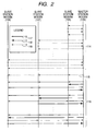
- Fig. 2 shows the communication sequence between the modems.
- Sequence 114 is called an initialization sequence.
- Broken-line arrow represents the transmission and receiving of header, training data and training result (information regarding the most suitable modulation method for each carrier obtained by a method described later, that is to say, the carrier allocation information) that has not only been modulated by a "modulation method by which all the modems connected with the telecommunication line 121 (see Fig. 1) (hereinafter, simply called all modems) can demodulate but in which no transmission path characteristic is considered" but also been coded by a coding system with high error correction capability.
- carrier means the frequency of the carrier wave signal.
- the broken-line arrow 115 is based on the same modulation method as for the other broken lines but it represents the transmission of the information on the "modulation method by which all modems can demodulate at high probability".
- Sequence 116 represents data transmission from the master station modem to slave station modems, poling to slave station modems, and data transmission from slave station modems.
- Bold-line arrow represents the transmission and receiving of header by the "modulation method by which all modems can demodulate at high probability”.
- Double-line arrow represents the transmission and receiving of user data that has been modulated by the "most suitable modulation method" in accordance with the transmission path characteristic and noise characteristic between the master station modem and slave station modems. All arrows 117, 118 and 119 means data is transmitted from their tail (small circle in Fig. 2) to their head. In the data transmission by the broken-line arrow 115, although data is transmitted to all slave station modems connected with the telecommunication line 121 (see Fig.
- all slave station modems At one time, it is permissible to transmit data individually to each slave station modem. If it applies, header is modulated by the "modulation method by which all the modems can demodulate but in which no transmission path characteristic is considered" and coded by a coding system with high error correction capability, which is different from the modulation method employed in sequence 116 for the data transmission from the master station modem to slave station modems, poling to slave station modems, and data transmission from slave station modems.
- Transferring information from a master station modem to multiple slave station modems at a time as above is called multi-destination communication or broadcasting.
- multi-destination communication is employed in order to control the network in the above case, multi-destination communication may also be needed at a higher-level application that uses a telecommunication system as above. Particularly for control application, multiple apparatuses need to be controlled simultaneously.
- the control information transmitted and received in the above application is a kind of user data for the control and monitoring telecommunication system of the present invention.
- multi-destination communication becomes necessary even for user data and therefore multi-destination communication shown by the arrow 115 may be performed even in sequence 116.
- modulating and demodulating data by the "modulation method by which all modems can demodulate at high probability", to be described later, it becomes possible to transmit the data to all slave station modems at a data transmission error ratio lower than specified.
- Ensured data transmission meaning transmission at a probability higher than specified) as above is indispensable particularly for control and monitoring application.
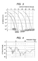
- Fig. 3 shows the relationship between the ratio of carrier power to noise (carrier power/noise, C/N ratio) and bit error ratio in each modulation method.
- Modulation method includes BPSK (binary phase shift keying), QPSK (quadrature phase shift keying), 16QAM (quadrature amplitude modulation), 64QAM and 256QAM.
- BPSK and QPSK are phase modulation method, where data volume that can be transmitted by one carrier is 1 bit and 2 bits, respectively.
- 16QAM, 64QAM and 256QAM are phase-amplitude modulation method, where data volume that can be transmitted by one carrier is 4 bits, 6 bits and 8 bits, respectively.
- Fig. 4 shows the attenuation characteristic of non-twist type paired cable with which multiple modems are connected. In the description hereinafter, this paired cable is called the telecommunication line.
- Fig. 6 shows the bit count 601 allocatable to each frequency in case the transmission power is 90 dB ⁇ V. Fig. 6 is based on such a transmission path characteristic as shown in Fig. 4 and Fig. 5. Reference value of the bit error ratio is 10 -5 .
- the bit count 601 allocatable to the carrier varies as shown in Fig. 6 depending upon the location of the modems. Accordingly, the difference between the power 602 of the received signal in Fig. 6 and noise 603 superimposing the received signal (because the "power" of the horizontal axis on the right in Fig. 6 is a logarithm of voltage, it is a "ratio" in terms of the magnitude of voltage, although a term “difference" is used) is measured in an advance training period and how many bits are allocatable to each carrier is calculated in accordance with the measured difference, and then the bit count 601 allocatable to each carrier is transmitted to the destination.
- the sender side allocates data to carriers according to this allocation, the telecommunication based on the "most suitable modulation method" can be realized.
- “most suitable” means that the bit error ratio is lower than a reference value and yet the maximum throughput (data transmission volume in a unit time) can be achieved.
- the minimum difference between the power and noise of the received signal shall be obtained and the multi-valued modulation method for each carrier shall be determined so as to be the most suitable for the minimum value. Since the bit count allocatable to each carrier can be regarded as a quantized difference between the receiving power and noise, the "modulation method by which all modems can demodulate at high probability" can be well determined provided that the carrier allocation information for the data transmission from the master station modem to the slave station modems among the data indicated in the broken-line arrow (legend 119) in Fig. 2 and training result (carrier allocation information) for the data transmission from the slave station modems to the master station modem, both collected in the master station, are utilized and the minimum allocatable bit count is employed for every combination of the above data transmission.
- FIG. 7 shows the bit count allocatable to carriers.
- Fig. 7 shows the most suitable bit allocation 701 to carriers between the modems shown in Fig. 6, and also the bit allocation 702 to carriers in the case of BPSK modulation, as an example of the "modulation method by which all the modems can demodulate but in which no transmission path characteristic is considered", where 1 bit of data can be transmitted by one carrier.
- Fig. 8 the most suitable bit allocation is obtained for the transmission between all modems and an envelope at the bottom of the chart shows the obtained bit allocation (minimum allocatable bit count).
- the bold line 801 is for a case that the transmission voltage is 90 dB ⁇ V and the broken line 802 is for a case that the transmission voltage is 120 dB ⁇ V.
- the modulation method of the carrier is 256QAM where 8 bits of data can be transmitted by one carrier.
- Fig. 7 shows the most suitable bit allocation to carriers between specific modems. Since the frequency at which the allocatable bit count becomes zero is found from place to place, it is understood that no bit allocation is preferable for the carrier that uses the frequency adjacent to them. However, when the "modulation method by which all the modems can demodulate but in which no transmission path characteristic is considered" is employed, bit allocation applies also to those carriers and therefore noise becomes greater than the received signal power. Consequently, there remains a high possibility that the signal cannot be decoded correctly. Furthermore, carriers like these are not always few.
- the modulation method like this, there is a great possibility that all modems cannot decode the header and so fair coordination cannot be accomplished unless a coding system having high error correction capability is employed at the stage of coding. Such a situation that only a specific modem has less possibility of attaining the transmission right is not allowed for the plant control and monitoring application.
- the probability for all modems to be able to decode the header can be made higher than specified, the probability to be able to attain the transmission right can be guaranteed higher than specified.
- Fig. 8 The broken line 802 in Fig. 8 is for a case that the transmission voltage is 120 dB ⁇ V and it is understand that minimum 1 bit can be allocated to every carrier under this condition. Accordingly, an applicable modulation method shall be determined beforehand, such that all carriers be modulated by the BPSK as employed in this example, and the transmission voltage enabling such allocation shall be determined, and then the information is shared commonly by all modems by means of the multi-destination communication shown by the broken-line arrow 115 in Fig. 2.
- the minimum transmission voltage that enables the predetermined modulation method (BPSK in this example) in addition to determining the most suitable bit allocation between the modems.
- the result of the calculation needs to be informed from the slave station modems to the master station modem.
- the master station modem selects the maximum out of the minimum transmission voltages informed from all slave station modems and minimum transmission voltage calculated by itself, and it is the voltage to be transmitted by the multi-destination communication shown by the broken-line arrow 115.
- the third method is described hereunder.
- the bit count that can be transmitted by this modulation method is specified in advance. Then, the minimum difference between the power and noise of the received signal is obtained for each carrier and a sum of the bit count that can be transmitted at the obtained S/N ratio is obtained. If this does not reach the specified value, the transmission power shall be increased by a specified small increment (simply adding this small increment to the difference between the power and noise of the received signal is sufficient and actual communication is not needed) and another sum of the transmittable bit count is obtained under that condition. The comparison of the sum with the specified value is repeated until the sum of the transmittable bit count exceeds the specified value.
- the result of this calculation shall be shared commonly by all modems by means of the multi-destination communication as shown by the broken-line arrow 115 in Fig. 2.
- the result of the calculation needs to be informed from the slave station modems to the master station modem.
- the master station modem selects the maximum out of the minimum transmission voltages informed from all slave station modems and minimum transmission voltage calculated by itself, and it is the voltage to be transmitted by the multi-destination communication shown by the broken-line arrow 115.
- Fairness among the modems in attaining the transmission right is not a function necessary only for a plant.
- punctuality is necessary for the motion picture data from a monitor camera in a shopping mall, and it is an application where the fairness of attaining the transmission right and its guaranteed probability are very much important.
- the camera is provided with an image processing function, including a function of calculating the differential information from a previous observation time or a function of sensing specific changes in the image, the punctuality is not always needed because the observation time of each image can be identified.
- Fig. 9 shows the operation of the master station modem and slave station modem m.
- the slave station modem m is one slave station modem out of all slave station modems and so the operation of the slave station modem m is performed by all slave station modems.
- the master station modem performs the operation for the master station modem m to all slave station modems.
- the receiver side shall recognize the modulation method of the data to be received next by referring to the content of the header already received.
- the master station modem performs the initialization process (step S901) after turning on the power and, upon its completion, performs the training process for all slave station modems.
- the slave station modem m performs the initialization process (step S902) after turning on the power and, upon its completion, repeats receiving signals from the master station modem until a training signal header addressed to itself has been received.
- steps S903 to S913 are performed between the master station modem and slave station modem m.
- the master station modem transmits a training signal header to the slave station modem m (step S903). This transmission is performed by the "modulation method by which all the modems can demodulate but in which no transmission path characteristic is considered”.
- the master station modem transmits a training signal continuously by n times to the slave station modem m (step S904).
- the number of times n of transmitting the training signal shall have been specified beforehand. The number of times of transmission will be described in detail later.
- the slave station modem m receives the training signal from the master station modem by n times. Since the training signal does not contain any data to be transmitted, no coding is performed but a signal having a specified phase pattern serves as the signal for each carrier.
- the slave station modem m Upon completion of receiving the training signal by n times, the slave station modem m calculates the S/N ratio of the received signal. Since the S/N ratio is equivalent to the difference between the power 602 of the received signal and noise 603 superimposing the received signal, both shown in Fig. 6, the bit count 601 allocatable to each carrier is determined based on this difference. In short, it performs a carrier allocation calculation for receiving data from the master station modem (step S905).
- the transmission signal is modulated by the "modulation method by which all the modems can demodulate but in which no transmission path characteristic is considered".
- the master station modem After receiving the carrier allocation information, the master station modem transmits an acknowledgment message of its receipt to the slave station modem m (step S907). Then, the master station modem transmits a training request message to the slave station modem m (step S908).
- the slave station modem m having received the receipt acknowledgment message, receives the training request message succeedingly, and transmits a training signal header to the master station modem in reply to the request (step S909). Furthermore, the slave station modem m transmits a training signal by n times continuously (step S910) and waits for carrier allocation information to be transmitted from the master station modem.
- the master station modem having transmitted a training request message to the slave station modem m (step S908), receives the training signal header and training signal from the slave station modem m and calculates the carrier allocation in the same manner as in step S905 of the slave station modem m (step S911), and then transmits the result of the calculation, i.e. carrier allocation information to the slave station modem m (step S912).
- the slave station modem m Upon receiving the carrier allocation information, the slave station modem m transmits a receipt acknowledgment message (step S913). Upon receiving the receipt acknowledgment message, the master station modem finishes the initialization sequence for the slave station modem m. After performing this initialization sequence for all slave station modems, the master station modem sets a "modulation method by which all the modems can demodulate but in which no transmission path characteristic is considered" according to the afore-mentioned method of setting the modulation method (step S914) and transmits the information on the defined modulation method to all slave station modems (step S915). In this transmission of information (step S915) and in the initialization sequence (steps S903 to S913), the "modulation method by which all the modems can demodulate but in which no transmission path characteristic is considered" shall be employed.
- the master station modem repeats the operation in steps S916 to S919 for all slave station modems.
- This can be described as follows in view of the operation between the master station modem and slave station modem m.
- the master station modem transmits a header combined with poling header to the slave station modem m (step S916). This is performed by the "modulation method by which all modems can demodulate at high probability" indicated by the information transmitted in step S915.
- the master station modem transmits data combined with poling data after modulating them by the "most suitable modulation method" in accordance with the carrier allocation information transmitted from the slave station modem m in step S906 (step S917).
- the transmission of header and data is combined with poling (acknowledgment of transmission request) in each process.
- the slave station modem m Upon completion of receiving the data combined with poling data, the slave station modem m has attained the transmission right. Consequently, the slave station modem m transmits the header (step S918) and data (step S919) to the master station modem.
- the header In transmitting the header, the "modulation method by which all modems can demodulate at high probability" indicated by the information transmitted from the master station modem in step S915 is employed.
- the "most suitable modulation method" in accordance with the carrier allocation information transmitted from the master station modem in step S912 is employed.
- a design reference shall be defined for the overhead, like less than 5% of the training interval of one second, that is, less than 50 [msec], and the training symbol number shall be defined so as to meet the design reference.
- Fig. 12 shows the relationship among the training symbol number, number of terminals and overhead in case the symbol frequency is 1/35 [msec] (symbol frequency is 35 [kHz]). If the number of terminals is increased too much or overhead allowance is decreased too much, the training symbol number decreases and consequently the measurement accuracy of the S/N ratio of each carrier degrades. To avoid this, it is recommended to set a design reference also for the minimum training symbol number.
Landscapes
- Engineering & Computer Science (AREA)
- Signal Processing (AREA)
- Computer Networks & Wireless Communication (AREA)
- Cable Transmission Systems, Equalization Of Radio And Reduction Of Echo (AREA)
- Digital Transmission Methods That Use Modulated Carrier Waves (AREA)
- Detection And Prevention Of Errors In Transmission (AREA)
- Closed-Circuit Television Systems (AREA)
- Small-Scale Networks (AREA)
Applications Claiming Priority (2)
| Application Number | Priority Date | Filing Date | Title |
|---|---|---|---|
| JP2003428871 | 2003-12-25 | ||
| JP2003428871A JP4181492B2 (ja) | 2003-12-25 | 2003-12-25 | 制御監視用通信システムおよび変調方式の設定方法 |
Publications (2)
| Publication Number | Publication Date |
|---|---|
| EP1548969A2 true EP1548969A2 (fr) | 2005-06-29 |
| EP1548969A3 EP1548969A3 (fr) | 2009-03-18 |
Family
ID=34544991
Family Applications (1)
| Application Number | Title | Priority Date | Filing Date |
|---|---|---|---|
| EP04030744A Withdrawn EP1548969A3 (fr) | 2003-12-25 | 2004-12-23 | Réglage et contrôle d'un système de télécommunication, et procédé pour l'établissement d'un type de modulation |
Country Status (3)
| Country | Link |
|---|---|
| US (1) | US7570748B2 (fr) |
| EP (1) | EP1548969A3 (fr) |
| JP (1) | JP4181492B2 (fr) |
Families Citing this family (6)
| Publication number | Priority date | Publication date | Assignee | Title |
|---|---|---|---|---|
| DE10144813A1 (de) * | 2001-09-12 | 2003-03-27 | Alstom Switzerland Ltd | Verfahren zum Optimieren einer großtechnischen Anlage, insbesondere eines Kraftwerks |
| JP2007221614A (ja) * | 2006-02-20 | 2007-08-30 | Hitachi Ltd | 自動車内通信装置 |
| US7673084B2 (en) * | 2007-02-20 | 2010-03-02 | Infineon Technologies Ag | Bus system and methods of operation using a combined data and synchronization line to communicate between bus master and slaves |
| US7796675B1 (en) * | 2008-03-12 | 2010-09-14 | Recon Dynamics, Llc | Burst spread spectrum radio system and method for site monitoring |
| CN105484604B (zh) * | 2015-12-28 | 2017-03-22 | 沈阳宝通航空机电有限公司 | 一种机库大门控制系统及方法 |
| US11314316B2 (en) * | 2018-05-21 | 2022-04-26 | Mitsubishi Electric Corporation | Modem to selectively superpose electric power |
Family Cites Families (31)
| Publication number | Priority date | Publication date | Assignee | Title |
|---|---|---|---|---|
| US4804964A (en) * | 1985-08-09 | 1989-02-14 | Nissan Motor Company, Limited | Loran-C signal receiving apparatus |
| IL82539A0 (en) * | 1987-05-15 | 1987-11-30 | Medaon Ltd | Video communication system and phase or frequency modulator included therein |
| US5357251A (en) * | 1988-03-23 | 1994-10-18 | Central Institute For The Deaf | Electronic filters, signal conversion apparatus, hearing aids and methods |
| US4947480A (en) * | 1988-10-31 | 1990-08-07 | The United States Of America As Represented By The United States Department Of Energy | Multichannel signal enhancement |
| US5371853A (en) * | 1991-10-28 | 1994-12-06 | University Of Maryland At College Park | Method and system for CELP speech coding and codebook for use therewith |
| US5675572A (en) * | 1993-07-28 | 1997-10-07 | Sony Corporation | Orthogonal frequency division multiplex modulation apparatus and orthogonal frequency division multiplex demodulation apparatus |
| JP3222001B2 (ja) * | 1993-12-14 | 2001-10-22 | ユニデン株式会社 | チャンネル切替制御方法およびそれを用いたコードレス電話機 |
| AU695092B2 (en) | 1994-06-02 | 1998-08-06 | Amati Communications Corporation | Method and apparatus for coordinating multi-point-to-point communications in a multi-tone data transmission system |
| US6181453B1 (en) * | 1995-12-28 | 2001-01-30 | Lucent Technologies, Inc. | Method and apparatus for laser performance enhancement |
| JP3449457B2 (ja) * | 1996-04-18 | 2003-09-22 | 勝元 崔 | 無線通信システムで干渉を最小化して雑音の影響を減らすための信号処理装置及び方法 |
| US6987856B1 (en) * | 1996-06-19 | 2006-01-17 | Board Of Trustees Of The University Of Illinois | Binaural signal processing techniques |
| US6141317A (en) | 1996-08-22 | 2000-10-31 | Tellabs Operations, Inc. | Apparatus and method for bandwidth management in a multi-point OFDM/DMT digital communications system |
| JP3381580B2 (ja) * | 1996-11-22 | 2003-03-04 | 株式会社豊田中央研究所 | アダプティブ通信装置 |
| FI116181B (fi) * | 1997-02-07 | 2005-09-30 | Nokia Corp | Virheenkorjausta ja virheentunnistusta hyödyntävä informaationkoodausm enetelmä ja laitteet |
| JP4143158B2 (ja) * | 1997-04-16 | 2008-09-03 | 聯華電子股▲ふん▼有限公司 | データキャリア |
| US5930312A (en) * | 1997-04-24 | 1999-07-27 | Tut Systems, Inc. | Apparatus and method for selecting different communication speeds on a data signal line |
| US6052336A (en) * | 1997-05-02 | 2000-04-18 | Lowrey, Iii; Austin | Apparatus and method of broadcasting audible sound using ultrasonic sound as a carrier |
| US6564009B2 (en) * | 1997-05-19 | 2003-05-13 | Sony Corporation | Apparatus for recording and/or reproducing data onto and/or from an optical disk and method thereof |
| CA2320892A1 (fr) | 1998-12-17 | 2000-06-22 | Wataru Matsumoto | Procede de communication et dispositif de communication |
| JP2001025000A (ja) | 1999-07-09 | 2001-01-26 | Toshiba Corp | 監視システム |
| US6584205B1 (en) * | 1999-08-26 | 2003-06-24 | American Technology Corporation | Modulator processing for a parametric speaker system |
| US6639537B1 (en) * | 2000-03-31 | 2003-10-28 | Massachusetts Institute Of Technology | Highly linear analog-to-digital conversion system and method thereof |
| DE10017600A1 (de) * | 2000-04-08 | 2001-10-11 | Bodenseewerk Geraetetech | Regler, insbesondere Lenkregler für Flugkörper |
| US6637033B1 (en) * | 2000-07-10 | 2003-10-21 | Arris International, Inc. | Signal splitter and gain adjustment system for a cable data system |
| US6556836B2 (en) * | 2001-05-02 | 2003-04-29 | Trex Enterprises Corporation | Point-to-point, millimeter wave, dual band free space gigabit per second communication link |
| US6665546B2 (en) * | 2001-05-02 | 2003-12-16 | Trex Enterprises Corporation | High speed, point-to-point, millimeter wave dated communication system |
| US6611696B2 (en) * | 2001-05-02 | 2003-08-26 | Trex Enterprises Corporation | Method and apparatus for aligning the antennas of a millimeter wave communication link using a narrow band oscillator and a power detector |
| US7158563B2 (en) | 2001-06-01 | 2007-01-02 | The Board Of Trustees Of The Leland Stanford Junior University | Dynamic digital communication system control |
| US20030193889A1 (en) | 2002-04-11 | 2003-10-16 | Intel Corporation | Wireless device and method for interference and channel adaptation in an OFDM communication system |
| US6966262B2 (en) * | 2003-07-15 | 2005-11-22 | Special Devices, Inc. | Current modulation-based communication from slave device |
| US7647063B2 (en) * | 2003-10-17 | 2010-01-12 | Telefonaktiebolaget L M Ericsson (Publ) | Method and system for outer loop power control |
-
2003
- 2003-12-25 JP JP2003428871A patent/JP4181492B2/ja not_active Expired - Fee Related
-
2004
- 2004-12-22 US US11/018,355 patent/US7570748B2/en not_active Expired - Fee Related
- 2004-12-23 EP EP04030744A patent/EP1548969A3/fr not_active Withdrawn
Also Published As
| Publication number | Publication date |
|---|---|
| JP2005191784A (ja) | 2005-07-14 |
| US7570748B2 (en) | 2009-08-04 |
| EP1548969A3 (fr) | 2009-03-18 |
| US20050141683A1 (en) | 2005-06-30 |
| JP4181492B2 (ja) | 2008-11-12 |
Similar Documents
| Publication | Publication Date | Title |
|---|---|---|
| Hayes | Modeling and analysis of computer communications networks | |
| JP4686445B2 (ja) | データ通信のための方法 | |
| McNamara | Technical aspects of data communication | |
| US8258649B2 (en) | Communicating over power distribution media | |
| AU587037B2 (en) | Ensemble modem structure for imperfect transmission media | |
| CN103297188A (zh) | 电力线通信中分段帧的传输 | |
| EP1848138B1 (fr) | Protection de systèmes de communication contre le bruit d'impulsions électrique répétitives | |
| US20030133473A1 (en) | Power line communication system | |
| US20090059782A1 (en) | Method and apparatus for extending the transmission capability of twisted pair communication systems | |
| EP1142233B1 (fr) | Appareil et procede de communications de donnees a large bande | |
| GB2332603A (en) | Multi-directional OFDM communication systems | |
| US6590893B1 (en) | Adaptive transmission system in a network | |
| US20130279552A1 (en) | Noise reduction between proximate networks | |
| EP1548969A2 (fr) | Réglage et contrôle d'un système de télécommunication, et procédé pour l'établissement d'un type de modulation | |
| EP1075103A1 (fr) | Dispositif et procede de communication | |
| WO2008147090A1 (fr) | Dispositif et procédé pour demander une bande passante et attribuer des ressources de liaison montante sur une base par groupe dans un système de communication sans fil | |
| EP2403306A1 (fr) | Intégration coordonnée de terminaux de communication sans fil secondaires dans un réseau de communication sans fil principal | |
| CN114786273B (zh) | 一种无线通信系统的数据传输方法、设备及系统 | |
| CN110166081A (zh) | 经过通信线路进行通信 | |
| US6751262B1 (en) | Data transmission method | |
| US6175316B1 (en) | Bin-to-bin differential encoding apparatus and method for a discrete multi-tone transmission system | |
| WO2001039389A1 (fr) | Procede et dispositif de communication | |
| CN107070996B (zh) | 通信系统中功率提升的方法、系统和调制解调器 | |
| WO2002011380A2 (fr) | Multiplexage a division de frequence synchrone a fenetre destine a des reseaux multipoint | |
| JP3834278B2 (ja) | Dsl接続装置及びそのマルチポイント接続方法 |
Legal Events
| Date | Code | Title | Description |
|---|---|---|---|
| PUAI | Public reference made under article 153(3) epc to a published international application that has entered the european phase |
Free format text: ORIGINAL CODE: 0009012 |
|
| AK | Designated contracting states |
Kind code of ref document: A2 Designated state(s): AT BE BG CH CY CZ DE DK EE ES FI FR GB GR HU IE IS IT LI LT LU MC NL PL PT RO SE SI SK TR |
|
| AX | Request for extension of the european patent |
Extension state: AL BA HR LV MK YU |
|
| PUAL | Search report despatched |
Free format text: ORIGINAL CODE: 0009013 |
|
| AK | Designated contracting states |
Kind code of ref document: A3 Designated state(s): AT BE BG CH CY CZ DE DK EE ES FI FR GB GR HU IE IS IT LI LT LU MC NL PL PT RO SE SI SK TR |
|
| AX | Request for extension of the european patent |
Extension state: AL BA HR LV MK YU |
|
| RIC1 | Information provided on ipc code assigned before grant |
Ipc: H04L 5/00 20060101AFI20090210BHEP |
|
| 17P | Request for examination filed |
Effective date: 20090327 |
|
| 17Q | First examination report despatched |
Effective date: 20090504 |
|
| AKX | Designation fees paid |
Designated state(s): DE FR |
|
| STAA | Information on the status of an ep patent application or granted ep patent |
Free format text: STATUS: THE APPLICATION IS DEEMED TO BE WITHDRAWN |
|
| 18D | Application deemed to be withdrawn |
Effective date: 20110701 |