EP1548902A1 - Cable processing unit - Google Patents
Cable processing unit Download PDFInfo
- Publication number
- EP1548902A1 EP1548902A1 EP04028811A EP04028811A EP1548902A1 EP 1548902 A1 EP1548902 A1 EP 1548902A1 EP 04028811 A EP04028811 A EP 04028811A EP 04028811 A EP04028811 A EP 04028811A EP 1548902 A1 EP1548902 A1 EP 1548902A1
- Authority
- EP
- European Patent Office
- Prior art keywords
- cable
- guide
- gripper
- guide tube
- feed
- Prior art date
- Legal status (The legal status is an assumption and is not a legal conclusion. Google has not performed a legal analysis and makes no representation as to the accuracy of the status listed.)
- Granted
Links
- 238000002788 crimping Methods 0.000 description 4
- 230000033001 locomotion Effects 0.000 description 4
- 230000001419 dependent effect Effects 0.000 description 2
- 238000011161 development Methods 0.000 description 1
- 230000018109 developmental process Effects 0.000 description 1
- 238000003754 machining Methods 0.000 description 1
- 230000007704 transition Effects 0.000 description 1
Images


Classifications
-
- H—ELECTRICITY
- H01—ELECTRIC ELEMENTS
- H01R—ELECTRICALLY-CONDUCTIVE CONNECTIONS; STRUCTURAL ASSOCIATIONS OF A PLURALITY OF MUTUALLY-INSULATED ELECTRICAL CONNECTING ELEMENTS; COUPLING DEVICES; CURRENT COLLECTORS
- H01R43/00—Apparatus or processes specially adapted for manufacturing, assembling, maintaining, or repairing of line connectors or current collectors or for joining electric conductors
- H01R43/28—Apparatus or processes specially adapted for manufacturing, assembling, maintaining, or repairing of line connectors or current collectors or for joining electric conductors for wire processing before connecting to contact members, not provided for in groups H01R43/02 - H01R43/26
Definitions
- the invention relates to a cable processing device with processing stations for assembling a Cable, wherein at least one feeder with Guide tube feeds the cable to the processing stations and wherein for threading the cable into the guide tube a Leadership is provided.
- the processing stations are one Cable processing device arranged in a circle, wherein a Swivel arm the cable ends the processing stations for Machining (cutting, stripping, crimping, Tüllenetzing, etc.) feeds.
- the cable ends must be the Processing stations in cable longitudinal direction as well as in Radial direction to be fed exactly.
- the gripper of the swing arm that Electric wire.
- the Zu2020genautechnik is thus only of the Travel accuracy of the swivel arm drive dependent, if the cable end in a guide tube of the gripper exactly is guided.
- the clear diameter of the guide tube must be tuned to the cable cross section that the Cable end in the guide tube only in the cable lance axis can move.
- the cross section of the processed Cable must use a corresponding guide tube so that the cable end faces the guide tube can not perform any unforeseen movements.
- a disadvantage of the known device is that the Guide aid in the swivel area or in the work area for the cable feed is arranged and also actively controlled is. In case of misbehavior of the control of the gripper and / or The guide aid are collisions between gripper and Leadership assistance inevitable.
- the invention aims to remedy this situation.
- the invention as characterized in claim 1 solves the task to avoid the disadvantages of the known device and to provide a cable processing device, the one accident-free operation guaranteed.
- the advantages achieved by the invention are in essential to see that the leadership or the cable routing outside the working area or the Swivel range of the swivel arm for the cable feed is arranged.
- the guide helps the swivel arm the pivoting movement for the cable feed or at Do not interfere with the workstations. Collisions are thus excluded. Further advantageous is that the guide is passive or without control and therefore is inexpensive to produce.
- the swivel arm moves the guide aid with the gripper open and closes at least one half of the guide, the then a positionally correct guide tube in the gripper jaw area forms. After threading the swivel arm pivots into the Zero position back, with the guide help the starting position spring load achieved.
- Fig. 1 shows a cable processing device 1 with a designed as a tape drive 2 cable feed device, wherein the tape drive 2, a cable 3 a swivel arm 4 with Gripper 5 feeds.
- the cable 3 is in a flexible Hose 6 out, with the extended cable length can be measured by means of an encoder 7 of the tape drive 2.
- the pivot arm 4 in one with a Arrow P1 symbolizes pivoting movement and / or in a with an arrow P2 symbolized linear motion offset become. Details of the drives 8 and the swing arm. 4 with gripper 5 are in the patent application EP 03405094.8 explained.
- the pivot arm 4 is in the zero position or in the Cable longitudinal axis shown in the example a Processing station is arranged with a cutter head 9, which cuts a cable end 3.1 and stripped, the Cable end 3.1 by means of gripper 5 and one on the gripper. 5 arranged guide tube 10 is held. The light Diameter of the guide tube 10 fits on the Outer diameter of the cable 3. Other guide tubes 10 with different clear diameters are in one Magazine 11 stored, the magazine 11 along the Schwenkarmweges outside the work area or the Feed area is arranged.
- the Swivel arm 4 can start and the threading of the cable 3 in the guide tube 10 of the gripper 5 is used.
- Fig. 2 shows the pivot arm 4 with gripper 5 and Guide tube 10.
- the swivel arm 4 with gripper 5 and Guide tube 10 serves as a feeder for the Supply of cable ends 3.1 to processing stations.
- L1 is the position of the pivot arm 4, in which the truncated and stripped cable end 3.1, for example a Tüllenstation is supplied, wherein the Tüllenstation a spout on the cable end 3.1 sets.
- L2 is the location denotes the swivel arm 4, in which the cable end 3.1 with the spout is supplied to a crimping station, for example, the crimping station crimping with the cable end 3.1 connects.
- the along the Schwenkarmweges outside of the work area or feed area arranged Magazine 11 with the other guide tubes 10 is shown cut. Along the Schwenkarmweges can Also several magazines 11 provided with guide tubes 10 be.
- Fig. 3 shows the pivot arm 4 with gripper 5 and opened Gripper jaws 5.1 capable of threading the cable 3 in arranged on a holder 13 of the gripper 5 Guide tube 10, which serves as a feeder for the Supply of cable ends 3.1 to processing stations serves.
- the holder 13 is for a tool-free Guide tube replacement provided.
- the swivel arm 4 with Gripper 5 is with reduced torque from the zero position from against the intended as a guide cable guide 12th been pivoted, with a pipe section 5.2 of the gripper. 5 the cable guide 12 has operated.
- the cable guide 12 bridged for threading the cable 3 in the guide tube 10 the distance between pipe section 5.2 and holder 13.
- the first processing step for example, cutting the Cable 3 performed by means of knife head 9.
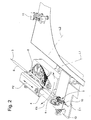
- Fig. 4 shows details of the cable guide 12 in the Rest.
- One by means of screws 15 at the table of Cable processing device 1 moored housing 16 serves as a support for an axle 17 and for a first Guide half 18.
- the housing 16 is a first Bolt 19 is arranged, which communicates with the one End of the tension spring 14.
- a second guide half 20 is rotatably mounted on the axis 17, wherein a boom 21st is provided as an actuator.
- a second pin 22 is arranged, the in communication with the other end of the tension spring 14th
- a cable guide 12 be provided, in the two guide halves 18,20 can be actuated by means of swivel arm 4.
- the inventive device can also at Cable processing equipment with several swivel arms be provided, each swivel arm at least one magazine with stock guide tubes and a cable guide is provided.
- the device according to the invention is, for example, also Applicable to cable processing equipment with linear Cable feed.
- the magazine with the guide tubes and the cable guide at one end or at the other end outside the work area of arranged the cable ends feeding device, wherein the feeder the guide tube change automatically as explained above.
Landscapes
- Engineering & Computer Science (AREA)
- Manufacturing & Machinery (AREA)
- Forwarding And Storing Of Filamentary Material (AREA)
- Manufacturing Of Electrical Connectors (AREA)
Abstract
Description
Die Erfindung betrifft eine Kabelbearbeitungseinrichtung mit Bearbeitungsstationen zur Konfektionierung eines Kabels, wobei mindestens eine Zuführeinrichtung mit Führungsrohr das Kabel den Bearbeitungsstationen zuführt und wobei zum Einfädeln des Kabels in das Führungsrohr eine Führungshilfe vorgesehen ist.The invention relates to a cable processing device with processing stations for assembling a Cable, wherein at least one feeder with Guide tube feeds the cable to the processing stations and wherein for threading the cable into the guide tube a Leadership is provided.
Üblicherweise sind die Bearbeitungsstationen einer Kabelbearbeitungseinrichtung im Kreis angeordnet, wobei ein Schwenkarm die Kabelenden den Bearbeitungsstationen zur Bearbeitung (Schneiden, Abisolieren, Crimpen, Tüllenaufsetzen, etc.) zuführt. Die Kabelenden müssen den Bearbeitungsstationen in Kabellängsrichtung wie auch in Radialrichtung genau zugeführt werden. Vor dem Schneiden und Abisolieren klemmt der Greifer des Schwenkarmes das Kabel. Die Zuführgenauigkeit ist somit nur von der Verfahrgenauigkeit des Schwenkarmantriebs abhängig, sofern das Kabelende in einem Führungsrohr des Greifers genau geführt ist. Der lichte Durchmesser des Führungsrohres muss so auf den Kabelquerschnitt abgestimmt sein, dass sich das Kabelende im Führungsrohr nur in der Kabellänasachse bewegen kann. Je nach Querschnitt des zu verarbeitenden Kabels muss ein entsprechendes Führungsrohr verwendet werden, damit das Kabelende gegenüber dem Führungsrohr keine unvorhergesehenen Bewegungen ausführen kann.Usually, the processing stations are one Cable processing device arranged in a circle, wherein a Swivel arm the cable ends the processing stations for Machining (cutting, stripping, crimping, Tüllenaufsetzen, etc.) feeds. The cable ends must be the Processing stations in cable longitudinal direction as well as in Radial direction to be fed exactly. Before cutting and stripping clamps the gripper of the swing arm that Electric wire. The Zuführgenauigkeit is thus only of the Travel accuracy of the swivel arm drive dependent, if the cable end in a guide tube of the gripper exactly is guided. The clear diameter of the guide tube must be tuned to the cable cross section that the Cable end in the guide tube only in the cable lance axis can move. Depending on the cross section of the processed Cable must use a corresponding guide tube so that the cable end faces the guide tube can not perform any unforeseen movements.
Beim Wechsel von einem Kabelquerschnitt auf einen anderen Kabelquerschnitt muss das bisher verwendete Führungsrohr des Greifers entfernt werden und ein dem neuen Querschnitt angepasstes Führungsrohr eingesetzt werden und das Kabel neu eingefädelt werden. Das voreilende Kabelende verursacht insbesondere im Greiferbereich bzw. an den Greiferbacken Probleme beim Vorschieben, wobei das Kabelende an Kanten und Übergängen ansteht. Als Abhilfe ist eine Führungshilfe vorgesehen, die bei geöffnetem Greifer den Greiferbackenbereich beim Einfädeln überbrückt. Die Führungshilfe ist vom Greifer getrennt stationär in der Kabellängsachse bzw. Nulllage angeordnet, wobei der geöffnete Greifer zum Einfädeln die Führungshilfe überfährt. Die Hälften der Führungshilfe werden mit eigenen, beispielsweise pneumatischen Aktuatoren geschlossen und das Kabel durch die trompetenförmige Führungshilfe in das Führungsrohr vorgeschoben. Danach werden die Hälften der Führungshilfe aktiv mittels der Aktuatoren geöffnet und die Greiferbacken geschlossen.When changing from one cable cross section to another Cable cross section must be the previously used guide tube the gripper will be removed and the new cross section adapted guide tube are inserted and the cable be threaded again. The leading cable end causes especially in the gripper area or on the gripper jaws Problems with advancement, whereby the cable end at edges and transitions is pending. As a remedy is a guide provided, the open gripper Gripping jaw area bridged during threading. The Guide aid is stationary in the gripper Cable longitudinal axis or zero position arranged, wherein the open gripper for threading the guide aid overruns. The halves of the guide help with own, for example, pneumatic actuators closed and the cable through the trumpet-shaped Guide aid advanced in the guide tube. After that The halves of the guide are actively using the Actuators open and the gripper jaws closed.
Nachteilig bei der bekannten Einrichtung ist, dass die Führungshilfe im Schwenkbereich bzw. im Arbeitsbereich für die Kabelzuführung angeordnet ist und zudem aktiv gesteuert ist. Bei Fehlverhalten der Steuerung des Greifers und/oder der Führungshilfe sind Kollisionen zwischen Greifer und Führungshilfen unvermeidlich.A disadvantage of the known device is that the Guide aid in the swivel area or in the work area for the cable feed is arranged and also actively controlled is. In case of misbehavior of the control of the gripper and / or The guide aid are collisions between gripper and Leadership assistance inevitable.
Hier will die Erfindung Abhilfe schaffen. Die Erfindung, wie sie in Anspruch 1 gekennzeichnet ist, löst die Aufgabe, die Nachteile der bekannten Einrichtung zu vermeiden und eine Kabelbearbeitungseinrichtung zu schaffen, die eine unfallfreie Arbeitsweise gewährleistet.The invention aims to remedy this situation. The invention, as characterized in claim 1 solves the task to avoid the disadvantages of the known device and to provide a cable processing device, the one accident-free operation guaranteed.
Vorteilhafte Weiterbildungen der Erfindung sind in den abhängigen Patentansprüchen angegeben. Advantageous developments of the invention are in the specified dependent claims.
Die durch die Erfindung erreichten Vorteile sind im wesentlichen darin zu sehen, dass die Führungshilfe bzw. die Kabelführung ausserhalb des Arbeitsbereiches bzw. des Schwenkbereiches des Schwenkarmes für die Kabelzuführung angeordnet ist. Die Führungshilfe kommt dem Schwenkarm bei der Schwenkbewegung für die Kabelzuführung bzw. beim Bedienen der Bearbeitungsstationen nicht in die Quere. Kollisionen sind somit ausgeschlossen. Weiter vorteilhaft ist, dass die Führungshilfe passiv bzw. steuerungslos ist und daher kostengünstig herstellbar ist. Der Schwenkarm fährt die Führungshilfe mit geöffnetem Greifer an und schliesst mindestens die eine Hälfte der Führungshilfe, die dann ein lagerichtiges Führungsrohr im Greiferbackenbereich bildet. Nach dem Einfädeln schwenkt der Schwenkarm in die Nulllage zurück, wobei die Führungshilfe die Ausgangslage federbeaufschlagt erreicht.The advantages achieved by the invention are in essential to see that the leadership or the cable routing outside the working area or the Swivel range of the swivel arm for the cable feed is arranged. The guide helps the swivel arm the pivoting movement for the cable feed or at Do not interfere with the workstations. Collisions are thus excluded. Further advantageous is that the guide is passive or without control and therefore is inexpensive to produce. The swivel arm moves the guide aid with the gripper open and closes at least one half of the guide, the then a positionally correct guide tube in the gripper jaw area forms. After threading the swivel arm pivots into the Zero position back, with the guide help the starting position spring load achieved.
Anhand der beiliegenden Figuren wird die vorliegende Erfindung näher erläutert.With reference to the accompanying figures, the present Invention explained in more detail.
Es zeigen:
eine Kabelbearbeitungseinrichtung,
eine Zuführeinrichtung mit Schwenkarm Greifer und Führungsrohr,
den Schwenkarm beim Einfädeln eines Kabels,
eine Kabelführung in der Ruhelage und
die Kabelführung in der Arbeitslage zum Einfädeln eines Kabels.
a cable processing device,
a feeder with swivel arm gripper and guide tube,
the swivel arm when threading a cable,
a cable guide in the rest position and
the cable guide in the working position for threading a cable.
Fig. 1 zeigt eine Kabelbearbeitungseinrichtung 1 mit einer
als Bandantrieb 2 ausgebildeten Kabelvorschubeinrichtung,
wobei der Bandantrieb 2 ein Kabel 3 einem Schwenkarm 4 mit
Greifer 5 zuführt. Das Kabel 3 ist in einem flexiblen
Schlauch 6 geführt, wobei die vorgeschobene Kabellänge
mittels eines Encoders 7 des Bandantriebes 2 messbar ist.
Mittels Antrieben 8 kann der Schwenkarm 4 in eine mit einem
Pfeil P1 symbolisierte Schwenkbewegung und/oder in eine mit
einem Pfeil P2 symbolisierte Linearbewegung versetzt
werden. Einzelheiten der Antriebe 8 und des Schwenkarmes 4
mit Greifer 5 sind in der Patentanmeldung EP 03405094.8
erläutert.Fig. 1 shows a cable processing device 1 with a
designed as a
Der Schwenkarm 4 ist in der Nulllage bzw. in der
Kabellängsachse gezeigt, in der beispielsweise eine
Bearbeitungsstation mit einem Messerkopf 9 angeordnet ist,
die ein Kabelende 3.1 anschneidet und abisoliert, wobei das
Kabelende 3.1 mittels Greifer 5 und eines am Greifer 5
angeordneten Führungsrohres 10 gehalten wird. Der lichte
Durchmesser des Führungsrohres 10 passt auf den
Aussendurchmesser des Kabels 3. Weitere Führungsrohre 10
mit unterschiedlichen lichten Durchmessern sind in einem
Magazin 11 gelagert, wobei das Magazin 11 entlang des
Schwenkarmweges ausserhalb des Arbeitsbereiches bzw. des
Zuführbereiches angeordnet ist. Im weiteren ist entlang des
Schwenkarmweges ausserhalb des Arbeitsbereiches bzw. des
Zuführbereiches eine stationäre Kabelführung 12 als
Führungshilfe im Greiferbereich vorgesehen, die der
Schwenkarm 4 anfahren kann und die dem Einfädeln des Kabels
3 in das Führungsrohr 10 des Greifers 5 dient. The
Fig. 2 zeigt den Schwenkarm 4 mit Greifer 5 und
Führungsrohr 10. Der Schwenkarm 4 mit Greifer 5 und
Führungsrohr 10 dient als Zuführeinrichtung für die
Zuführung von Kabelenden 3.1 zu Bearbeitungsstationen. Mit
L1 ist die Lage des Schwenkarmes 4 bezeichnet, in der das
angeschnittene und abisolierte Kabelende 3.1 beispielsweise
einer Tüllenstation zugeführt wird, wobei die Tüllenstation
eine Tülle auf das Kabelende 3.1 setzt. Mit L2 ist die Lage
des Schwenkarmes 4 bezeichnet, in der das Kabelende 3.1 mit
der Tülle beispielsweise einer Crimpstation zugeführt wird,
wobei die Crimpstation einen Crimpkontakt mit dem Kabelende
3.1 verbindet. Das entlang des Schwenkarmweges ausserhalb
des Arbeitsbereiches bzw. Zuführbereiches angeordnete
Magazin 11 mit den weiteren Führungsrohren 10 ist
aufgeschnitten gezeigt. Entlang des Schwenkarmweges können
auch mehrere Magazine 11 mit Führungsrohren 10 vorgesehen
sein.Fig. 2 shows the
Fig. 3 zeigt den Schwenkarm 4 mit Greifer 5 und geöffneten
Greiferbacken 5.1 in der Lage zum Einfädeln des Kabels 3 in
das an einem Halter 13 des Greifers 5 angeordnete
Führungsrohr 10, das als Zuführeinrichtung für die
Zuführung von Kabelenden 3.1 zu Bearbeitungsstationen
dient. Der Halter 13 ist für einen werkzeuglosen
Führungsrohrwechsel vorgesehen. Der Schwenkarm 4 mit
Greifer 5 ist mit reduziertem Drehmoment von der Nulllage
aus gegen die als Führungshilfe vorgesehene Kabelführung 12
geschwenkt worden, wobei ein Rohrstück 5.2 des Greifers 5
die Kabelführung 12 betätigt hat. Die Kabelführung 12
überbrückt zum Einfädeln des Kabels 3 in das Führungsrohr
10 die Distanz zwischen Rohrstück 5.2 und Halter 13. Nach
dem Einfädeln schwenkt der Schwenkarm 4 wieder in die
Nulllage zurück, wobei die Greiferbacken 5.1 geschlossen
werden und die Kabelführung 12 selbsttätig unter Einwirkung
einer Zugfeder 14 in die Ruhelage gelangt. Danach wird der
erste Bearbeitungsschritt beispielsweise Anschneiden des
Kabels 3 mittels Messerkopf 9 durchgeführt.Fig. 3 shows the
Fig. 4 zeigt Einzelheiten der Kabelführung 12 in der
Ruhelage. Ein mittels Schrauben 15 am Tisch der
Kabelbearbeitungseinrichtung 1 festgemachtes Gehäuse 16
dient als Träger für eine Achse 17 und für eine erste
Führungshälfte 18. Im weiteren ist am Gehäuse 16 ein erster
Bolzen 19 angeordnet, der in Verbindung steht mit dem einen
Ende der Zugfeder 14. Eine zweite Führungshälfte 20 ist
drehbar an der Achse 17 angeordnet, wobei ein Ausleger 21
als Betätigungsglied vorgesehen ist. An der zweiten
Führungshälfte 20 ist ein zweiter Bolzen 22 angeordnet, der
in Verbindung steht mit dem anderen Ende der Zugfeder 14.Fig. 4 shows details of the
Beim Schwenken des Schwenkarmes 4 trifft das Rohrstück 5.2
auf den Ausleger 21, und dreht den Ausleger 21 zusammen mit
der zweiten Führungshälfte 20 um die Achse 21 in die in
Fig. 5 gezeigte Lage. Dabei bilden die beiden
Führungshälften 18,20 eine trompetenförmige Öffnung 23 bzw.
ein Führungsrohr, die bzw. das das Kabel 3 wie in Fig. 3
gezeigt beim Einfädeln vom Rohrstück 5.2 zum Halter 13
führt. Beim Zurückschwenken des Schwenkarms 4 bringt die
Zugfeder 14 die zweite Führungshälfte 20 wieder in die
Ruhelage zurück.When pivoting the
Als Ausführungsvariante kann auch eine Kabelführung 12
vorgesehen sein, bei der beide Führungshälften 18,20
mittels Schwenkarm 4 betätigbar sind.As a variant, a
Die erfindungsgemässe Einrichtung kann auch bei Kabelbearbeitungseinrichtungen mit mehreren Schwenkarmen vorgesehen sein, wobei je Schwenkarm mindestens ein Magazin mit vorrätigen Führungsrohren und eine Kabelführung vorgesehen ist.The inventive device can also at Cable processing equipment with several swivel arms be provided, each swivel arm at least one magazine with stock guide tubes and a cable guide is provided.
Die erfindungsgemässe Einrichtung ist beispielsweise auch anwendbar bei Kabelbearbeitungseinrichtungen mit linearer Kabelzuführung. Bei solchen Einrichtungen ist das Magazin mit den Führungsrohren und die Kabelführung an einem Ende bzw. am anderen Ende ausserhalb des Arbeitsbereiches der die Kabelenden zuführenden Einrichtung angeordnet, wobei die Zuführeinrichtung den Führungsrohrwechsel selbsttätig wie oben erläutert ausführen kann.The device according to the invention is, for example, also Applicable to cable processing equipment with linear Cable feed. In such facilities is the magazine with the guide tubes and the cable guide at one end or at the other end outside the work area of arranged the cable ends feeding device, wherein the feeder the guide tube change automatically as explained above.
Claims (5)
dadurch gekennzeichnet, dass eine als Führungshilfe dienende Kabelführung (12) ausserhalb des Zuführbereiches der Zuführeinrichtung (4,5) für die Kabelzuführung angeordnet ist.Cable processing device (1) with processing stations for assembling a cable (3), wherein at least one feed device (4,5) with guide tube (10) feeds the cable (3) to the processing stations and wherein for threading the cable (3) into the guide tube (10 ) a guide aid (12) is provided,
characterized in that serving as a guide aid cable guide (12) outside the feed region of the feed device (4,5) is arranged for the cable feed.
dadurch gekennzeichnet, dass die Kabelführung (12) mittels der Zuführeinrichtung (4,5) betätigbar ist.Cable processing device according to claim 1,
characterized in that the cable guide (12) by means of the feed device (4,5) is actuated.
dadurch gekennzeichnet, dass die Kabelführung (12) eine erste Führungshälfte (18) und eine zweite Führungshälfte (20) aufweist, die bei Betätigung ein lagerichtiges Führungsrohr (23) im Greiferbackenbereich der Zuführeinrichtung (4,5) bilden.Cable processing device according to claim 2,
characterized in that the cable guide (12) has a first guide half (18) and a second guide half (20), which form a positionally correct guide tube (23) in the gripper jaw region of the feed device (4.5) when actuated.
dadurch gekennzeichnet, dass die zweite Führungshälfte (20) drehbar an einer Achse (17) angeordnet ist und einen Ausleger (21) aufweist, der mittels der Zuführeinrichtung (4,5) entgegen einer Federkraft betätigbar ist. Cable processing device according to claim 3,
characterized in that the second guide half (20) is rotatably arranged on an axis (17) and has a cantilever (21) which can be actuated counter to a spring force by means of the feed device (4, 5).
dadurch gekennzeichnet, dass die zweite Führungshälfte (20) mittels der Federkraft in die Ruhelage bringbar ist.Cable processing device according to claim 4,
characterized in that the second guide half (20) can be brought by means of the spring force in the rest position.
Priority Applications (1)
| Application Number | Priority Date | Filing Date | Title |
|---|---|---|---|
| EP20040028811 EP1548902B1 (en) | 2003-12-22 | 2004-12-06 | Cable processing unit |
Applications Claiming Priority (3)
| Application Number | Priority Date | Filing Date | Title |
|---|---|---|---|
| EP03405915 | 2003-12-22 | ||
| EP03405915 | 2003-12-22 | ||
| EP20040028811 EP1548902B1 (en) | 2003-12-22 | 2004-12-06 | Cable processing unit |
Publications (2)
| Publication Number | Publication Date |
|---|---|
| EP1548902A1 true EP1548902A1 (en) | 2005-06-29 |
| EP1548902B1 EP1548902B1 (en) | 2007-08-15 |
Family
ID=34553666
Family Applications (1)
| Application Number | Title | Priority Date | Filing Date |
|---|---|---|---|
| EP20040028811 Expired - Lifetime EP1548902B1 (en) | 2003-12-22 | 2004-12-06 | Cable processing unit |
Country Status (1)
| Country | Link |
|---|---|
| EP (1) | EP1548902B1 (en) |
Cited By (3)
| Publication number | Priority date | Publication date | Assignee | Title |
|---|---|---|---|---|
| US9794970B2 (en) | 2008-04-29 | 2017-10-17 | Nokia Solutions And Networks Oy | Decentralizing core network functionalities |
| US10840663B2 (en) | 2016-12-16 | 2020-11-17 | Komax Holding Ag | Cable processing device |
| EP4542793A1 (en) * | 2023-10-20 | 2025-04-23 | komax Holding AG | Cable processing machine and method for selectively picking up a cable guide unit from a magazine of a cable processing machine |
Citations (3)
| Publication number | Priority date | Publication date | Assignee | Title |
|---|---|---|---|---|
| US5210942A (en) * | 1988-06-18 | 1993-05-18 | Merz Metall-Und Kunststoffverarbeitungs Gmbh | Method for producing cable harnesses |
| US5505398A (en) * | 1990-10-10 | 1996-04-09 | Fraunhofer Gesellschaft Zur Forderung Der Angewandten Forschung E.V. | Device for supplying and exchanging a plurality of cables |
| EP0994538A2 (en) * | 1998-10-13 | 2000-04-19 | Yazaki Corporation | Automatic cutting and pressfitting apparatus for electric wire |
-
2004
- 2004-12-06 EP EP20040028811 patent/EP1548902B1/en not_active Expired - Lifetime
Patent Citations (3)
| Publication number | Priority date | Publication date | Assignee | Title |
|---|---|---|---|---|
| US5210942A (en) * | 1988-06-18 | 1993-05-18 | Merz Metall-Und Kunststoffverarbeitungs Gmbh | Method for producing cable harnesses |
| US5505398A (en) * | 1990-10-10 | 1996-04-09 | Fraunhofer Gesellschaft Zur Forderung Der Angewandten Forschung E.V. | Device for supplying and exchanging a plurality of cables |
| EP0994538A2 (en) * | 1998-10-13 | 2000-04-19 | Yazaki Corporation | Automatic cutting and pressfitting apparatus for electric wire |
Cited By (3)
| Publication number | Priority date | Publication date | Assignee | Title |
|---|---|---|---|---|
| US9794970B2 (en) | 2008-04-29 | 2017-10-17 | Nokia Solutions And Networks Oy | Decentralizing core network functionalities |
| US10840663B2 (en) | 2016-12-16 | 2020-11-17 | Komax Holding Ag | Cable processing device |
| EP4542793A1 (en) * | 2023-10-20 | 2025-04-23 | komax Holding AG | Cable processing machine and method for selectively picking up a cable guide unit from a magazine of a cable processing machine |
Also Published As
| Publication number | Publication date |
|---|---|
| EP1548902B1 (en) | 2007-08-15 |
Similar Documents
| Publication | Publication Date | Title |
|---|---|---|
| DE602005003408T2 (en) | Guiding device for a supply line in an industrial robot | |
| EP1447888B1 (en) | Gripper for a cable treating device | |
| DE602005003615T2 (en) | Arc welding robot with an applicable arrangement for the burner performance | |
| DE3041612C1 (en) | Device for the angular orientation of wire guide elements on polar or Cartesian-controlled spark erosive conical cutting systems | |
| EP1670109B1 (en) | Insulation stripping device | |
| DE602004000917T2 (en) | Arc welding robot with an applicable structure for burner performance | |
| DE69206181T2 (en) | Cable management and preparation device. | |
| DE10029749A1 (en) | Device and method for loading and / or removing workpieces on a machine tool | |
| DE602005005537T2 (en) | Arc-welding robot with an arrangement for guiding supply lines | |
| DE2615137C2 (en) | Turret lathe | |
| DE19533833A1 (en) | Bobbin winder bobbin change system | |
| EP0598276A1 (en) | Cable feeding and changing device for a cable processing machine | |
| DE68905359T2 (en) | AUTOMATIC TOOL CHANGER. | |
| EP3423243A1 (en) | Industrial robot with a protective sleeve | |
| EP2409940A1 (en) | Cable processing machine with length compensation unit | |
| EP1548903B1 (en) | Cable manufacturing assembly | |
| WO1992007399A1 (en) | Device for supplying and exchanging a plurality of cables | |
| EP3614821A1 (en) | Wiring robot and method of wiring, system and method for scheduling wiring, system and method for capturing of components | |
| DE60206212T2 (en) | Method and machine for stripping electrical cables | |
| EP0721821A2 (en) | Manipulator for machine tools | |
| DE1777294B2 (en) | TOOL CHANGING DEVICE FOR A MACHINE TOOL | |
| EP1548902A1 (en) | Cable processing unit | |
| EP4275798A1 (en) | Assembly tool and assembly system for joining components | |
| EP4275801A1 (en) | Sealant applying station and mounting system for joining components | |
| DE102020119497A1 (en) | Method and device for applying coils |
Legal Events
| Date | Code | Title | Description |
|---|---|---|---|
| PUAI | Public reference made under article 153(3) epc to a published international application that has entered the european phase |
Free format text: ORIGINAL CODE: 0009012 |
|
| AK | Designated contracting states |
Kind code of ref document: A1 Designated state(s): AT BE BG CH CY CZ DE DK EE ES FI FR GB GR HU IE IS IT LI LT LU MC NL PL PT RO SE SI SK TR |
|
| AX | Request for extension of the european patent |
Extension state: AL BA HR LV MK YU |
|
| 17P | Request for examination filed |
Effective date: 20051208 |
|
| AKX | Designation fees paid |
Designated state(s): CH DE FR GB IT LI |
|
| GRAP | Despatch of communication of intention to grant a patent |
Free format text: ORIGINAL CODE: EPIDOSNIGR1 |
|
| GRAS | Grant fee paid |
Free format text: ORIGINAL CODE: EPIDOSNIGR3 |
|
| GRAA | (expected) grant |
Free format text: ORIGINAL CODE: 0009210 |
|
| AK | Designated contracting states |
Kind code of ref document: B1 Designated state(s): CH DE FR GB IT LI |
|
| REG | Reference to a national code |
Ref country code: GB Ref legal event code: FG4D Free format text: NOT ENGLISH |
|
| RIN1 | Information on inventor provided before grant (corrected) |
Inventor name: ZURKIRCHEN, HEINZ, ING. FH |
|
| REG | Reference to a national code |
Ref country code: CH Ref legal event code: EP |
|
| REF | Corresponds to: |
Ref document number: 502004004631 Country of ref document: DE Date of ref document: 20070927 Kind code of ref document: P |
|
| GBT | Gb: translation of ep patent filed (gb section 77(6)(a)/1977) |
Effective date: 20070919 |
|
| REG | Reference to a national code |
Ref country code: CH Ref legal event code: NV Representative=s name: INVENTIO AKTIENGESELLSCHAFT |
|
| ET | Fr: translation filed | ||
| PLBE | No opposition filed within time limit |
Free format text: ORIGINAL CODE: 0009261 |
|
| STAA | Information on the status of an ep patent application or granted ep patent |
Free format text: STATUS: NO OPPOSITION FILED WITHIN TIME LIMIT |
|
| 26N | No opposition filed |
Effective date: 20080516 |
|
| PGFP | Annual fee paid to national office [announced via postgrant information from national office to epo] |
Ref country code: GB Payment date: 20081216 Year of fee payment: 5 |
|
| GBPC | Gb: european patent ceased through non-payment of renewal fee |
Effective date: 20091206 |
|
| PG25 | Lapsed in a contracting state [announced via postgrant information from national office to epo] |
Ref country code: GB Free format text: LAPSE BECAUSE OF NON-PAYMENT OF DUE FEES Effective date: 20091206 |
|
| REG | Reference to a national code |
Ref country code: FR Ref legal event code: PLFP Year of fee payment: 12 |
|
| REG | Reference to a national code |
Ref country code: FR Ref legal event code: PLFP Year of fee payment: 13 |
|
| REG | Reference to a national code |
Ref country code: FR Ref legal event code: PLFP Year of fee payment: 14 |
|
| PGFP | Annual fee paid to national office [announced via postgrant information from national office to epo] |
Ref country code: FR Payment date: 20171221 Year of fee payment: 14 |
|
| PG25 | Lapsed in a contracting state [announced via postgrant information from national office to epo] |
Ref country code: FR Free format text: LAPSE BECAUSE OF NON-PAYMENT OF DUE FEES Effective date: 20181231 |
|
| PGFP | Annual fee paid to national office [announced via postgrant information from national office to epo] |
Ref country code: IT Payment date: 20201221 Year of fee payment: 17 |
|
| PG25 | Lapsed in a contracting state [announced via postgrant information from national office to epo] |
Ref country code: IT Free format text: LAPSE BECAUSE OF NON-PAYMENT OF DUE FEES Effective date: 20211206 |
|
| PGFP | Annual fee paid to national office [announced via postgrant information from national office to epo] |
Ref country code: DE Payment date: 20231227 Year of fee payment: 20 |
|
| PGFP | Annual fee paid to national office [announced via postgrant information from national office to epo] |
Ref country code: CH Payment date: 20240102 Year of fee payment: 20 |
|
| REG | Reference to a national code |
Ref country code: DE Ref legal event code: R071 Ref document number: 502004004631 Country of ref document: DE |
|
| REG | Reference to a national code |
Ref country code: CH Ref legal event code: PL |