EP1548893A1 - Verbindung eines Elektromagnetventiles mit einem Leiterrahmen - Google Patents
Verbindung eines Elektromagnetventiles mit einem Leiterrahmen Download PDFInfo
- Publication number
- EP1548893A1 EP1548893A1 EP20040027666 EP04027666A EP1548893A1 EP 1548893 A1 EP1548893 A1 EP 1548893A1 EP 20040027666 EP20040027666 EP 20040027666 EP 04027666 A EP04027666 A EP 04027666A EP 1548893 A1 EP1548893 A1 EP 1548893A1
- Authority
- EP
- European Patent Office
- Prior art keywords
- lead frame
- terminals
- web
- projections
- solenoid
- Prior art date
- Legal status (The legal status is an assumption and is not a legal conclusion. Google has not performed a legal analysis and makes no representation as to the accuracy of the status listed.)
- Granted
Links
Images


Classifications
-
- H—ELECTRICITY
- H01—ELECTRIC ELEMENTS
- H01R—ELECTRICALLY-CONDUCTIVE CONNECTIONS; STRUCTURAL ASSOCIATIONS OF A PLURALITY OF MUTUALLY-INSULATED ELECTRICAL CONNECTING ELEMENTS; COUPLING DEVICES; CURRENT COLLECTORS
- H01R13/00—Details of coupling devices of the kinds covered by groups H01R12/70 or H01R24/00 - H01R33/00
- H01R13/46—Bases; Cases
- H01R13/533—Bases, cases made for use in extreme conditions, e.g. high temperature, radiation, vibration, corrosive environment, pressure
-
- H—ELECTRICITY
- H10—SEMICONDUCTOR DEVICES; ELECTRIC SOLID-STATE DEVICES NOT OTHERWISE PROVIDED FOR
- H10W—GENERIC PACKAGES, INTERCONNECTIONS, CONNECTORS OR OTHER CONSTRUCTIONAL DETAILS OF DEVICES COVERED BY CLASS H10
- H10W70/00—Package substrates; Interposers; Redistribution layers [RDL]
- H10W70/40—Leadframes
-
- H—ELECTRICITY
- H05—ELECTRIC TECHNIQUES NOT OTHERWISE PROVIDED FOR
- H05K—PRINTED CIRCUITS; CASINGS OR CONSTRUCTIONAL DETAILS OF ELECTRIC APPARATUS; MANUFACTURE OF ASSEMBLAGES OF ELECTRICAL COMPONENTS
- H05K7/00—Constructional details common to different types of electric apparatus
- H05K7/02—Arrangements of circuit components or wiring on supporting structure
- H05K7/12—Resilient or clamping means for holding component to structure
-
- H—ELECTRICITY
- H10—SEMICONDUCTOR DEVICES; ELECTRIC SOLID-STATE DEVICES NOT OTHERWISE PROVIDED FOR
- H10W—GENERIC PACKAGES, INTERCONNECTIONS, CONNECTORS OR OTHER CONSTRUCTIONAL DETAILS OF DEVICES COVERED BY CLASS H10
- H10W72/00—Interconnections or connectors in packages
-
- H—ELECTRICITY
- H01—ELECTRIC ELEMENTS
- H01R—ELECTRICALLY-CONDUCTIVE CONNECTIONS; STRUCTURAL ASSOCIATIONS OF A PLURALITY OF MUTUALLY-INSULATED ELECTRICAL CONNECTING ELEMENTS; COUPLING DEVICES; CURRENT COLLECTORS
- H01R13/00—Details of coupling devices of the kinds covered by groups H01R12/70 or H01R24/00 - H01R33/00
- H01R13/46—Bases; Cases
- H01R13/516—Means for holding or embracing insulating body, e.g. casing, hoods
- H01R13/518—Means for holding or embracing insulating body, e.g. casing, hoods for holding or embracing several coupling parts, e.g. frames
-
- Y—GENERAL TAGGING OF NEW TECHNOLOGICAL DEVELOPMENTS; GENERAL TAGGING OF CROSS-SECTIONAL TECHNOLOGIES SPANNING OVER SEVERAL SECTIONS OF THE IPC; TECHNICAL SUBJECTS COVERED BY FORMER USPC CROSS-REFERENCE ART COLLECTIONS [XRACs] AND DIGESTS
- Y10—TECHNICAL SUBJECTS COVERED BY FORMER USPC
- Y10T—TECHNICAL SUBJECTS COVERED BY FORMER US CLASSIFICATION
- Y10T137/00—Fluid handling
- Y10T137/598—With repair, tapping, assembly, or disassembly means
- Y10T137/5987—Solenoid or electromagnetically operated valve
-
- Y—GENERAL TAGGING OF NEW TECHNOLOGICAL DEVELOPMENTS; GENERAL TAGGING OF CROSS-SECTIONAL TECHNOLOGIES SPANNING OVER SEVERAL SECTIONS OF THE IPC; TECHNICAL SUBJECTS COVERED BY FORMER USPC CROSS-REFERENCE ART COLLECTIONS [XRACs] AND DIGESTS
- Y10—TECHNICAL SUBJECTS COVERED BY FORMER USPC
- Y10T—TECHNICAL SUBJECTS COVERED BY FORMER US CLASSIFICATION
- Y10T137/00—Fluid handling
- Y10T137/8593—Systems
- Y10T137/877—With flow control means for branched passages
- Y10T137/87885—Sectional block structure
Definitions
- the present invention relates to making an electrical connection to a solenoid and particularly a solenoid operated valve where it is desired to provide for direct plug in or bayonet-type connection.
- This technique is preferred for making electrical connection to a solenoid where a plurality of solenoid operated valves are disposed on a manifold and arranged for individually controlling an outlet pressure signal to a plurality of outlets on the manifold for control purposes.
- Such an arrangement of plural valves on a manifold is found in control modules for automatic speed change power transmissions as, for example, automatic transmissions employed in motor vehicles and particularly passenger cars and light trucks.
- the present invention provides the electrical terminals on a solenoid operated valve with support stanchions molded therearound and a web is disposed therebetween, which web is engaged on opposite sides thereof by a pair of stanchions provided on an electrical lead frame which is engaged by bayonet connection with the terminals.
- the stanchions are integrally formed with the lead frame; and, the terminal stanchions and web are integrally molded with the solenoid component structure.
- a plurality of valves on a manifold each have their terminals bayonet connected to a common lead frame.
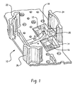
- FIG. 1 is a perspective view of a portion of the electrical lead frame of the present invention
- FIG. 2 is a perspective view of the solenoid valve on the present invention illustrating the electrical terminals, stanchions and web;
- FIG. 3 is an exploded view of the assembly of the valve onto the lead frame
- FIG. 4 is another exploded view of the assembly taken from the end of the lead frame.
- an electrical lead frame indicated generally at 10 has a first and second cutout 12, 14 formed therein in spaced relationship, each having a slot such as slot 16 formed in the access 14, which slot is formed in an electrically conductive member and adapted for making electrical connection to circuitry (not shown) within the lead frame.
- a similar slot is formed in the recess or opening 12.
- Lead frame 10 Disposed between the openings 12, 14 are a pair of upstanding lugs or projections 18, 20 which are spaced a predetermined distance apart for facilitating assembly as will hereinafter be described.
- Lead frame 10 also includes guide lugs 22, 24, 26 disposed in spaced arrangement as shown in FIG. 1 and which may be formed integrally with the lead frame for guiding assembly of the valve as will hereinafter be described.
- guide lugs 22, 24, 26 disposed in spaced arrangement as shown in FIG. 1 and which may be formed integrally with the lead frame for guiding assembly of the valve as will hereinafter be described.
- a solenoid operated valve indicated generally at 30 includes a solenoid 32 attached to a valve body 34 for, upon electrical energization, effecting operation of the valve.
- the solenoid 32 has a pair of upstanding spaced connector terminal 36, 38 which extend upwardly from the solenoid in generally spaced parallel arrangement as is well known in the art.
- the terminals 36, 38 are preferably supported by stanchions respectively 40, 42 which may be integrally molded with the solenoid coil bobbin flange or other component of the solenoid.
- the stanchions 40, 42 have disposed therebetween a web 44 which in the presently preferred practice is integrally molded with the stanchions 40, 42.
- the web is sized and configured to closely interfit in the space between the projections 18, 20 on the lead frame; and, thus provides additional support upon bayonet assembly of the terminals 36, 38 into the slots, such as slot 16, upon assembly of the solenoid 30 to the lead frame 10.
- the stanchions 36, 38 and web 44 are formed of molded plastic material of suitable strength as, for example, glass filled polyamide material, to provide resistance against vibration and inertial loads encountered in automotive power transmission applications.
- guide lugs 22, 24, 26 are disposed and arranged to slidably engage the exterior of the solenoid 32 upon assembly of the solenoid to the lead frame for more accurately locating the lead frame over the solenoid.
- lead frame 10 may have a plurality of lug sets such as 22, 24, 26, with each set for locating one of a group of solenoids so as to position and locate the lead frame on the solenoids.
- FIGS. 3 and 4 the arrangement of the lead frame with respect to the solenoid prior to assembly is shown in exploded view.
- the present invention provides a simple and cost effective technique for providing additional support and robustness to the connection of an electrical lead frame to a solenoid or group of solenoids which is suitable for severe environment applications, as for example, automotive power transmission applications.
Landscapes
- Engineering & Computer Science (AREA)
- Microelectronics & Electronic Packaging (AREA)
- Magnetically Actuated Valves (AREA)
- Control Of Transmission Device (AREA)
- Electromagnets (AREA)
- Fluid-Damping Devices (AREA)
Applications Claiming Priority (2)
| Application Number | Priority Date | Filing Date | Title |
|---|---|---|---|
| US10/722,316 US7214103B2 (en) | 2003-11-25 | 2003-11-25 | Connecting a solenoid to a lead frame |
| US722316 | 2003-11-25 |
Publications (2)
| Publication Number | Publication Date |
|---|---|
| EP1548893A1 true EP1548893A1 (de) | 2005-06-29 |
| EP1548893B1 EP1548893B1 (de) | 2007-02-14 |
Family
ID=34552744
Family Applications (1)
| Application Number | Title | Priority Date | Filing Date |
|---|---|---|---|
| EP20040027666 Expired - Lifetime EP1548893B1 (de) | 2003-11-25 | 2004-11-22 | Verbindung eines Elektromagnetventiles mit einem Leiterrahmen |
Country Status (9)
| Country | Link |
|---|---|
| US (1) | US7214103B2 (de) |
| EP (1) | EP1548893B1 (de) |
| JP (1) | JP4626846B2 (de) |
| KR (1) | KR101087841B1 (de) |
| AT (1) | ATE354189T1 (de) |
| AU (1) | AU2004231251B2 (de) |
| CA (1) | CA2488257C (de) |
| DE (1) | DE602004004743T2 (de) |
| MX (1) | MXPA04011700A (de) |
Families Citing this family (11)
| Publication number | Priority date | Publication date | Assignee | Title |
|---|---|---|---|---|
| DE102006042924A1 (de) * | 2006-09-13 | 2008-03-27 | Wabco Gmbh | Elektrische Steckverbindung mit Führung |
| US7740507B2 (en) * | 2008-02-22 | 2010-06-22 | Acutex, Inc. | Coupling for solenoid and lead frame |
| US8616351B2 (en) | 2009-10-06 | 2013-12-31 | Tenneco Automotive Operating Company Inc. | Damper with digital valve |
| US9884533B2 (en) | 2013-02-28 | 2018-02-06 | Tenneco Automotive Operating Company Inc. | Autonomous control damper |
| JP6346908B2 (ja) | 2013-02-28 | 2018-06-20 | テネコ オートモティブ オペレーティング カンパニー インコーポレイテッドTenneco Automotive Operating Company Inc. | 統合された電子回路を有するダンパ |
| US9217483B2 (en) | 2013-02-28 | 2015-12-22 | Tenneco Automotive Operating Company Inc. | Valve switching controls for adjustable damper |
| US9879748B2 (en) | 2013-03-15 | 2018-01-30 | Tenneco Automotive Operating Company Inc. | Two position valve with face seal and pressure relief port |
| US9879746B2 (en) | 2013-03-15 | 2018-01-30 | Tenneco Automotive Operating Company Inc. | Rod guide system and method with multiple solenoid valve cartridges and multiple pressure regulated valve assemblies |
| US10479160B2 (en) | 2017-06-06 | 2019-11-19 | Tenneco Automotive Operating Company Inc. | Damper with printed circuit board carrier |
| US10588233B2 (en) | 2017-06-06 | 2020-03-10 | Tenneco Automotive Operating Company Inc. | Damper with printed circuit board carrier |
| JP2023006183A (ja) * | 2021-06-30 | 2023-01-18 | 日本電産トーソク株式会社 | 電磁弁モジュール |
Citations (3)
| Publication number | Priority date | Publication date | Assignee | Title |
|---|---|---|---|---|
| EP0519202A1 (de) * | 1991-06-08 | 1992-12-23 | Robert Bosch Gmbh | Elektrisches Gerät mit wenigstens einem Kontaktstift und einer Leiterbahnfolie |
| US5892659A (en) * | 1995-12-12 | 1999-04-06 | The Whitaker Corporation | Retention system for solenoid coils |
| US6503095B1 (en) * | 1999-09-17 | 2003-01-07 | Yazaki Corporation | Terminal lug and wiring board provided with the same |
Family Cites Families (14)
| Publication number | Priority date | Publication date | Assignee | Title |
|---|---|---|---|---|
| US1157026A (en) * | 1911-10-20 | 1915-10-19 | William F Meschenmoser | Plug-switch. |
| US4186363A (en) * | 1977-08-18 | 1980-01-29 | Eaton Corporation | Solenoid assembly for elevated temperature service |
| JPS5977677U (ja) * | 1982-11-16 | 1984-05-25 | 古河機械金属株式会社 | 電磁弁の配線装置 |
| US4759730A (en) * | 1983-02-18 | 1988-07-26 | Cooper Industries, Inc. | Polarized fuseholder assembly |
| DE3634349C1 (de) * | 1986-10-09 | 1987-05-21 | Daimler Benz Ag | Baugruppe aus mehreren unabhaengig voneinander elektromagnetisch schaltbaren Wegeventilen |
| JPH01128076U (de) * | 1988-02-26 | 1989-08-31 | ||
| JPH0647187Y2 (ja) * | 1990-06-13 | 1994-11-30 | 鐘淵化学工業株式会社 | ピンチ弁密集配置構造 |
| JPH03181686A (ja) * | 1990-10-20 | 1991-08-07 | Smc Corp | 電磁弁マニホールド |
| JPH04237978A (ja) * | 1991-01-18 | 1992-08-26 | Amp Japan Ltd | タップコネクタ |
| US5677515A (en) * | 1991-10-18 | 1997-10-14 | Trw Inc. | Shielded multilayer printed wiring board, high frequency, high isolation |
| JPH06241342A (ja) * | 1993-02-19 | 1994-08-30 | Aisin Seiki Co Ltd | 電磁弁装置 |
| US5845672A (en) * | 1996-12-10 | 1998-12-08 | General Motors Corporation | Solenoid coil positioning assembly |
| US20040118466A1 (en) * | 2002-12-19 | 2004-06-24 | Eaton Corporation | Electro-hydraulic manifold assembly and pressure sensor therefor |
| US6929031B2 (en) * | 2003-03-28 | 2005-08-16 | Eaton Corporation | Electro-hydraulic manifold assembly with lead frame mounted pressure sensors |
-
2003
- 2003-11-25 US US10/722,316 patent/US7214103B2/en not_active Expired - Fee Related
-
2004
- 2004-11-22 EP EP20040027666 patent/EP1548893B1/de not_active Expired - Lifetime
- 2004-11-22 AT AT04027666T patent/ATE354189T1/de not_active IP Right Cessation
- 2004-11-22 DE DE200460004743 patent/DE602004004743T2/de not_active Expired - Lifetime
- 2004-11-23 AU AU2004231251A patent/AU2004231251B2/en not_active Ceased
- 2004-11-24 CA CA 2488257 patent/CA2488257C/en not_active Expired - Fee Related
- 2004-11-24 KR KR1020040096989A patent/KR101087841B1/ko not_active Expired - Fee Related
- 2004-11-25 MX MXPA04011700A patent/MXPA04011700A/es active IP Right Grant
- 2004-11-25 JP JP2004340458A patent/JP4626846B2/ja not_active Expired - Fee Related
Patent Citations (3)
| Publication number | Priority date | Publication date | Assignee | Title |
|---|---|---|---|---|
| EP0519202A1 (de) * | 1991-06-08 | 1992-12-23 | Robert Bosch Gmbh | Elektrisches Gerät mit wenigstens einem Kontaktstift und einer Leiterbahnfolie |
| US5892659A (en) * | 1995-12-12 | 1999-04-06 | The Whitaker Corporation | Retention system for solenoid coils |
| US6503095B1 (en) * | 1999-09-17 | 2003-01-07 | Yazaki Corporation | Terminal lug and wiring board provided with the same |
Also Published As
| Publication number | Publication date |
|---|---|
| EP1548893B1 (de) | 2007-02-14 |
| JP4626846B2 (ja) | 2011-02-09 |
| KR20050050575A (ko) | 2005-05-31 |
| US20050109536A1 (en) | 2005-05-26 |
| MXPA04011700A (es) | 2005-10-26 |
| DE602004004743T2 (de) | 2007-11-22 |
| AU2004231251B2 (en) | 2009-11-26 |
| DE602004004743D1 (de) | 2007-03-29 |
| CA2488257C (en) | 2008-10-28 |
| AU2004231251A1 (en) | 2005-06-09 |
| KR101087841B1 (ko) | 2011-11-30 |
| US7214103B2 (en) | 2007-05-08 |
| ATE354189T1 (de) | 2007-03-15 |
| CA2488257A1 (en) | 2005-05-25 |
| JP2005155918A (ja) | 2005-06-16 |
Similar Documents
| Publication | Publication Date | Title |
|---|---|---|
| CA2488257C (en) | Connecting a solenoid to a lead frame | |
| US5449227A (en) | Solenoid attachment for antilock brake system | |
| US4728916A (en) | Solenoid operated fluid control valve | |
| US5611372A (en) | Arrangement of solenoid valves, a central plug and a printed circuit board on a control housing of an automatic shift device of a toothed-wheel variable-speed gearbox | |
| EP0334343B1 (de) | Kabelbaumkupplungselement an einem Instrumentenbrett | |
| US6164732A (en) | Pressure controlling device for vehicle | |
| US5853231A (en) | Pressure control device | |
| US5941282A (en) | Electromagnetic valve unit | |
| US6745634B2 (en) | Pressure control device | |
| US5474108A (en) | Electromagnetic valve unit | |
| US6368119B2 (en) | Electrical connection box | |
| US6000679A (en) | Solenoid coil attachment mechanism | |
| US6388885B1 (en) | Controller with helical spring contacts | |
| JP2009545294A (ja) | 統合された駆動エレメント | |
| US20030042789A1 (en) | Device for mounting coil assemblies of solenoid valves in electronically controlled brake systems | |
| US5662392A (en) | Electrohydraulic pressure control device | |
| CN111630303B (zh) | 阀组件和包括该阀组件的致动组件 | |
| US6220300B1 (en) | Module, especially a module for an electrohydraulic transmission controlling device | |
| WO2005030528A2 (en) | Solenoid coil having interior terminals and method for fixing | |
| GB2313484A (en) | Solenoid assembly for anti-lock braking system | |
| EP3913776B1 (de) | Antriebsanordnung | |
| EP4502439A1 (de) | Elektrische komponentenanordnung, herstellungsverfahren für elektrische komponentenanordnung und hydraulische drucksteuerungsvorrichtung für fahrzeugbremsen | |
| CN111756228B (zh) | 驱动电路及制作方法、致动器装置以及机动车辆部件 | |
| KR100847479B1 (ko) | 차량용 안티록 브레이크 시스템 전자제어유닛 하우징어셈블리 | |
| JP7596046B2 (ja) | 充電インレット |
Legal Events
| Date | Code | Title | Description |
|---|---|---|---|
| PUAI | Public reference made under article 153(3) epc to a published international application that has entered the european phase |
Free format text: ORIGINAL CODE: 0009012 |
|
| AK | Designated contracting states |
Kind code of ref document: A1 Designated state(s): AT BE BG CH CY CZ DE DK EE ES FI FR GB GR HU IE IS IT LI LU MC NL PL PT RO SE SI SK TR |
|
| AX | Request for extension of the european patent |
Extension state: AL HR LT LV MK YU |
|
| 17P | Request for examination filed |
Effective date: 20051013 |
|
| AKX | Designation fees paid |
Designated state(s): AT BE BG CH CY CZ DE DK EE ES FI FR GB GR HU IE IS IT LI LU MC NL PL PT RO SE SI SK TR |
|
| GRAP | Despatch of communication of intention to grant a patent |
Free format text: ORIGINAL CODE: EPIDOSNIGR1 |
|
| GRAS | Grant fee paid |
Free format text: ORIGINAL CODE: EPIDOSNIGR3 |
|
| GRAA | (expected) grant |
Free format text: ORIGINAL CODE: 0009210 |
|
| AK | Designated contracting states |
Kind code of ref document: B1 Designated state(s): AT BE BG CH CY CZ DE DK EE ES FI FR GB GR HU IE IS IT LI LU MC NL PL PT RO SE SI SK TR |
|
| PG25 | Lapsed in a contracting state [announced via postgrant information from national office to epo] |
Ref country code: PL Free format text: LAPSE BECAUSE OF FAILURE TO SUBMIT A TRANSLATION OF THE DESCRIPTION OR TO PAY THE FEE WITHIN THE PRESCRIBED TIME-LIMIT Effective date: 20070214 Ref country code: AT Free format text: LAPSE BECAUSE OF FAILURE TO SUBMIT A TRANSLATION OF THE DESCRIPTION OR TO PAY THE FEE WITHIN THE PRESCRIBED TIME-LIMIT Effective date: 20070214 Ref country code: DK Free format text: LAPSE BECAUSE OF FAILURE TO SUBMIT A TRANSLATION OF THE DESCRIPTION OR TO PAY THE FEE WITHIN THE PRESCRIBED TIME-LIMIT Effective date: 20070214 Ref country code: FI Free format text: LAPSE BECAUSE OF FAILURE TO SUBMIT A TRANSLATION OF THE DESCRIPTION OR TO PAY THE FEE WITHIN THE PRESCRIBED TIME-LIMIT Effective date: 20070214 Ref country code: BE Free format text: LAPSE BECAUSE OF FAILURE TO SUBMIT A TRANSLATION OF THE DESCRIPTION OR TO PAY THE FEE WITHIN THE PRESCRIBED TIME-LIMIT Effective date: 20070214 Ref country code: LI Free format text: LAPSE BECAUSE OF FAILURE TO SUBMIT A TRANSLATION OF THE DESCRIPTION OR TO PAY THE FEE WITHIN THE PRESCRIBED TIME-LIMIT Effective date: 20070214 Ref country code: CH Free format text: LAPSE BECAUSE OF FAILURE TO SUBMIT A TRANSLATION OF THE DESCRIPTION OR TO PAY THE FEE WITHIN THE PRESCRIBED TIME-LIMIT Effective date: 20070214 Ref country code: SI Free format text: LAPSE BECAUSE OF FAILURE TO SUBMIT A TRANSLATION OF THE DESCRIPTION OR TO PAY THE FEE WITHIN THE PRESCRIBED TIME-LIMIT Effective date: 20070214 Ref country code: NL Free format text: LAPSE BECAUSE OF FAILURE TO SUBMIT A TRANSLATION OF THE DESCRIPTION OR TO PAY THE FEE WITHIN THE PRESCRIBED TIME-LIMIT Effective date: 20070214 |
|
| REG | Reference to a national code |
Ref country code: GB Ref legal event code: FG4D |
|
| REG | Reference to a national code |
Ref country code: CH Ref legal event code: EP |
|
| REF | Corresponds to: |
Ref document number: 602004004743 Country of ref document: DE Date of ref document: 20070329 Kind code of ref document: P |
|
| REG | Reference to a national code |
Ref country code: IE Ref legal event code: FG4D |
|
| PG25 | Lapsed in a contracting state [announced via postgrant information from national office to epo] |
Ref country code: BG Free format text: LAPSE BECAUSE OF FAILURE TO SUBMIT A TRANSLATION OF THE DESCRIPTION OR TO PAY THE FEE WITHIN THE PRESCRIBED TIME-LIMIT Effective date: 20070515 |
|
| PG25 | Lapsed in a contracting state [announced via postgrant information from national office to epo] |
Ref country code: ES Free format text: LAPSE BECAUSE OF FAILURE TO SUBMIT A TRANSLATION OF THE DESCRIPTION OR TO PAY THE FEE WITHIN THE PRESCRIBED TIME-LIMIT Effective date: 20070525 |
|
| REG | Reference to a national code |
Ref country code: SE Ref legal event code: TRGR |
|
| PG25 | Lapsed in a contracting state [announced via postgrant information from national office to epo] |
Ref country code: IS Free format text: LAPSE BECAUSE OF FAILURE TO SUBMIT A TRANSLATION OF THE DESCRIPTION OR TO PAY THE FEE WITHIN THE PRESCRIBED TIME-LIMIT Effective date: 20070614 |
|
| PG25 | Lapsed in a contracting state [announced via postgrant information from national office to epo] |
Ref country code: PT Free format text: LAPSE BECAUSE OF FAILURE TO SUBMIT A TRANSLATION OF THE DESCRIPTION OR TO PAY THE FEE WITHIN THE PRESCRIBED TIME-LIMIT Effective date: 20070716 |
|
| ET | Fr: translation filed | ||
| NLV1 | Nl: lapsed or annulled due to failure to fulfill the requirements of art. 29p and 29m of the patents act | ||
| REG | Reference to a national code |
Ref country code: CH Ref legal event code: PL |
|
| PG25 | Lapsed in a contracting state [announced via postgrant information from national office to epo] |
Ref country code: SK Free format text: LAPSE BECAUSE OF FAILURE TO SUBMIT A TRANSLATION OF THE DESCRIPTION OR TO PAY THE FEE WITHIN THE PRESCRIBED TIME-LIMIT Effective date: 20070214 |
|
| PLBE | No opposition filed within time limit |
Free format text: ORIGINAL CODE: 0009261 |
|
| STAA | Information on the status of an ep patent application or granted ep patent |
Free format text: STATUS: NO OPPOSITION FILED WITHIN TIME LIMIT |
|
| PG25 | Lapsed in a contracting state [announced via postgrant information from national office to epo] |
Ref country code: CZ Free format text: LAPSE BECAUSE OF FAILURE TO SUBMIT A TRANSLATION OF THE DESCRIPTION OR TO PAY THE FEE WITHIN THE PRESCRIBED TIME-LIMIT Effective date: 20070214 Ref country code: RO Free format text: LAPSE BECAUSE OF FAILURE TO SUBMIT A TRANSLATION OF THE DESCRIPTION OR TO PAY THE FEE WITHIN THE PRESCRIBED TIME-LIMIT Effective date: 20070214 |
|
| 26N | No opposition filed |
Effective date: 20071115 |
|
| PG25 | Lapsed in a contracting state [announced via postgrant information from national office to epo] |
Ref country code: GR Free format text: LAPSE BECAUSE OF FAILURE TO SUBMIT A TRANSLATION OF THE DESCRIPTION OR TO PAY THE FEE WITHIN THE PRESCRIBED TIME-LIMIT Effective date: 20070515 |
|
| PG25 | Lapsed in a contracting state [announced via postgrant information from national office to epo] |
Ref country code: MC Free format text: LAPSE BECAUSE OF NON-PAYMENT OF DUE FEES Effective date: 20071130 |
|
| PG25 | Lapsed in a contracting state [announced via postgrant information from national office to epo] |
Ref country code: IE Free format text: LAPSE BECAUSE OF NON-PAYMENT OF DUE FEES Effective date: 20071122 |
|
| PG25 | Lapsed in a contracting state [announced via postgrant information from national office to epo] |
Ref country code: EE Free format text: LAPSE BECAUSE OF FAILURE TO SUBMIT A TRANSLATION OF THE DESCRIPTION OR TO PAY THE FEE WITHIN THE PRESCRIBED TIME-LIMIT Effective date: 20070214 |
|
| PG25 | Lapsed in a contracting state [announced via postgrant information from national office to epo] |
Ref country code: CY Free format text: LAPSE BECAUSE OF FAILURE TO SUBMIT A TRANSLATION OF THE DESCRIPTION OR TO PAY THE FEE WITHIN THE PRESCRIBED TIME-LIMIT Effective date: 20070214 |
|
| PG25 | Lapsed in a contracting state [announced via postgrant information from national office to epo] |
Ref country code: LU Free format text: LAPSE BECAUSE OF NON-PAYMENT OF DUE FEES Effective date: 20071122 |
|
| PG25 | Lapsed in a contracting state [announced via postgrant information from national office to epo] |
Ref country code: TR Free format text: LAPSE BECAUSE OF FAILURE TO SUBMIT A TRANSLATION OF THE DESCRIPTION OR TO PAY THE FEE WITHIN THE PRESCRIBED TIME-LIMIT Effective date: 20070214 Ref country code: HU Free format text: LAPSE BECAUSE OF FAILURE TO SUBMIT A TRANSLATION OF THE DESCRIPTION OR TO PAY THE FEE WITHIN THE PRESCRIBED TIME-LIMIT Effective date: 20070815 |
|
| PGFP | Annual fee paid to national office [announced via postgrant information from national office to epo] |
Ref country code: FR Payment date: 20131025 Year of fee payment: 10 Ref country code: SE Payment date: 20131107 Year of fee payment: 10 Ref country code: GB Payment date: 20131028 Year of fee payment: 10 Ref country code: DE Payment date: 20131129 Year of fee payment: 10 |
|
| PGFP | Annual fee paid to national office [announced via postgrant information from national office to epo] |
Ref country code: IT Payment date: 20131122 Year of fee payment: 10 |
|
| REG | Reference to a national code |
Ref country code: DE Ref legal event code: R119 Ref document number: 602004004743 Country of ref document: DE |
|
| REG | Reference to a national code |
Ref country code: SE Ref legal event code: EUG |
|
| GBPC | Gb: european patent ceased through non-payment of renewal fee |
Effective date: 20141122 |
|
| PG25 | Lapsed in a contracting state [announced via postgrant information from national office to epo] |
Ref country code: SE Free format text: LAPSE BECAUSE OF NON-PAYMENT OF DUE FEES Effective date: 20141123 |
|
| REG | Reference to a national code |
Ref country code: FR Ref legal event code: ST Effective date: 20150731 |
|
| PG25 | Lapsed in a contracting state [announced via postgrant information from national office to epo] |
Ref country code: GB Free format text: LAPSE BECAUSE OF NON-PAYMENT OF DUE FEES Effective date: 20141122 Ref country code: DE Free format text: LAPSE BECAUSE OF NON-PAYMENT OF DUE FEES Effective date: 20150602 |
|
| PG25 | Lapsed in a contracting state [announced via postgrant information from national office to epo] |
Ref country code: FR Free format text: LAPSE BECAUSE OF NON-PAYMENT OF DUE FEES Effective date: 20141201 |
|
| PG25 | Lapsed in a contracting state [announced via postgrant information from national office to epo] |
Ref country code: IT Free format text: LAPSE BECAUSE OF NON-PAYMENT OF DUE FEES Effective date: 20141122 |