EP1548662A2 - Ensemble capteur - Google Patents
Ensemble capteur Download PDFInfo
- Publication number
- EP1548662A2 EP1548662A2 EP04256774A EP04256774A EP1548662A2 EP 1548662 A2 EP1548662 A2 EP 1548662A2 EP 04256774 A EP04256774 A EP 04256774A EP 04256774 A EP04256774 A EP 04256774A EP 1548662 A2 EP1548662 A2 EP 1548662A2
- Authority
- EP
- European Patent Office
- Prior art keywords
- sensing
- light
- imaging device
- light guide
- arrangement
- Prior art date
- Legal status (The legal status is an assumption and is not a legal conclusion. Google has not performed a legal analysis and makes no representation as to the accuracy of the status listed.)
- Withdrawn
Links
- 238000003384 imaging method Methods 0.000 claims abstract description 54
- 238000000034 method Methods 0.000 claims abstract description 11
- 238000004891 communication Methods 0.000 claims abstract description 8
- 230000003287 optical effect Effects 0.000 claims description 16
- 238000005286 illumination Methods 0.000 claims description 10
- 230000032258 transport Effects 0.000 description 38
- 239000003550 marker Substances 0.000 description 35
- 238000004458 analytical method Methods 0.000 description 24
- 238000010926 purge Methods 0.000 description 16
- 230000008878 coupling Effects 0.000 description 15
- 238000010168 coupling process Methods 0.000 description 15
- 238000005859 coupling reaction Methods 0.000 description 15
- 238000010586 diagram Methods 0.000 description 12
- 230000006870 function Effects 0.000 description 7
- 230000008901 benefit Effects 0.000 description 4
- 238000005259 measurement Methods 0.000 description 4
- 229920002972 Acrylic fiber Polymers 0.000 description 3
- 238000001514 detection method Methods 0.000 description 3
- 230000010354 integration Effects 0.000 description 3
- 230000007246 mechanism Effects 0.000 description 3
- 238000012544 monitoring process Methods 0.000 description 3
- 238000013507 mapping Methods 0.000 description 2
- 230000004048 modification Effects 0.000 description 2
- 238000012986 modification Methods 0.000 description 2
- 238000000465 moulding Methods 0.000 description 2
- 239000004033 plastic Substances 0.000 description 2
- 229920003023 plastic Polymers 0.000 description 2
- 239000002985 plastic film Substances 0.000 description 2
- 238000012545 processing Methods 0.000 description 2
- 238000000926 separation method Methods 0.000 description 2
- 230000009471 action Effects 0.000 description 1
- 230000003213 activating effect Effects 0.000 description 1
- 230000005540 biological transmission Effects 0.000 description 1
- 230000001413 cellular effect Effects 0.000 description 1
- 230000008859 change Effects 0.000 description 1
- 239000003795 chemical substances by application Substances 0.000 description 1
- 238000007405 data analysis Methods 0.000 description 1
- 230000007423 decrease Effects 0.000 description 1
- 238000005516 engineering process Methods 0.000 description 1
- 238000010191 image analysis Methods 0.000 description 1
- 238000011065 in-situ storage Methods 0.000 description 1
- 238000004519 manufacturing process Methods 0.000 description 1
- 239000000463 material Substances 0.000 description 1
- 239000013307 optical fiber Substances 0.000 description 1
- 230000002093 peripheral effect Effects 0.000 description 1
- 230000008569 process Effects 0.000 description 1
- 230000001902 propagating effect Effects 0.000 description 1
- 239000004065 semiconductor Substances 0.000 description 1
- 238000000638 solvent extraction Methods 0.000 description 1
- 238000012546 transfer Methods 0.000 description 1
- 230000007704 transition Effects 0.000 description 1
- 238000010200 validation analysis Methods 0.000 description 1
- 230000000007 visual effect Effects 0.000 description 1
Images


Classifications
-
- G—PHYSICS
- G07—CHECKING-DEVICES
- G07D—HANDLING OF COINS OR VALUABLE PAPERS, e.g. TESTING, SORTING BY DENOMINATIONS, COUNTING, DISPENSING, CHANGING OR DEPOSITING
- G07D11/00—Devices accepting coins; Devices accepting, dispensing, sorting or counting valuable papers
- G07D11/20—Controlling or monitoring the operation of devices; Data handling
- G07D11/22—Means for sensing or detection
- G07D11/235—Means for sensing or detection for monitoring or indicating operating conditions; for detecting malfunctions
- G07D11/237—Means for sensing or detection for monitoring or indicating operating conditions; for detecting malfunctions for detecting transport malfunctions, e.g. jams or misfeeds
-
- G—PHYSICS
- G07—CHECKING-DEVICES
- G07D—HANDLING OF COINS OR VALUABLE PAPERS, e.g. TESTING, SORTING BY DENOMINATIONS, COUNTING, DISPENSING, CHANGING OR DEPOSITING
- G07D11/00—Devices accepting coins; Devices accepting, dispensing, sorting or counting valuable papers
- G07D11/20—Controlling or monitoring the operation of devices; Data handling
- G07D11/22—Means for sensing or detection
- G07D11/235—Means for sensing or detection for monitoring or indicating operating conditions; for detecting malfunctions
Definitions
- the present invention relates to a sensing arrangement, and to a media handling device incorporating a sensing arrangement.
- the invention relates to a sensing arrangement incorporated in a media dispenser for extracting media items from a media container installed in the media dispenser.
- the invention also relates to a self-service terminal, such as an automated teller machine (ATM), including a media dispenser.
- ATM automated teller machine
- Media handlers are well known in self-service terminals such as ticket dispensers, photocopiers, ATMs, and such like.
- a media handler may be a banknote or cheque depository, a currency recycler, or a currency dispenser.
- a conventional currency dispenser has a presenter module located above one or more pick modules.
- Each pick module houses a banknote container, such as a currency cassette or a hopper, holding the banknotes to be dispensed.
- a pick module picks individual banknotes from the media container and transports the picked notes to the presenter module.
- the presenter module includes a multiple note detect station, a purge bin for storing rejected notes, and an exit aperture for presenting non-rejected notes to a user. If the dispenser presents notes to a user in bunch form, then a stacker wheel and a clamping and bunching station are also provided to collate a plurality of individual notes into a bunch.
- a currency dispenser typically includes a plurality of sensors within the presenter module and within each pick module for ensuring that the dispenser is operating correctly.
- sensors include (i.) moving parts sensors, that is, sensors for monitoring the position of moving parts of the dispenser itself, and (ii.) media sensors, that is, sensors for monitoring banknotes (or other media items) being transported within the dispenser.
- the moving parts sensors include: a pick arm sensor, a clamp home sensor, a purge gate open/closed sensor, a timing disc sensor, a presenter timing disc sensor, and an exit shutter open/closed sensor.
- the media sensors include: a pick sensor, a multiple note detector station, a sensor for detecting proximity to the multiple note detector station, a stack sensor, a purge transport sensor, an exit sensor near the exit aperture, and one or more transport sensors near the exit sensor.
- These sensors are essential for ensuring reliable operation of the dispenser. They allow the dispenser to determine if a note is jammed within the dispenser or if a part of the dispenser is not operating correctly.
- Another disadvantage of this sensing arrangement is the cost of the sensors and the complexity in manufacturing the dispenser. Another disadvantage of this sensing arrangement is that it has limited ability to predict a fault or jam. Yet another disadvantage of this sensing arrangement is that readings can only be taken at predefined fixed points. A further disadvantage of this sensing arrangement is that a complex wiring loom is required to route the sensor wires through the dispenser.
- a sensing arrangement for sensing objects at a plurality of sensing sites comprising:
- a sensing site is a position from which the light guide arrangement can view a sensing area in which objects to be detected are located. This enables expected positions of an object to be mapped to a group of elements on the array so that this group of elements can be analysed to determine the position of the object.
- the sensing arrangement further comprises a light source for illuminating the sensing area.
- the light source may be a white light LED, although any other convenient light source may be used.
- the light source is controlled by the processor, thereby enabling the intensity of illumination to be adjusted to provide the correct illumination for the object or objects being detected.
- the light guide arrangement comprises a plurality of light guides, each light guide extending from a different zone of the imaging device to a sensing site.
- the light guide arrangement may comprise a single light guide.
- the light source is located in the vicinity of the imaging device and irradiates sensing areas by transmission through the light guide arrangement.
- a light source may be referred to herein as a "light guide light source”.
- each light guide may have a dedicated light source, or a plurality of light guides (but less than all of the light guides) may share a light source.
- illumination may be provided in the vicinity of the sensing site from a light source that does not transmit light through the light guide.
- This illumination may be provided to increase the ambient light at a sensing site, or to increase the contrast between a marker at a sensing site and features in the vicinity of the marker.
- a light source may be referred to herein as a "sensing site light source”.
- a marker portion having predetermined properties may be provided as part of an object to be detected to facilitate detection of the object.
- the marker portion may be referred to herein as a semaphore.
- Each light guide light source may include a focusing lens for collimating light from the source into one or more light guides.
- the focusing lens may be integral with the light source.
- each light guide includes a reflective lens arrangement (which may be a single lens or a combination of lenses) at an end of the guide in the vicinity of the sensing site for focusing reflected light from the sensing area covered by the sensing site towards the imaging device.
- the reflective lens arrangement may be integral with the light guide.
- each light guide also includes a collecting lens arrangement (which may be a single lens or a combination of lenses) at an end of the guide in the vicinity of the imaging device for focusing emitted light from the light source towards the sensing site.
- the collecting lens arrangement may be integral with the light guide.
- the light guide provides an optical path for an image to be transmitted from a sensing site to the imaging device.
- the light guide is not merely an optical fibre but a focusing device providing a fixed optical path to reproduce at the imaging device an image received at a light guide entrance.
- a focusing device providing a fixed optical path to reproduce at the imaging device an image received at a light guide entrance.
- light guide is intended to include a light pipe, a light duct, or such like, that receives an image at an entrance of the guide and accurately reproduces the image at an exit of the guide.
- a light guide may employ one or more mirrors, prisms, and/or similar optical elements to reproduce an image at the sensor.
- a light duct may be a tube having anti-reflecting sidewalls, and some reflecting elements, such as prisms or mirrors, to direct an image through the duct and onto an image sensor.
- Light ducts may be preferable where the distance between an area under observation and the image sensor is relatively large (for example, more than 10cm) or where very high resolution is required.
- the processor has associated firmware for enabling the processor to detect the presence or absence of an object being sensed by analysing data captured by the imaging device.
- the object being sensed may be a media item or it may be part of a media handling device in which the sensing arrangement is incorporated.
- the firmware may also control operation of the media handling device, for example, by controlling a pick arm, transport belts, and such like.
- the firmware includes a programmable threshold for each zone of light-detecting elements, where a zone of light-detecting elements comprises those elements associated with, and sensitive to light emanating from, a particular light guide.
- the threshold indicates a limit of light intensity associated with no object being present, such that a light intensity beyond this limit is indicative of an object being present.
- a light intensity beyond this limit may be greater or smaller than the threshold, for example, depending on whether the light intensity when the object is present is greater or less than the light intensity when the object is not present.
- the firmware may include multiple programmable thresholds.
- a media handling device comprising:
- the media handling device includes a processor and associated firmware for enabling the processor to analyse data captured by the imaging device.
- the firmware may also control operation of the media handling device.
- the processor may include associated memory, such as NVRAM or FlashROM.
- the media handling device may include a sensing site light source for illuminating the sensing area. No light source may be required in embodiments where an imaging device is able to detect objects without additional illumination.
- the imaging device comprises an array of light-detecting elements.
- the imaging device is a CMOS imaging sensor.
- the imaging device is partitioned into zones, and the light guide arrangement comprises a plurality of light guides arranged so that each light guide is aligned with a different zone. Partitioning the imaging device into zones requires no physical modification of the device, but rather logically assigning a plurality of adjacent elements to a zone. Alternatively, a plurality of light guides may be aligned with the same zone, but the images conveyed by the respective light guides may be recorded sequentially, thereby providing time division multiplexing of the imaging device.
- each light guide is an acrylic plastic optical waveguide.
- each light guide includes a lens arrangement for focusing light into the light guide.
- the lens arrangement may be integral with, or coupled to, the light guide.
- a light guide is configured at a sensing site to capture the thickness of a media item being transported.
- the light guide may be aligned with the plane of movement of a transport.
- a media thickness sensor such as a linear variable differential transducer (LVDT)
- LVDT linear variable differential transducer
- a triangulation system may be used wherein multiple light guides are used to capture image data relating to an upper surface of a media item. Using data from multiple light guides enables the processor to determine the thickness of the media item, and thereby determine whether multiple superimposed media items are present.
- additional light sources may be used, for example, ultra-violet (in the form of a U.V. LED) or infra red (in the form of an I.R. LED) to detect fluorescence or other security markings in a media item or other object being sensed.
- U.V. LED ultra-violet
- I.R. LED infra red
- a light guide may be used for detecting fraud at a presenter module exit.
- the light guide may detect the number of media items presented to a user (for example, using triangulation or by viewing the thickness of the bunch of media items) and the number of media items retracted in the event that the user does not remove all the presented media items. This information can be used to determine how many, if any, media items were removed by the user when the bunch was presented to the user. This can be used to counteract a known type of fraud involving a user removing some notes from a presented bunch and alleging that he/she never received any notes.
- a light guide may be used to detect a foreign object entering the device to retrieve items previously deposited. This can be achieved by detecting a moving object in a location where there is no known moving object. This can be used to counteract a known type of fraud involving a user "fishing out" some previously deposited items.
- the media handling device further comprises a video output feature for outputting captured video data from the imaging device.
- the video output feature uses a communication adapter to transmit the video data.
- the communication adapter may be an Ethernet card, a USB port, an IEEE 1394 port, or a wireless port, such as an 802.11b port, a Bluetooth port, a cellular telephony port, or such like.
- the captured video data may be relayed, for example by streaming, to a remote diagnostic centre or to a portable device carried by a service engineer.
- This video output may enable the remote centre or engineer to diagnose any problems with the media handling device without having to visit the location where the device is housed.
- the firmware may include fault prediction capabilities. For example, the firmware may detect patterns emerging from a media item being transported, such as the item beginning to skew or fold and the skewing or folding becoming more pronounced as the item continues to be transported.
- the firmware may also include fault averting capabilities. For example, if a media item is skewing as it is transported, the firmware may reverse the transport or take other action to correct the skew or to purge the media item.
- the media handling device may be incorporated into a self-service terminal such as an ATM, a photocopier, or a ticket kiosk.
- a method of sensing an object comprising:
- the method includes the further step of configuring the imaging device so that a portion of the device (a zone) is dedicated to receiving optical information from a pre-determined site.
- the step of imaging the guided information may include the step of reading a single row or column of elements. This may be all that is required if the presence or absence of an object is being determined.
- infra-red sensors and the like can be replaced with a single imaging device and a light guide arrangement leading from a sensing area to the imager.
- all sensors in a media handling device can be replaced with a central imaging device and one or more light guides.
- Light guides can include lenses that capture image data from a relatively wide viewing angle. This enables, for example, a single light guide to be used to capture all relevant image data from a presenter module, so that all sensors conventionally used in a presenter module can be replaced with this single light guide.
- a single light guide can be used to capture all relevant image data from a pick module, so that all sensors presently used in a pick module (for example, a pick sensor and a pick arm sensor) can be replaced by the single light guide in the pick module.
- Another advantage of using these light guides is that a large area of a media handling device can be surveyed by each light guide, thereby enabling a media item to be tracked as it is transported.
- an imaging device having a relative high resolution (350,000 light-detecting elements in a 5mm by 5mm array), and a relatively high capture rate (500 frames per second), an accurate view of a media item can be obtained as the item is transported.
- the word “media” is used herein in a generic sense to denote one or more items, documents, or such like having a generally laminar sheet form; in particular, the word “media” when used herein does not necessarily relate exclusively to multiple items or documents. Thus, the word “media” may be used to refer to a single item (rather than using the word “medium”) and/or to multiple items.
- the term “media item” when used herein refers to a single item or to what is assumed to be a single item.
- the word “object” is used herein in a broader sense than the word “media”, and includes non-laminar items, such as parts of a media handler (for example, a pick arm, a purge pin, and a timing disc).
- Fig 1 is a schematic side view of a media handler 10 in the form of a front access currency dispenser, including a sensing arrangement 11 according to one embodiment of the present invention.
- the currency dispenser 10 comprises a pick module 12 mounted beneath a presenter module 14.
- the pick module 12 has a chassis 16 into which a currency cassette 18 is racked. When in situ, the chassis 16 and cassette 18 cooperate to present an aperture (defined by a frame 20) in the cassette 18 through which banknotes 22 are picked.
- the pick module 12 includes: (i) a pick arm 24 for removing individual banknotes 22 from the cassette 18; and (ii) a pick wheel 26 and a pressure wheel 28 that cooperate to transfer a picked banknote 22 from the pick arm 24 to a vertical transport 30.
- a vertical transport 30 may comprise rollers, stretchable endless belts, and skid plates for transporting a picked media item to the presenter 14.
- the presenter module 14 has a chassis 32 releasably coupled to the pick module chassis 16.
- the presenter module 14 includes a stacking transport 34 that cooperates with the vertical transport 30 to transport a picked banknote 22 to a stacking wheel 36.
- the presenter module 14 also includes a purge transport 40 to transport a rejected banknote 22 to a purge bin 42.
- the presenter module 14 also includes a clamping transport 44 for clamping a bunch of banknotes 22, and a presenting transport 46 for delivering a clamped bunch of banknotes 22 to an exit aperture 48 defined by the chassis 32.
- All of the transports described above comprise a combination of rollers and endless belts.
- the transports may also include one or more skid plates.
- These transports are all well known in the art, and different transports, such as gear trains, may be used with the present invention.
- An imaging device 60 in the form of a CMOS image sensor is mounted within the presenter module 14.
- the image sensor 60 is a National Semiconductor (trade mark) LM9630 100 x 128, 580 fps Ultra Sensitive Monochrome CMOS Image Sensor.
- a light guide arrangement 62 comprises two single light guides 62a,b. Each light guide 62a,b extends from a respective sensing site 64a,b within the dispenser 10 to the image sensor 60.
- Suitable acrylic plastic light guides are available as custom mouldings from: CTP COIL 200 Bath Road, Slough, SL1 4DW, U.K., or from Carclo Technical Plastics, Ploughland House, P.O. Box 14, 62 George Street, Wakefield, WF1 1ZF, U.K. Because each light guide 62 is inflexible, the guide 62 must be designed to a particular shape and configuration that will enable the guide to extend from the image sensor 60 to the sensing site 64. Each light guide 62 is mounted to the dispenser 10 by clips (not shown), thereby enabling a light guide to be snapped into place.
- a pick module sensing site 64a is located beneath the pick wheel 26.
- One end of a light guide 62a is located at this site 64a and includes an integral lens 66a for capturing light from a sensing area (indicated by double headed arrow 68a) covered by relatively wide viewing angle.
- the lens captures light from a viewing angle of approximately 120 degrees. This enables the light guide 62a to survey: the aperture 20, the pick wheel 26, and the vertical transport 30, thus providing a complete view of a media transport path throughout the pick module 12.
- the light guide 62a extends from the pick module sensing site 64a to the image sensor 60 to convey optical information in the form of an image thereto, as will be described in more detail below.
- a presenter module sensing site 64b is located above the stacking transport 34.
- One end of a light guide 62b is located at this site 64b and includes an integral lens 66b for capturing light from a sensing area (indicated by double headed arrow 68b) covered by a relatively wide viewing angle.
- the lens 66b captures light from a viewing angle of approximately 120 degrees. This enables the light guide 62b to survey: the stacking transport 34, the stacking wheel 36, the purge transport 40, the purge bin 42, the clamping transport 44, the presenting transport 46, and the exit aperture 48, thus providing a complete view of a media transport path throughout the presenter module 14.
- the light guide 62b extends from the presenter module sensing site 64b to the image sensor 60 to convey optical information in the form of an image thereto, as will be described in more detail below.
- the image sensor 60 is mounted on a control board 70 comprising: a processor 72 and associated RAM 73 for receiving and temporarily storing the output of the sensor 60; non-volatile memory 74, in the form of NVRAM for storing instructions for use by the processor 72 (the non-volatile memory 74 and instructions are collectively referred to herein as firmware); a communications facility 76, in the form of a USB port; and a light guide light source 78 in the form of a white light LED.
- the light source 78 provides central illumination for the dispenser 10.
- the control board 70 includes a mount 79 upstanding from the board 70 for retaining the light guides 62 in a fixed position relative to the image sensor 60.
- the processor 72 is in communication with the other components on the control board 70.
- the primary functions of the processor 72 are (i) to control operation of the dispenser module 10 by activating and de-activating motors (not shown), and such like; and (ii) to capture and analyse the data collected by the image sensor 60.
- Function (i) is well known to those of skill in the art, and will not be described in detail herein. Function (ii) is described in more detail below, after the light guide arrangement 62 is described.
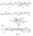
- Fig 2A is a perspective view from one side of a light guide 62a
- Fig 2B is a perspective view of the light guide 62a from the same side, but with the light guide 62a flipped over to show the underside thereof
- Fig 2C is an end view of the light guide 62a viewed in the direction of arrow C in Fig 2A, also showing light guide 62b in ghost line
- Fig 2D is a schematic view of the light guide 62a illustrating how light is coupled into and out of the guide 62a.
- Each light guide 62 is a one-piece moulding from acrylic plastic and includes: a lens portion 66 formed at one end of the guide 62; a full width trunk portion 82; and a half width branch portion 84 extending from the trunk portion 82 to the image sensor 60.
- the branch portion 84 functions as a continuation of the trunk portion 82, although narrower in width, and they share a common sidewall 86.
- a light input coupling 90 extending approximately half-way across the trunk portion width; the remaining width of the trunk portion 82 continues as the branch portion 84.
- the trunk portion 82 is a light guiding portion having a generally cuboid shape.
- the trunk portion 82 has a width (indicated by arrow 92) of approximately 10mm and a height of approximately 10mm.
- the branch portion 84 is also a light guiding portion having a generally cuboid shape with a width (indicated by arrow 94) of approximately 5mm and a height of approximately 10mm.
- the light input coupling 90 includes a lens 96 formed on an underside 98 (see Fig 2B) of the trunk portion 82.
- the coupling 90 also includes a sloping topside 100 for reflecting light from the light source 78 along the trunk portion 82 to the lens 66.
- the branch portion 84 has an imager end 110 in the vicinity of the image sensor 60, which includes a light output coupling 112.
- the light output coupling 112 is similar to the light input coupling 90, and includes a lens 114 formed on an underside 116 (see Fig 2B) of the branch portion 84.
- the coupling 112 also includes a sloping topside 118 for reflecting light propagating from the lens 66 to the image sensor 60.
- Light guide 62b is the mirror image of light guide 62a, which enables the two light guides 62a,b to be placed alongside each other, as shown in Fig 2C.
- light guide 62b includes a light input coupling 190 having a sloping topside 200 corresponding to the light input coupling 90 having a sloping topside 100 of light guide 62a; and light guide 62b includes a light output coupling 212 having a sloping topside 218 corresponding to the light output coupling 112 having a sloping topside 118 of light guide 62a.
- the two light output couplings 112,212 are adjacent each other and are mounted above different portions of the image sensor 60.
- Light output coupling 112 is mounted above portion 60a of image sensor 60, referred to as zone A; and light output coupling 212 is mounted above portion 60b of image sensor 60, referred to as zone B.
- zone A 60a is used to detect the light output from light guide 62a
- zone B is used to detect the light output from light guide 62b.
- Fig 2D illustrates how a light guide 62 functions by referring to light guide 62a, although the skilled person will realize that light guide 62b functions in a very similar way.
- Emitted light (illustrated by unbroken line 130) from light source 78 is coupled into the trunk portion 82 and propagates along the light guide 62a and out through the lens 66 to illuminate a sensing area (indicated by arrow 68).
- Reflected light (illustrated by broken line 134) from the sensing area 68 is coupled into the trunk portion 82 via the lens 66, and propagates along the trunk portion 82 and the branch portion 84, and out through the light output coupling 112 to illuminate the image sensor zone A 60a.
- zone A 60a comprises half of the pixels in the image sensor 60 and zone B 60b comprises the other half of the pixels in the image sensor 60.
- Fig 3A is a graph illustrating light intensity detected across a row of pixels of image sensor 60 at a moment in time.
- the x-axis represents the pixel number
- the y-axis represents the detected light intensity at a pixel number.
- Line 300 indicates the threshold intensity between a white and a black point. If the light intensity detected by a pixel is on or above this threshold 300, then that pixel registers a "white" point; whereas, if the light intensity detected by a pixel is below this threshold, then that pixel registers a "black" point.
- Fig 3B is a schematic diagram illustrating the light output status of the row of pixels shown in Fig 3A.
- three areas 310,312,314 are dark because the light intensity detected by pixels in these areas is below the threshold 300, and two areas 316,318 are light because the light intensity detected by pixels in these areas is above the threshold 300.
- the image sensor 60 includes a hundred rows of pixels, with a hundred and twenty eight pixels in a row, so a complex scene can be imaged.
- This analysis may be for the purpose of determining the position of a moving object and/or to measure properties of an object.
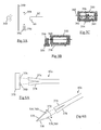
- Fig 4A is a schematic plan diagram illustrating a fixed reference template 330 backlit by a sensing site light source 332 (in the form of a white light LED).
- a light guide 62 is located to gather optical information from the reference template 330 via the lens 66.
- An object 334 to be sensed having a marker portion 336 moves parallel with and relative to the fixed reference template 330, and passes between the reference template 330 and the light guide 62 in the direction of doubleheaded arrow 338.
- the marker portion 336 is used in sensing the position of the object 334.
- Fig 4B is a schematic elevation view of the reference template 330.
- the template 330 is a black plastic sheet defining a rectangular aperture having a width of ten millimetres and a height of twenty millimetres.
- the marker portion 336 has a width of four millimetres and a height of twelve millimetres.
- the absolute dimensions of the aperture and the marker portion are not essential; however, it is important that the width of the marker portion 336 is less than the width of the rectangular aperture.
- the sensing site light source 332 (which is not the same as the light guide light source 78 in Fig 1) is relatively intense so that the light transmitted through the template aperture is much more intense than any ambient light. This ensures that the reference template 330 (except the aperture) looks black and the aperture looks white.
- a scan line 340 is shown to illustrate a line that the image sensor 60 will evaluate to determine if the marker 336 is present.
- Fig 4C is a schematic elevation view of the reference template 330 with the marker portion 336 located in front of the aperture. Because the marker portion 336 has low transmissivity and is considerably narrower than the template aperture, the marker portion 336 is partially silhouetted by the rear light source 332, as shown in Fig 4C. To state this another way, when the marker portion 336 is located in the centre of the aperture, the marker portion 336 appears to be black and surrounded by white light beyond the marker portion's opposing long edges.
- the image sensor 60 uses single threshold analysis to determine whether each pixel in a row corresponding to scan line 340 records high intensity (white light) or low intensity (black). If a sequence of consecutive low intensity pixels is bounded on each side by a relatively small number of high intensity pixels, then this indicates that the marker 336 is located entirely within the aperture, as shown in Fig 4C. Thus, the position of the object 334 can be accurately determined by single threshold analysis using the reference template 330 and the marker portion 336.
- reference template aperture may be used (for example, a square, a triangle, a circle, a rhombus, or such like) to detect different shapes of marker portion. If the object may skew when it moves, then a marker portion shape and reference template aperture shape may be selected to enable the amount of skew to be detected. This may involve multiple scan lines being measured.
- a reference template may include multiple apertures, each aperture may be a different shape, or may be the same shape to track an object as it moves along a path.
- the integration time (shutter time) of the image sensor 60 should be selected so that any features in the background produce a light intensity substantially less than the threshold between high intensity and low intensity.
- the light source 332 should irradiate at an intensity that is substantially above the threshold between high and low intensity. It is preferred that the microprocessor 72 controls the intensity of the light source 332 and the integration time of the image sensor 60 to ensure that the ambient light is detected as very low intensity and the light radiating through the aperture is detected as very high intensity.
- a marker portion within the dispenser 10 may be appropriate for a moving mechanical object, such as a lever, a shutter, a shuttle, a door, or such like.
- the moving mechanical object is aligned when a high intensity signal is recorded on both sides of a low intensity signal.
- Fig 5A is a schematic plan diagram illustrating a backlit extended reference template with an object present.
- the extended reference template 350 is positioned between a sensing site light source 352 and a light guide 62.
- a moving object 354 having a marker portion 356 moves parallel with and relative to the extended reference template 350, and passes between the template 350 and the light guide 62 in the direction of doubleheaded arrow 358.
- the marker portion 356 is used by the sensor in determining the position, direction, and speed of the moving object 354.
- Fig 5B is a schematic elevation view of the extended reference template 350.
- the template 350 is a black plastic sheet defining a rectangular aperture having a width of fifty millimetres and a height of twenty millimetres.
- the marker portion 356 has a width of four millimetres and a height of twelve millimetres.
- a scan line 360 is shown to illustrate a line that the image sensor 60 will evaluate to determine if the marker 356 is present. Any convenient line (represented by a row of pixels in the image sensor 60) can be chosen, provided the line passes through the width of the marker portion 356.
- Fig 5C is a schematic elevation view of the extended reference template 350 with the marker portion 356 located in front of the aperture. Because the marker portion 356 has low transmissivity and is considerably narrower than the aperture width, the marker portion 356 is partially silhouetted by the rear light source 352, as shown in Fig 5C. However, because the aperture is substantially wider than the marker portion 356, single threshold analysis can be used to determine the number of high intensity pixels on one side of the marker 356 (indicated by arrow 362), and the number of high intensity pixels on the opposite side of the marker 356 (indicated by arrow 364).
- the edge of a picked media item is illuminated and the thickness of the media item is measured to validate whether the picked media item really is only a single sheet or if multiple sheets have been inadvertently picked as a single sheet.
- a bifurcated light guide 62c would be provided, as shown in Figs 6A and 6B, at a suitable sensing site.
- One suitable sensing site is in proximity to the pick arm 24 (Fig 1); another suitable site is above the stacking transport 34 (Fig 1).
- a sensing site in proximity to the pick arm 24 is preferred because a picked media item pivots about its long edge when it is picked and moved to the vertical transport 30 (as illustrated in Fig 6B by the media item 370 in full and ghost lines). Pivoting of the media item provides visual access to an upper and lower side of the picked media item.
- a media item 370 (or what is assumed to be an item) is moving in the direction of arrow 372 (Fig 6B).
- the upper fork 374 surveys a first edge area 376
- the lower fork 378 surveys a second edge area 380.
- the first and second edge areas 376,380 each cover a relatively small area (for example a five millimetre by five millimetre vertical plane) through which the picked media item 370 is transported.
- the forks 374,378 view their respective areas 376,380 at a slightly different angle, as best seen in Fig 6B. Furthermore, fork 374 views an upper portion of the media item 370; and fork 378 views a lower portion of the media item 370.
- the same pixels on an image sensor may be used to record an image from each fork 374,378. Viewing the picked media item 370 from each of two angles (preferably, one including the upper portion of the media item and one including the lower portion of the media item), gives greater confidence that one media item is not being obscured by another.
- Each edge area 376,380 is illuminated by an edge illumination light source (not shown). Those parts of the edge areas 376,380 that include an edge of a media item are much brighter than those parts that do not have an edge of a media item.
- the edge illumination light sources are sequentially illuminated so that only one edge area is illuminated at a time. This ensures that the image sensor (not shown) captures image data from only one edge area at a time, with alternate images emanating from the same edge area.
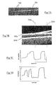
- Figs 7A and 7B are greyscale pictorial views of multiple sheets of media 382 being transported as a single media item.
- Fig 7A shows a long edge of the media, and includes an edge area illustrated by ellipse 384;
- Fig 7B shows a magnified view of the edge area of Fig 7A, and indicates two scan lines 386a,b corresponding to two columns of pixels in an image sensor, such as image sensor 60.
- the light levels and the image sensor integration time are selected so that most of the image appears dark apart from edges of the media items 382; however, a human observer would be able to see clearly the entire media item(s) 382 due to the ambient light level.
- Fig 7C is a graph showing pixel intensity versus pixel number for scan line 386a
- Fig 7D is a graph showing pixel intensity versus pixel number for scan line 386b shown in Fig 7B. Both of these graphs are based on multiple threshold analysis.
- the first threshold is set at approximately 90% of the maximum light level; the second threshold is set at approximately 70% of the maximum light level.
- the 70% level corresponds to strong light emitted from approximately 5mm behind the media item edge, which provides a 5mm depth of field. This means that any media item located adjacent another media item and having an edge less than 5mm behind the edge of that other media item will be detected at the second threshold level.
- first line 382a that is substantially thicker than a second line 382b.
- this thicker line 382a corresponds to two media items, and not, for example, a fold at an end of one media item.
- both scan lines 386a,b cover an image conveyed from a single light guide, or a single fork of a bifurcated light guide; however, images from different forks of a light guide may be required to be confident that two media items are present, that is, to be able to resolve two separate peaks rather than one broad peak. It will also be understood that multiple thresholds may be used (many more than two) to determine if multiple media items are present.
- Additional media items may be present outside the focal depth of the sensor (in this example, more than 5mm behind the leading edge), but these media items may be detected at other positions in the dispenser 10, such as the stacking wheel 36 (Fig 1).
- Fig 8 illustrates an object 390 having two markings 392a,b in the form of dark dots spaced a predetermined known distance apart, in this example 5cm.
- the object 390 has a reflective surface on which the dots 392 are placed.
- the distance from the sensor 60 to the object By applying two dark dots (or any other markings) to a reflective object, where the dots are separated by a known distance, it is possible to compute the distance from the sensor 60 to the object by measuring the apparent distance between the dots. For example, if the apparent separation between the dots is 4.3cm, then the distance between the dots and the sensor 60 is approximately 15cm; if the apparent separation between the dots is 2cm, then the distance between the dots and the sensor 60 is approximately 30cm.
- the apparent distance between the dots can be measured using single threshold analysis, and counting the number of high intensity pixels between the two low intensity dots. A mapping of pixels to distance can easily be prepared.
- light guide 62a illuminates the pick module 12 and conveys reflected light back to zone A 60a of the image sensor 60.
- the processor 72 continually analyses the zone A pixels 60a to determine the alignment of the pick arm 24 and the location of any picked notes within the module 12.
- the processor firmware is pre-programmed so that the processor 72 can determine which pixels are related to which object to be detected.
- the firmware contains a mapping of the objects to be detected with the pixels in the image sensor 60.
- the pick arm 24 may be associated with pixels in rows one to twelve and columns one to twenty. By analysing the pixels in rows one to twelve and columns one to twenty, the processor 72 can determine the position of the pick arm 24.
- Light guide 62b illuminates the presenter module 14 and conveys reflected light back to zone B 60b of the image sensor 60.
- the processor 72 continually analyses the zone B pixels 60b to determine the alignment of the moving parts within the module, for example, the stacking transport 34, the stacking wheel 36, the purge transport 40, the clamping transport 44, and the location of any picked notes within the module 14.
- Each moving part has a unique group of pixels permanently associated therewith, so the processor 72 analyses a particular group of pixels to determine the location of a particular moving part associated with that group of pixels.
- a processor 72 determines that a picked banknote is skewing as it is moving up the vertical transport 30, then the processor 72 can monitor the banknote as it enters the stacking transport 34 to determine if the skew is increasing or reducing as it is transported. If the skew is increasing, then the processor 72 activates motors (not shown) within the presenter module 14 to purge the skewed banknote to the purge bin 42.
- the light guide 62b serves as a note thickness sensor. This is achieved by the image sensor 60 recording an image of the thickness of a picked banknote as it is being transported up the stacking transport 34.
- the processor 72 analyses this image to determine the thickness of the banknote and to compare the measured thickness with the nominal thickness of a banknote. If the measured thickness exceeds the nominal thickness by more than a predetermined amount (for example, five per cent), then the processor 72 either activates the presenter module 14 to purge the measured banknote to the purge bin 42, or continues transporting the picked note if the processor 72 can determine how many notes are present.
- a predetermined amount for example, five per cent
- the light guide 62b also serves as a bunch thickness sensor. This is achieved by the image sensor 60 recording an image of the thickness of a bunch of banknotes as they are presented to a user at the exit aperture 48.
- the processor 72 analyses this image to determine the thickness of the bunch before it is presented, and after it is retracted (if it is not removed by the user). If the thickness of the bunch before presentation differs from the thickness of the bunch after retraction by more than a predetermined amount (for example, two per cent), then the processor 72 activates the presenter module 14 to purge the measured banknote to the purge bin 42 and records that the retracted bunch contained fewer notes than the presented bunch. The processor 72 may record how many fewer notes were retracted than presented.
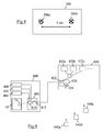
- Fig 9 is a simplified block diagram illustrating an ATM 400 including the dispenser 10.
- the ATM 400 includes a PC core 402, which controls the operation of peripherals within the ATM 400, such as the dispenser 10, a display 404, a card reader 406, an encrypting keypad 408, and such like.
- the PC core 402 includes a USB port 410 for communicating with the USB port 76 in the dispenser 10.
- the PC core 402 includes an Ethernet card 412 for communicating across a network to a remote server 420.
- the server 420 has an Ethernet card 422 and is located within a diagnostic centre 430.
- the server 420 receives captured image data from ATMs, such as ATM 400.
- the image data can be collated and displayed as a sequence of images.
- the diagnostic centre 430 includes a plurality of terminals 432 interconnected to the server 420 for monitoring the operation of a large number of such ATMs.
- the server 420 includes a wireless communication card 434 for communicating with wireless portable field engineer devices 440. These devices 440 are similar to portable digital assistants (PDAs).
- PDAs portable digital assistants
- the server 420 is a Web server allowing password protected access to authorised personnel, such as field engineers issued with the field engineer devices 440, and human agents operating the terminals 432.
- the USB port 76 on the control board 70 transmits image data (in the form of eight bit digital outputs) from the sensor 60 to the PC core 402 located in ATM 400.
- the PC core 402 transmits the received image data to the Web server 420, thereby enabling operators at the terminals 432 and field engineers to view the captured data by accessing the Web server 420.
- the Web server 420 may further process the captured images. Such further processing may include analysing the captured images to determine patterns emerging prior to a failure arising in the dispenser. This information may be used to predict and avoid similar failures in the future. Field engineers and terminal operators may access these captured images to determine if the dispenser 10 is operating correctly.
- an optical image sensor can be used to replace a large number of individual sensors, and can provide more detailed information than was previously available using individual sensors.
- the media items were currency items; whereas, in other embodiments financial documents, such as cheques, Giros, invoices, and such like may be handled.
- media items other than currency or financial documents may be dispensed, for example a booklet of stamps, a telephone card, a magnetic stripe card, an integrated circuit or hybrid card, or such like.
- a dispenser may have one or more cassettes containing currency, and one or more cassettes storing another type of media item capable of being removed by a pick unit.
- the imaging device may be located on a control board, in the pick module, or in some other convenient location.
- the lens portion may be separate from but coupled to the light guide.
- each moving part has a unique group of pixels permanently associated therewith; however, in other embodiments, this may not be the case.
- any convenient template colour or material may be used.
- the light source used to backlight the reference template may be of any convenient wavelength, although visible wavelengths are preferred as this enables a person to view the measurements, if desired.
- each pick module may use two backlight sources, and the presenter module may use five backlight sources; although the number of backlight sources used will vary depending on the number and types of objects to be detected.
Landscapes
- Physics & Mathematics (AREA)
- General Physics & Mathematics (AREA)
- Testing Of Coins (AREA)
- Investigating Or Analysing Materials By Optical Means (AREA)
- Image Input (AREA)
Applications Claiming Priority (2)
| Application Number | Priority Date | Filing Date | Title |
|---|---|---|---|
| GBGB0329595.3A GB0329595D0 (en) | 2003-12-20 | 2003-12-20 | Sensing arrangement |
| GB0329595 | 2003-12-20 |
Publications (2)
| Publication Number | Publication Date |
|---|---|
| EP1548662A2 true EP1548662A2 (fr) | 2005-06-29 |
| EP1548662A3 EP1548662A3 (fr) | 2006-06-14 |
Family
ID=30776217
Family Applications (1)
| Application Number | Title | Priority Date | Filing Date |
|---|---|---|---|
| EP04256774A Withdrawn EP1548662A3 (fr) | 2003-12-20 | 2004-11-03 | Ensemble capteur |
Country Status (3)
| Country | Link |
|---|---|
| US (1) | US7638746B2 (fr) |
| EP (1) | EP1548662A3 (fr) |
| GB (1) | GB0329595D0 (fr) |
Cited By (4)
| Publication number | Priority date | Publication date | Assignee | Title |
|---|---|---|---|---|
| EP1635301A3 (fr) * | 2004-09-14 | 2006-11-02 | NRC International Inc. | Dispositif capteur |
| DE102008003917A1 (de) * | 2008-01-10 | 2009-07-16 | Wincor Nixdorf International Gmbh | Vorrichtung und Verfahren zur Füllstandsmessung in einem Wertbehälter zur Aufnahme von Wertscheinen |
| EP2058773A3 (fr) * | 2007-11-07 | 2009-11-04 | Hitachi-Omron Terminal Solutions, Corp. | Dispositif de manipulation de feuilles |
| EP2960877A1 (fr) * | 2014-06-23 | 2015-12-30 | NCR Corporation | Distributeur de supports de valeur |
Families Citing this family (17)
| Publication number | Priority date | Publication date | Assignee | Title |
|---|---|---|---|---|
| US8573481B1 (en) * | 2007-11-13 | 2013-11-05 | Diebold Self-Service Systems Division Of Diebold, Incorporated | Banking system controlled responsive to data bearing records |
| GB0328723D0 (en) * | 2003-12-11 | 2004-01-14 | Ncr Int Inc | Self-service terminal |
| WO2013027848A1 (fr) * | 2011-08-25 | 2013-02-28 | グローリー株式会社 | Dispositif d'identification d'article papier, guide optique de spectrométrie d'article papier et boîtier de guide optique |
| US8985298B2 (en) | 2013-05-09 | 2015-03-24 | Bank Of America Corporation | Dual validator self-service kiosk |
| US9747588B2 (en) | 2013-05-09 | 2017-08-29 | Bank Of America Corporation | Automated teller machine (“ATM”) currency stamper |
| US9368002B2 (en) | 2013-05-09 | 2016-06-14 | Bank Of America Corporation | Sensor system for detection of a partial retrieval of dispensed currency at an automated teller machine |
| US9038805B2 (en) | 2013-05-09 | 2015-05-26 | Bank Of America Corporation | Self-service kiosk validator bridge |
| US9251672B2 (en) | 2013-05-20 | 2016-02-02 | Bank Of America Corporation | Stacking purge-bin |
| US9163978B2 (en) | 2013-05-20 | 2015-10-20 | Bank Of America Corporation | Purge-bin weighing scale |
| KR101492406B1 (ko) * | 2013-09-06 | 2015-02-16 | 기산전자 주식회사 | 지폐처리장치의 상태 분석 및 예측 시스템과 그 계층 구조 |
| GB2517983B (en) * | 2013-09-09 | 2016-03-16 | Ibm | Security apparatus for an automated teller machine |
| DE202015101489U1 (de) * | 2015-03-24 | 2016-06-28 | Crane Payment Innovations Gmbh | Vorrichtung zur Bestimmung des Füllstands von Münztuben |
| GB2552026B (en) | 2016-07-08 | 2020-06-10 | Ibm | Shutter assembly for an automated teller machine |
| US10380662B2 (en) * | 2016-08-30 | 2019-08-13 | Ncr Corporation | Pre-verification processing |
| US10249150B1 (en) | 2017-10-03 | 2019-04-02 | International Business Machines Corporation | Security apparatus for an automated teller machine |
| US10109160B1 (en) | 2017-10-03 | 2018-10-23 | International Business Machines Corporation | Shutter assembly for an automated teller machine |
| DE102020207365A1 (de) * | 2020-06-15 | 2021-12-16 | Siemens Healthcare Gmbh | Einfädelunterstützungseinrichtung zum Einfädeln eines Objektes in eine Führungsvorrichtung |
Family Cites Families (19)
| Publication number | Priority date | Publication date | Assignee | Title |
|---|---|---|---|---|
| FR2122040A6 (fr) * | 1971-01-15 | 1972-08-25 | Compteurs Comp D | |
| FR2218599A1 (fr) * | 1973-02-16 | 1974-09-13 | Schlumberger Compteurs | |
| EP0072236B1 (fr) * | 1981-08-11 | 1987-07-15 | De La Rue Systems Limited | Appareil pour détecter la présence de ruban adhésif sur des documents |
| DE3275773D1 (en) * | 1981-11-03 | 1987-04-23 | De La Rue Syst | Apparatus for sorting sheets according to their patterns |
| GB2109923B (en) * | 1981-11-13 | 1985-05-22 | De La Rue Syst | Optical scanner |
| GB2228817A (en) * | 1989-03-03 | 1990-09-05 | Unisys Corp | Document imaging apparatus |
| CH689523A5 (de) * | 1989-05-01 | 1999-05-31 | Mars Inc | Pruefeinrichtung fuer ein blattfoermiges Gut. |
| US5086220A (en) * | 1991-02-05 | 1992-02-04 | The Babcock & Wilcox Company | Radiation imaging fiber optic temperature distribution monitor |
| US5389789A (en) * | 1992-05-20 | 1995-02-14 | Union Camp Corporation | Portable edge crack detector for detecting size and shape of a crack and a portable edge detector |
| JPH06208613A (ja) * | 1992-11-13 | 1994-07-26 | Laurel Bank Mach Co Ltd | パターン検出装置 |
| JP2609048B2 (ja) * | 1993-07-12 | 1997-05-14 | 沖電気工業株式会社 | 搬送媒体の検出装置 |
| US5534690A (en) * | 1995-01-19 | 1996-07-09 | Goldenberg; Lior | Methods and apparatus for counting thin stacked objects |
| JP2972116B2 (ja) | 1995-05-15 | 1999-11-08 | 三菱電機ビルテクノサービス株式会社 | 指紋照合装置 |
| US5699448A (en) * | 1995-07-05 | 1997-12-16 | Universal Instruments Corporation | Split field optics for locating multiple components |
| GB2309299B (en) * | 1996-01-16 | 2000-06-07 | Mars Inc | Sensing device |
| US5828724A (en) * | 1997-03-25 | 1998-10-27 | Advanced Technology Materials, Inc. | Photo-sensor fiber-optic stress analysis system |
| IT1299838B1 (it) * | 1998-02-12 | 2000-04-04 | Gd Spa | Dispositivo ottico di controllo di presenza. |
| WO2001001112A1 (fr) | 1999-06-26 | 2001-01-04 | Packard Instrument Company, Inc. | Lecteur pour microplaques |
| GB9915034D0 (en) | 1999-06-29 | 1999-08-25 | Cambridge Imaging Ltd | Improved assay analysis |
-
2003
- 2003-12-20 GB GBGB0329595.3A patent/GB0329595D0/en not_active Ceased
-
2004
- 2004-11-03 EP EP04256774A patent/EP1548662A3/fr not_active Withdrawn
- 2004-12-17 US US11/016,661 patent/US7638746B2/en not_active Expired - Lifetime
Non-Patent Citations (1)
| Title |
|---|
| None * |
Cited By (7)
| Publication number | Priority date | Publication date | Assignee | Title |
|---|---|---|---|---|
| EP1635301A3 (fr) * | 2004-09-14 | 2006-11-02 | NRC International Inc. | Dispositif capteur |
| US7230223B2 (en) | 2004-09-14 | 2007-06-12 | Ncr Corporation | Sensing system for ascertaining currency content of ATM |
| EP2058773A3 (fr) * | 2007-11-07 | 2009-11-04 | Hitachi-Omron Terminal Solutions, Corp. | Dispositif de manipulation de feuilles |
| US8246046B2 (en) | 2007-11-07 | 2012-08-21 | Hitachi-Omron Terminal Solutions, Corp. | Sheet handling device |
| DE102008003917A1 (de) * | 2008-01-10 | 2009-07-16 | Wincor Nixdorf International Gmbh | Vorrichtung und Verfahren zur Füllstandsmessung in einem Wertbehälter zur Aufnahme von Wertscheinen |
| DE102008003917B4 (de) | 2008-01-10 | 2022-06-30 | Wincor Nixdorf International Gmbh | Vorrichtung und Verfahren zur Füllstandsmessung in einem Wertbehälter zur Aufnahme von Wertscheinen |
| EP2960877A1 (fr) * | 2014-06-23 | 2015-12-30 | NCR Corporation | Distributeur de supports de valeur |
Also Published As
| Publication number | Publication date |
|---|---|
| GB0329595D0 (en) | 2004-01-28 |
| EP1548662A3 (fr) | 2006-06-14 |
| US20050173659A1 (en) | 2005-08-11 |
| US7638746B2 (en) | 2009-12-29 |
Similar Documents
| Publication | Publication Date | Title |
|---|---|---|
| US7638746B2 (en) | Sensing system for detecting whether one bill, or more than one bill, is present at a sensing station in an ATM | |
| RU2488886C2 (ru) | Определение пригодности документов с использованием чередующегося освещения | |
| US9978196B2 (en) | Banknote acceptor with visual checking | |
| US7230223B2 (en) | Sensing system for ascertaining currency content of ATM | |
| US20080273789A1 (en) | Acceptor Device for Sheet Objects | |
| JP2012198188A (ja) | 光検出装置、及び光検出装置を備える紙葉類処理装置 | |
| KR100711689B1 (ko) | 지폐 감별 장치 | |
| JP4703403B2 (ja) | 検査装置 | |
| US6257389B1 (en) | Device for examining securities | |
| KR20070068293A (ko) | 시트 처리 방법 및 시트 처리 장치 | |
| WO2009066297A2 (fr) | Procédé de vérification du contenu de liasses de papier-monnaie | |
| KR20130094391A (ko) | 매체 인식 장치 및 금융기기 | |
| KR200394238Y1 (ko) | 지폐 계수 겸용 고속 스캐너 | |
| EP2743894A1 (fr) | Détection de supports de contrefaçon | |
| US20090294244A1 (en) | Currency Validator with Rejected Bill Image Storage | |
| CN108604397B (zh) | 有价票券处理装置及有价票券处理方法 | |
| KR101397791B1 (ko) | 매체 인식 장치 및 금융기기 | |
| GB2444966A (en) | Validating sheet objects with a barcode and money value | |
| JP2010073048A (ja) | 紙葉類処理装置、及び、紙葉類処理方法 | |
| US8126251B2 (en) | Photo sensor array for banknote evaluation | |
| EP1510977B1 (fr) | Appareil pour la détection de l'inclinaison d'un document | |
| JP6601000B2 (ja) | 紙幣鑑別装置、自動取引装置、調整治具取付方法、及び調整治具 | |
| WO2012051933A1 (fr) | Machine de transactions financières intelligente | |
| JP2004185447A (ja) | 紙幣識別装置及び紙幣処理装置 | |
| JP2012168864A (ja) | 切れ検出装置、及び切れ検出装置を備える紙葉類処理装置 |
Legal Events
| Date | Code | Title | Description |
|---|---|---|---|
| PUAI | Public reference made under article 153(3) epc to a published international application that has entered the european phase |
Free format text: ORIGINAL CODE: 0009012 |
|
| AK | Designated contracting states |
Kind code of ref document: A2 Designated state(s): AT BE BG CH CY CZ DE DK EE ES FI FR GB GR HU IE IS IT LI LU MC NL PL PT RO SE SI SK TR |
|
| AX | Request for extension of the european patent |
Extension state: AL HR LT LV MK YU |
|
| PUAL | Search report despatched |
Free format text: ORIGINAL CODE: 0009013 |
|
| AK | Designated contracting states |
Kind code of ref document: A3 Designated state(s): AT BE BG CH CY CZ DE DK EE ES FI FR GB GR HU IE IS IT LI LU MC NL PL PT RO SE SI SK TR |
|
| AX | Request for extension of the european patent |
Extension state: AL HR LT LV MK YU |
|
| 17P | Request for examination filed |
Effective date: 20061214 |
|
| 17Q | First examination report despatched |
Effective date: 20070118 |
|
| AKX | Designation fees paid |
Designated state(s): DE ES FR GB IT |
|
| STAA | Information on the status of an ep patent application or granted ep patent |
Free format text: STATUS: THE APPLICATION HAS BEEN WITHDRAWN |
|
| 18W | Application withdrawn |
Effective date: 20070619 |