EP1548522A2 - Fixing apparatus and image inputting apparatus - Google Patents
Fixing apparatus and image inputting apparatus Download PDFInfo
- Publication number
- EP1548522A2 EP1548522A2 EP04106901A EP04106901A EP1548522A2 EP 1548522 A2 EP1548522 A2 EP 1548522A2 EP 04106901 A EP04106901 A EP 04106901A EP 04106901 A EP04106901 A EP 04106901A EP 1548522 A2 EP1548522 A2 EP 1548522A2
- Authority
- EP
- European Patent Office
- Prior art keywords
- recording medium
- fixing
- controller
- pressing force
- pressing mechanism
- Prior art date
- Legal status (The legal status is an assumption and is not a legal conclusion. Google has not performed a legal analysis and makes no representation as to the accuracy of the status listed.)
- Granted
Links
- 238000003825 pressing Methods 0.000 claims abstract description 125
- 238000009826 distribution Methods 0.000 claims abstract description 37
- 238000010438 heat treatment Methods 0.000 claims abstract description 28
- 230000007613 environmental effect Effects 0.000 claims description 6
- 230000004048 modification Effects 0.000 description 6
- 238000012986 modification Methods 0.000 description 6
- 239000000463 material Substances 0.000 description 4
- 230000006835 compression Effects 0.000 description 3
- 238000007906 compression Methods 0.000 description 3
- 238000001514 detection method Methods 0.000 description 3
- 238000000034 method Methods 0.000 description 3
- 230000004323 axial length Effects 0.000 description 2
- 230000007423 decrease Effects 0.000 description 2
- 239000010410 layer Substances 0.000 description 2
- 230000000903 blocking effect Effects 0.000 description 1
- 239000011248 coating agent Substances 0.000 description 1
- 239000011247 coating layer Substances 0.000 description 1
- 238000000576 coating method Methods 0.000 description 1
- 239000003086 colorant Substances 0.000 description 1
- 238000010276 construction Methods 0.000 description 1
- 230000006866 deterioration Effects 0.000 description 1
- 230000001627 detrimental effect Effects 0.000 description 1
- 238000002474 experimental method Methods 0.000 description 1
- 238000004519 manufacturing process Methods 0.000 description 1
- 239000002184 metal Substances 0.000 description 1
- 230000002093 peripheral effect Effects 0.000 description 1
- 238000009827 uniform distribution Methods 0.000 description 1
Images


Classifications
-
- G—PHYSICS
- G03—PHOTOGRAPHY; CINEMATOGRAPHY; ANALOGOUS TECHNIQUES USING WAVES OTHER THAN OPTICAL WAVES; ELECTROGRAPHY; HOLOGRAPHY
- G03G—ELECTROGRAPHY; ELECTROPHOTOGRAPHY; MAGNETOGRAPHY
- G03G15/00—Apparatus for electrographic processes using a charge pattern
- G03G15/20—Apparatus for electrographic processes using a charge pattern for fixing, e.g. by using heat
- G03G15/2003—Apparatus for electrographic processes using a charge pattern for fixing, e.g. by using heat using heat
- G03G15/2014—Apparatus for electrographic processes using a charge pattern for fixing, e.g. by using heat using heat using contact heat
- G03G15/2064—Apparatus for electrographic processes using a charge pattern for fixing, e.g. by using heat using heat using contact heat combined with pressure
-
- G—PHYSICS
- G03—PHOTOGRAPHY; CINEMATOGRAPHY; ANALOGOUS TECHNIQUES USING WAVES OTHER THAN OPTICAL WAVES; ELECTROGRAPHY; HOLOGRAPHY
- G03G—ELECTROGRAPHY; ELECTROPHOTOGRAPHY; MAGNETOGRAPHY
- G03G2215/00—Apparatus for electrophotographic processes
- G03G2215/00362—Apparatus for electrophotographic processes relating to the copy medium handling
- G03G2215/00535—Stable handling of copy medium
- G03G2215/00717—Detection of physical properties
- G03G2215/00734—Detection of physical properties of sheet size
-
- G—PHYSICS
- G03—PHOTOGRAPHY; CINEMATOGRAPHY; ANALOGOUS TECHNIQUES USING WAVES OTHER THAN OPTICAL WAVES; ELECTROGRAPHY; HOLOGRAPHY
- G03G—ELECTROGRAPHY; ELECTROPHOTOGRAPHY; MAGNETOGRAPHY
- G03G2215/00—Apparatus for electrophotographic processes
- G03G2215/00362—Apparatus for electrophotographic processes relating to the copy medium handling
- G03G2215/00535—Stable handling of copy medium
- G03G2215/00717—Detection of physical properties
- G03G2215/00776—Detection of physical properties of humidity or moisture influencing copy sheet handling
-
- G—PHYSICS
- G03—PHOTOGRAPHY; CINEMATOGRAPHY; ANALOGOUS TECHNIQUES USING WAVES OTHER THAN OPTICAL WAVES; ELECTROGRAPHY; HOLOGRAPHY
- G03G—ELECTROGRAPHY; ELECTROPHOTOGRAPHY; MAGNETOGRAPHY
- G03G2215/00—Apparatus for electrophotographic processes
- G03G2215/20—Details of the fixing device or porcess
- G03G2215/2003—Structural features of the fixing device
- G03G2215/2009—Pressure belt
Definitions
- the present invention relates to a fixing apparatus and an image-forming apparatus.
- image-forming apparatus a printer, a copying machine, and a facsimile machine that use an electrophotographic image-forming process.
- Such an image-forming apparatus is equipped with a fixing unit in which a toner image deposited on a recording medium is fused into a permanent image.
- the fixing unit includes a heat roller having a built-in heater therein, a pressure pad that opposes the heat roller, and a fixing belt that is sandwiched between the heat roller and the pressure pad and pressed against the heat roller by the pressure pad.
- the pressure pad presses the fixing belt against the heat roller to create a nip between the fixing belt and the heat roller.
- the aforementioned conventional fixing unit suffers from the problem that the nip region is difficult to be uniform for different types of recording medium and non-uniform nips cause poor print quality.
- the present invention was made in view of the aforementioned problems.
- An object of the invention is to provide a fixing apparatus and an image-forming apparatus where a uniform nip can be formed to improve image quality.
- a fixing apparatus operates to fix a toner image on a recording medium.
- a heating member (11) extends in a first direction transverse to a second direction in which a recording medium travels for fixing.
- a belt (28) contacts the heater member (11) to form a fixing region (N) between the belt and the heating member (11).
- a pressure member (14, 34) presses the belt (28) against the heating member (11) .
- a pressing mechanism (13, M1-M8) engages the pressure member (11) to apply a predetermined pressure to the pressure member (11) toward the fixing region (N) in such a way that the pressure has an adjustable profile of distribution in the first direction.
- the pressing mechanism (13, M1-M8) is a rotatable member (13) that extends in a third direction substantially parallel to the first direction.
- the rotatable member (13) has a surface (13a, 13b, 13c, 13d) that is brought into contact engagement with the pressure member (14, 34) when the rotatable member (13) is rotated, the surface has a predetermined profile of geometry in the third direction such that the pressing force has the predetermined profile of distribution in the first direction.
- the fixing apparatus may further include a deformable resilient member (38) disposed between the pressing mechanism (M1-M8) and the pressure member (14, 34) , the deformable resilient member (38) extending in a direction generally parallel to the first direction.
- the pressing mechanism (M1-M8) includes a plurality of sub-mechanisms (M1-M8) aligned in a direction generally parallel to the first direction.
- the plurality of sub-mechanisms (M1-M8) are adjustable independently so that each of the plurality of sub-mechanisms applies different amounts of force to the pressure member.
- An image-forming apparatus has a fixing apparatus.
- the fixing apparatus includes:
- the pressing mechanism (13) of the image-forming apparatus is rotatable and extends in a third direction substantially parallel to the first direction, wherein the pressing mechanism (13) has a surface (13a, 13b, 13c, 13d) that is brought into contact engagement with the pressure member (14, 34) to apply a pressing force to the pressure member toward the fixing when the rotatable member is rotated, the surface having a predetermined profile of geometry in the third direction such that the pressing force has the predetermined profile of distribution in the first direction.
- the fixing apparatus of the image-forming apparatus further includes a deformable resilient member (38) disposed between the pressing mechanism (M1-M8) and the pressure member (14, 34), the deformable resilient member (38) extending in a direction generally parallel to the first direction.
- the pressing mechanism (M1-M8) of the image-forming apparatus includes a plurality of sub-mechanisms (M1-M8) aligned in a direction generally parallel to the first direction.
- the plurality of sub-mechanisms (M1-M8) are adjustable independently so that each of the plurality of sub-mechanisms applies different amounts of force to the pressure member.
- the controller (26) drives the plurality of sub-mechanisms (M1-M8) in accordance with information on the recording medium.
- the controller (26) drives the plurality of sub-mechanisms (M1-M8) in accordance with at least one of environmental temperature and humidity.
- the controller (26) determines a print duty based on image data that should be printed on the recording medium, the controller (26) adjusting the profile of distribution in accordance with the print duty.
- a fixing apparatus includes:
- An image-forming apparatus incorporates the aforementioned fixing apparatus.
- the image-forming apparatus includes a controller (26) that drives the pressing mechanism (13, M1-M8) to adjust the pressing force in such a way that the pressing force has a predetermined profile of distribution in the third direction.
- a printer will be described as an example of an image forming apparatus.
- Fig. 1A is a cross-sectional view of a fixing unit according to a first embodiment.
- Fig. 1B illustrates a partial expanded view of Fig. 1A.
- Fig. 2 is a cross-sectional view taken along line X-X of Fig. 1A.
- a heat roller 11 includes a core metal 11a with a resilient layer 11b formed on it and a coating layer 11c formed on the resilient layer 11b.
- the heat roller 11 incorporates a heater 12 as a built-in heater and is supported at opposite longitudinal end portions by bearings 19.
- a controller 26 (Fig. 3) performs a heating operation in which the heater 12 is energized to heat the heat roller 11 to a predetermined temperature. Then, the controller 26 drives a motor 22 (Fig. 3) that drives the fixing unit, thereby causing the heat roller 11 to rotate at a predetermined speed.
- a thermistor is in contact with the outer circumferential surface of the heat roller 11 to detect the temperature of the circumferential surface.
- Fig. 1B is an enlarged view of a pertinent portion of Fig. 1A.
- a cam 13 is disposed under a pressure pad 14 and rotatably supported on bearings 20.
- the cam 13 is rotatable about an axis Q in directions shown by arrows B and C.
- the cam 13 has a cam surface 13a that applies pressure against the pressure pad 14 when the cam surface engages the pressure pad 14 as shown in Fig. 1A.
- the cam surface has a radius of curvature r , as shown in Fig. 1B.
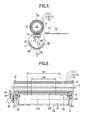
- the cam 13 also has another cam surface 13b that applies pressure against the pressure pad 14 when the cam surface 13b engages the pressure pad 14 as shown in Fig. 5.
- the cam surface 13b are at diametrically opposite side of the cam 13 from the cam surface 13a.
- the cam surfaces 13a and 13b extend in their longitudinal direction and in their circumferential direction.
- the cam 13 is designed to have distances a, b, and c such that a ⁇ b ⁇ c.
- the cam 13 has one end to which a circular light-blocking disk 23 is attached.
- the circular light-blocking disk has a slit 23a (Fig. 3) formed in its circumferential peripheral portion.
- the light-blocking disk 23 is disposed in such a way that when the light blocking disk 23 rotates, the slit 23a rotates into and out of a light path of a position detector 24.
- the cam 13 has a gear 21a mounted near the light-blocking plate 23 that is in mesh with a gear 21b.
- the gear 21b is mounted on a shaft of a pulse motor 22. The rotation of the pulse motor 22 is transmitted to the cam 13 via a gear train formed of the gears 21a and 21b.
- the pressure pad 14 is made of a resilient, heat-resistive material.
- the pressure pad 14 opposes the heat roller 11 and extends in a direction parallel to the longitudinal axis of the heat roller 11.
- the pressure pad 14 has a rectangular cross-section.
- the cam 13 rotates to a position shown in Fig. 1A, the cam surface applies a predetermined pressing force to the pressure pad 14 and the pressure pad 14 is resiliently deformed accordingly as shown in Fig. 1A, thereby transmitting the pressing force to the heat roller 11.
- Supporting members 15 on a body of the printer firmly support the pressure pad 14 at longitudinal ends of the pressure pad 14.
- a belt guide 17 has an arcuate cross section and is disposed under the pressure pad 14.
- a fixing belt 28 is an endless belt and forms a nip N (i.e., fixing region) between the fixing belt 28 and the heat roller 11.
- the fixing belt 28 runs in a loop-like path, which surrounds the pressure pad 14, can shaft 13, and belt guide 17 and passes between the heat roller 11 and the pressure pad 14.
- the pressure pad 14 presses the heat roller 11 with the fixing belt 28 sandwiched therebetween.
- the pressure pad 14, cam 13, belt guide 17 and fixing belt 28 form a fixing unit.
- the pressure pad 14 receives a pressing force from the cam 13 to press the fixing belt 28 against the heat roller 11, thereby creating a nip N between the heat roller 11 and the fixing belt 28.
- the nip forms a fixing region through which a recording medium passes for fixing.
- the pressure pad 14 is deformed by a pressing force such that the nip N is an arcuate recess formed therein that faces the heat roller 11.
- the pressure pad 14 may have a pre-shaped arcuate recess configured to the outer circumferential surface of the heat roller 11. The pre-shaped arcuate recess provides a reliable shape of the nip N.
- a paper-feeding section feeds the recording medium 29 from a paper cassette.
- the recording medium 29 is then advanced by feeding rollers, not shown, through yellow, magenta, cyan, and black image-forming sections, not shown, in sequence.
- Each image-forming section receives image data of a corresponding color from the host apparatus and forms a toner image of the corresponding color.
- the toner images of corresponding colors are transferred onto the recording medium 29 one over the other in sequence, creating a full-color toner image.
- the cam 13 is positioned so that the cam surface 13a or 13b applies a minimum sufficient pressing force to the pressure pad 14. A minimum sufficient pressing force is applied to the pressure pad 14, thereby preventing permanent deformation and deterioration of the heat roller 11 and pressure pad 14 due to the heat received from the heater 12 and the pressure applied through the pressure pad 14.
- Fig. 3 is a schematic perspective view illustrating a nip-adjusting unit according to the first embodiment.
- a setting section 27 stores the number of pulses that are used to drive the pulse motor 22 to rotate.
- the controller 26 drives the pulse motor 22 in rotation so that when the slit 23a enters the light path of the position detector 24, the position detector 24 generates a sensor output.
- the sensor output is sent to a detector 25.
- the detector 25 provides a detection signal to the controller 26, the detection signal indicating that the cam 13 is at a predetermined reference position (Fig. 3) .
- the controller 26 causes the pulse motor 22 to stop at the predetermined reference position where the cam 13 exerts the smallest pressure on the pressure pad 14.
- the controller 26 performs a pressure distribution adjusting operation.
- the controller 26 supplies a predetermined number of pulses to the pulse motor 22 and the pulse motor 22 drives the cam 13 to rotate through an angle corresponding to the number of pulses specified from the setting section 27.
- a predetermined profile of distribution of pressing force can be set across the length of the heat roller 11 by means of the cam surfaces 13a and 13b.
- the controller 26 When the printer receives information on the recording medium 29 such as size, thickness, shape, and material, the controller 26 provides a predetermined number of pulses to the pulse motor 22. In accordance with the predetermined number of pulses, the pulse motor rotates the cam 13 from the reference rotational position to a rotational position shown in Figs. 1 and 2. Thus, the cam surface 13a of the cam 13 applies a pressing force to the pressure pad 14, thereby transmitting a pressing force to the heat roller 11 with a desired profile of distribution across the length of the cam 13.
- the position of the cam 13 is at the angular position in Figs. 1 and 2. This angular position of the cam 13 is referred to as "ORDINARY PAPER position" in the present embodiment.
- the controller 26 drives the motor to rotate the heat roller 11 at a predetermined rotational speed, so that the fixing belt 28 runs to maintain the entire surfaces of the heat roller 11 and fixing belt 28 at a uniform temperature.
- the cam 13 is rotated before the heat roller 11 begins to rotate so that the nip is created concurrently with the image-forming processes of the respective image-forming sections.
- This operation not only shortens the time required for printing but also transmits a pressing force to the heat roller 11, the pressing force having the same profile of distribution as in an actual fixing operation.
- This operation allows preheating of the heat roller 11 and fixing belt 28 to a stable, high temperature at the nip N.
- the cam 13 can be rotated to create an appropriate nip N at any timing before the recording medium 29 reaches the nip N.
- the toner image 18 is heated at a predetermined temperature so that the toner image 18 is fused into the recording medium 29 under an appropriate pressure.
- Fig. 4 illustrates the relation between the axial length of a heat roller and the pressure exerted on the heat roller.
- the pressing force exerted on the heat roller 11 is substantially uniform across the entire length of the heat roller 11 as shown in Fig. 4. This ensures reliable fixing results.
- the pressing force in Fig. 4 is exerted on the entire width of the nip N.
- a recording medium is, for example, an envelope bonded at the same locations and having the same width W but different thicknesses at different locations.
- Such a recording medium can be fixed reliably.
- Elements having similar configurations as those in Figs. 1 and 2 have been given the same reference numerals, and the description thereof is omitted.
- Fig. 5 is a cross-sectional view of the fixing unit according to the first embodiment.
- Fig. 6 is a cross-sectional view taken along line Y-Y of Fig. 5.
- the heater 12 Upon a print command from the host apparatus, the heater 12 begins to heat the heat roller 11. If a recording medium 30 is an envelope, the recording medium 30 differs from the recording medium 29 in thickness and crease-resistance. Thus, experiment was conducted for different types of recording medium to investigate the relation between the types of recording medium and corresponding fixing temperatures required. The relation is listed in Table 1.
- the controller When the printer receives information on a recording medium such as size, thickness, shape, and material, the controller provides a predetermined number of pulses to the pulse motor 22. Then, in accordance with the predetermined number of pulses, the pulse motor rotates the cam 13 from the reference rotational position to a rotational position shown in Figs. 5 and 6.
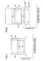
- Fig. 7 illustrates the relation between the pressing force and the location of the nip in the longitudinal direction of the nip.
- the pressing force in Fig. 7 is exerted on the entire width of the nip N.
- the recording medium 30 is thicker at the bonded portions 30a than at an area surrounded by the bonded portions 30a.
- the cam surface 13a is further away from its rotational axis at an area between the bonded portions 30a than at the bonded portions 30a. That is, the width W' is smaller than the width W of the recording medium 30. Therefore, when the cam 13 is at the rotational position shown in Figs.
- the middle portion W' of the cam surface 13b applies a larger pressing force to the pressure pad 14 than the rest of the cam surface 13b.
- This configuration provides a uniform pressing force across the length of the cam 13 in Fig. 6, ensuring a good fixing operation across the entire width of the recording medium 30.
- This angular position of the cam 13 at which best printing can be performed for envelopes is referred to as "ENVELOPE position" in this specification.
- pressing forces can be distributed appropriately across the pressure pad 14 so that the uniform nip N can be formed to improve print quality.
- Fig. 8 is a graph of the prior art, illustrating the pressing force versus the location of nip in the longitudinal direction of heating roller 11.
- the pressing force in Fig. 4 is exerted on the entire width of the nip N.
- the recording medium 29 such as cut-sheets
- a uniform pressing force can be applied across the width W of the recording medium 29 as shown in Fig. 8.
- the nip N is formed in accordance with the thickness of the bonded portions 30a of the recording medium 30.
- the pressing force is larger at the bonded portions 30a than at an area bounded between the bonded portions 30a. This is detrimental to good fixing results.
- the configuration of the present embodiment eliminates the need for the heat roller 11 having a large diameter and the coating 11c having a large thickness, so that the printer need not be large in overall size and the heat roller 11 need not be large in heat capacity. This leads to saving of electric power.
- cam surfaces 13a and 13b need not be diametrically opposite but may be angularly spaced by, for example, 90 degrees.
- the cam 13 is positioned selectively at the ORDINARY PAPER position and the ENVELOPE position in the first embodiment, the cam 13 is not limited to this configuration.
- the cam 13 may have additional rotational positions such as "release position” at which no pressing force is applied to the heat roller 11, "THICK PAPER position” at which fixing is performed on a recording medium having a large thickness, and "THIN PAPER position” at fixing is performed on a recording medium having a small thickness.
- the recording medium 30 has been described with respect to an envelope having non-uniform thickness across its width, the recording medium 30 may take other forms such as label paper and transparency.
- the above-described configuration provides a uniform distribution of pressing force for a recording medium having a surface that is partially coated and therefore has a non-uniform thickness across its surface.
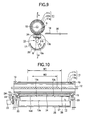
- Fig. 9 is a cross sectional view of a fixing unit according to a second embodiment.
- Fig. 10 is a cross-sectional view taken along line Z-Z of Fig. 9.
- a pad plate 38 is disposed on the opposite side of a pressure pad 34 from an arcuate recess.
- the pad plate 38 extends in a longitudinal direction and is made of a thin plate of SUS, which is resiliently deformable in a direction parallel to the longitudinal axis of the pressure pad 14.
- Supporting members 15 on a body of printer firmly supports the pressure pad 34 and pad plate 38 in place.
- a cam 13 is rotatably supported on bearings 20 under the pressure pad 34.
- the cam 13 has a circumferential cam surface 13a having a predetermined radius with respect to a rotational axis of the cam 13.
- the cam 13 also has a surface 13d on the diametrically opposite side of the cam 13 from the cam surface 13a.
- the cam surface 13d has short projections 13c that radially outwardly project from the cam surface 13d and extend in a circumferential direction.
- the projections 13c are located within the width W' and a predetermined distance away from the surface 13d.
- the projections 13c serve to adjust the profile of distribution of the pressing force that acts on the pressure pad 34.
- the controller 26 When fixing is performed on the recording medium 29, i.e. , a cut-sheet having a uniform thickness, the controller 26 provides a predetermined number of pulses to the pulse motor 22, thereby positioning the cam 13 at the ORDINARY PAPER position. In other words, the cam surface 13a is brought into contact with the pressure pad 34.
- the controller 26 When fixing is performed on the recording medium 30, i.e. , an envelope having a non-uniform thickness in the width direction, the controller 26 provides a predetermined number of pulses to the pulse motor 22, thereby positioning the cam 13 at the ENVELOPE position in Fig. 9 and Fig. 10.
- the proj ections 13c push the pad plate 38, causing the pad plate 38 and pressure pad 34 to deform so that the pad plate 38 and pressure pad 34 have an arcuate surface.
- the pad plate 38 and pressure pad 34 are deformed such that the arcuate surface is further away from the cam surface 13d nearer the longitudinal center of the cam 13.
- deformation of the pad plate 38 and pressure pad 34 presses a fixing belt 28 against the heat roller 11.
- the above-described configuration allows the pressing force to be larger at an area between the bonded portions 30a than at the bonded portions 30a.
- the pressing force is distributed more uniformly across the width of the recording medium when the projections 13c are employed than when the projections 13c are not employed, so that fixing is performed reliably across the width W of the recording medium 30.
- the pad plate 38 is arranged between the pressure pad 34 and the cam 13 to adjust an amount of deformation of the pressure pad 34. Therefore, a desired nip region N can be obtained without having to use the cam 13 with a complicated shape. This reduces the manufacturing cost of the fixing unit.
- each of the projections 13c can be small, a plurality of projections 13c may be provided on the cam surface 13d of the cam 13.
- the pressing force can be distributed properly in accordance with the types of recording medium.
- Fig. 11 illustrates the relation between the pressing force and between the location of the nip in the longitudinal direction of the nip.
- the use of the resiliency of the pad plate 38 provides the smoothly varying distribution of the pressing force, so that fixing can be efficiently performed on the ordinary paper having a uniform thickness across its width as shown in Fig. 11.
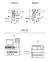
- Fig. 16 illustrates a printer system according to the third embodiment.
- a host apparatus 51 sends image data together with information on the recording medium.
- the information includes thickness, shape, and material to a printer 52.
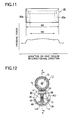
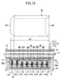
- Fig. 12 is a cross-sectional view of a fixing unit according to a third embodiment.
- Fig. 13 is a cross-sectional view taken along line A-A of Fig. 12.
- a pad plate 38 is disposed on the underside of the pressure pad 34 (i.e., on the opposite side of the pressure pad 34 from an arcuate recess that faces the heat roller 11) .
- the sub-mechanisms M1-M8 are identical. For simplicity, only the operation of the pressing mechanism M1 will be described, it being understood that the other sub-mechanisms M2-M8 work in a similar fashion.
- the pressing mechanism M1 includes a compression spring 40, a pressing pin 41 attached to an upper end of the compression spring 40, and a spring post 42 that is fixed to the supporting member 43 and supports the lower end portion of the compression spring 40.
- the link mechanism L1 includes a link Lb that pivots about a pin 44.
- the link Lb has one end coupled to a movable portion of the electromagnetic actuator AC1 and another end to a link Lc, which in turn is pivotally connected to a link La.
- the links Lc and La extend through opening 46.
- the actuator AC and the pins 44 and 45 are mounted on the supporting member 43.
- Figs. 14 and 15 illustrate the operation of a pressing mechanism N1 according to the third embodiment.
- the link La1 When the electromagnetic actuator AC1 is not energized, the link La1 is away from the lower end of the spring post 42 as shown in Fig. 14, so that the pressing pin 41 is at its lower position not to push up the spring post 42. Thus, the pressing pin 41 does not apply a pressing force to the pad plate 38.
- the electromagnetic actuator AC1 When the electromagnetic actuator AC1 is energized, the movable portion is retracted into the electromagnetic actuator AC as shown in Fig. 15, so that the link La rotates in a direction shown by arrow D to its higher position to push up the spring post 42. Thus, the pressing pin 41 is at its upper position to apply a pressing force to the pad plate 38.
- the eight sub-mechanisms M1-M8 are employed. Instead, a large number of sub-mechanisms having a miniaturized electromagnetic actuator and a link may be employed or a smaller number of sub-mechanisms having a simplified configuration may be employed depending on the type and shape of the recording medium.
- each sub-mechanism Mi is operated with corresponding electromagnetic actuator ACi and link Li
- the sub-mechanism Mi may be operated with any mechanism provided that the sub-mechanisms can be operated independently.
- the operation of the controller 26 will be described.
- the controller 26 reads the information on the recording medium received in a printer 52. Then, the controller 26 determines the type of recording medium and selects the position of the cam, i.e., an appropriate sub-mechanism in accordance with the type of recording medium. Then, a set of fixing temperature, printing speed, and pressing force is determined for the selected position.
- the ENVELOPE position is selected. If the recording medium has a uniform but larger thickness than the envelope, the THICK PAPER position is selected. If the recording medium has a smaller thickness than the ordinary paper, the THIN PAPER position is selected. If the recording medium has a standard thickness, then the ORDINARY PAPER position is selected. Likewise, if the recording medium is transparency, a predetermined position may be selected in accordance with a predetermined profile of distribution of pressing force.
- the controller 26 turns off the electromagnetic actuators AC3-AC8 upon selection of the ENVELOPE position and turns on the electromagnetic actuators AC1 and AC2. If the THICK PAPER position is selected, the controller 26 turns off the electromagnetic actuators AC1-AC8. If the THIN PAPER position is selected, the controller 26 turns on the electromagnetic actuators AC1-AC8. If the ORDINARY PAPER position is selected, the controller 26 turns off the electromagnetic actuators AC1, AC3-AC6, AC8 and turns on the electromagnetic actuators AC2 and AC7.
- the recording medium 30 When a large size envelope as shown in Fig. 13 is used, the recording medium 30 has a bonded portion 30a at one widthwise end and at one longitudinal end of the envelope, and a flap 30d at another longitudinal end of the envelope. Thus, the recording medium 30 has a large thickness at the bonded portion 30a and a small thickness at the flap 30d.
- the sub-mechanisms M1 and M2, which correspond to the smaller thickness of the recording medium 30, are operated to press the pad plate 38 and pressure pad 34 as shown in Fig. 13, thereby adjusting the distribution of pressing force in accordance with the recording medium 30 for reliable fixing performance across the entire surface of the recording medium 30.
- the recording medium 30 is an envelope having bonded portions 30a such as ones in the first and second embodiments or an envelope having different sizes from those in the first and second embodiments
- a plurality of ENVELOPE positions may be provided. Then, an appropriate one of the plurality of ENVELOPE positions may be selected according to the size of a specific envelope. Thus, an appropriate profile of the pressing force can be obtained across the length of the nip N.
- the distribution of the pressing force can be adjusted without replacing the sub-mechanism, thereby reducing the cost of the fixing unit.
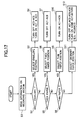
- Fig. 17 is a flowchart illustrating the operation of the fixing unit according to the third embodiment.
- Step S1 The controller 26 reads the information on the recording medium accommodated in a printer 52.
- Step S2 The controller 26 determines the type of the recording medium. If the recording medium is an envelope, the program proceeds to step S3. If NO, then the program proceeds to step S5.
- Step S3 The controller 26 selects the ENVELOPE position.
- Step S4 The controller turns off the electromagnetic actuators AC3-AC8 and turns on the electromagnetic actuators AC1 and AC2.
- Step S5 A decision is made to determine whether the recording medium is thick paper. If YES, then the program proceeds to step S6 where the controller 26 selects the THICK PAPER position. If NO, the program proceeds to step S8.
- Step S7 The controller 26 turns off the electromagnetic actuators AC1-AC8 off.
- Step S8 A decision is made to determine whether the recording medium is thin paper. If YES, the program proceeds to step S9. If NO, the program proceeds to step S11.
- Step S9 The controller 26 selects the THIN PAPER position.
- Step S10 The controller 26 turns on the electromagnetic actuators AC1-AC8.
- Step S11 The controller 26 selects the ORDINARY PAPER position.
- Step S12 The controller turns off the electromagnetic actuators AC1, AC3-AC6, and AC8 and turns on the other few electromagnetic actuators, for example, A2 and A7.
- the electromagnetic actuators AC2 and AC7 are turned on.
- the present invention is not limited to this configuration, but may be configured such that the electromagnetic actuators AC are provided at several locations to set a smaller pressing force for thick paper but a larger pressing force for thin paper.
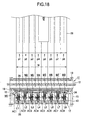
- Fig. 18 is a cross-sectional view of a fixing unit according to a fourth embodiment.
- Fig. 19 illustrates image data according to the fourth embodiment.
- the fourth embodiment employs eight sub-mechanisms M1-M8 that press eight different belt-shaped areas of the recording member, the eight different belt-shaped areas extending in parallel in the direction of travel of the recording medium. This configuration allows increasing of the pressing force for areas in which the image is printed at high print duty.
- the controller 26 Upon determining the type of print medium, the controller 26 reads image data and makes a decision to determine a print duty based on the size of the image area of the image data, the ratio of an actual image area of the recording medium to the total available image area on the recording medium. Thus, the controller 26 determines whether an image to be printed contains a high print duty.
- the sub-mechanism M5 that corresponds to the area P5 presses the pad plate 38 and pressure pad 34.
- the controller 26 turns on the electromagnetic actuator AC5 in addition to the electromagnetic actuators AC2 and AC7.
- the distribution of pressing force can be set based on not only the information on the recording medium but also print duty of the image data, so that the image quality is further improved.
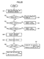
- Fig. 20 is a flowchart illustrating the operation of the fourth embodiment. The operation of the fourth embodiment will be described with reference to Fig. 20.
- Step S21 The controller 26 reads information on the recording medium.
- Step S22 The controller 26 makes a decision to determine whether the recording medium is an envelope. If YES, then the program proceeds to step S23. If NO, the program proceeds to Step S24.
- Step S23 The controller 26 selects the ENVELOPE position.
- Step S24 The controller 26 makes a decision to determine whether the recording medium is thick paper. If YES, then the program proceeds to Step S25. If NO, the program proceeds to step S26.
- Step S25 The controller 26 selects the THICK PAPER position.
- Step S26 The controller 26 makes a decision to determine whether the recording medium is thin paper. If YES, the program proceeds to step S27 . If NO, then the program proceeds to step S28 .
- Step S27 The controller 26 selects the THIN PAPER position.
- Step S28 The controller 26 selects the ORDINARY PAPER position.
- Step S29 The controller 26 reads image data.
- Step S30 The controller 26 makes a decision to determine whether the high print duty has been specified. If YES, the program proceeds to step S31. If NO, the program proceeds to step S32.
- Step S31 The controller 26 turns off the electromagnetic actuators AC1, AC3, AC4, AC6 and AC8 and turns on the electromagnetic actuators AC2, AC5 and AC7.
- the distribution of pressing force is set based on the information on the recording medium and image data.
- the conditions of the environment in which the printer and the recording medium are placed i. e. , temperature and humidity may also be used to implement a desired profile of distribution of pressing force. If such environmental conditions are used, creases in the recording medium may be removed by applying the pressing force to crinkled areas of the recording medium, even if the recording member is apt to become crinkled.
- the present invention has been described with respect to the heat roller 11 of the soft roller type, the present invention may also be applicable to a hard roller type heat roller and a belt fixing type heat roller.
- Fig. 21A-21C illustrate modification of the cam 13.
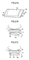
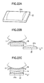
- Figs. 22A-22C illustrate a modification of the cam.
- the first and second embodiments are configured such that the cam 13 rotates to set a desired profile of the distribution of pressing force.
- the profile of distribution of pressing force may be set by moving a flat plate-like pressure member 31 in directions shown by arrows G and H along the transport path of the recording medium, the pressure member having a projection 31b in a predetermined shape on a plate like member that opposes the pressure pads 14 and 34 as shown in Fig. 22A-22C.
- the distribution of pressing force may be set by causing a pressure member 16 to pivot about pins 16c in directions shown by arrows E and F, the pressure member having a predetermined projection on a surface that faces the pressure pads 14 and 34 as shown in Fig. 21A-21C.
Landscapes
- Physics & Mathematics (AREA)
- General Physics & Mathematics (AREA)
- Fixing For Electrophotography (AREA)
Abstract
Description
- The present invention relates to a fixing apparatus and an image-forming apparatus.
- Among image-forming apparatus are a printer, a copying machine, and a facsimile machine that use an electrophotographic image-forming process. Such an image-forming apparatus is equipped with a fixing unit in which a toner image deposited on a recording medium is fused into a permanent image. The fixing unit includes a heat roller having a built-in heater therein, a pressure pad that opposes the heat roller, and a fixing belt that is sandwiched between the heat roller and the pressure pad and pressed against the heat roller by the pressure pad.
- The pressure pad presses the fixing belt against the heat roller to create a nip between the fixing belt and the heat roller. However, the aforementioned conventional fixing unit suffers from the problem that the nip region is difficult to be uniform for different types of recording medium and non-uniform nips cause poor print quality.
- The present invention was made in view of the aforementioned problems.
- An object of the invention is to provide a fixing apparatus and an image-forming apparatus where a uniform nip can be formed to improve image quality.
- A fixing apparatus operates to fix a toner image on a recording medium. A heating member (11) extends in a first direction transverse to a second direction in which a recording medium travels for fixing. A belt (28) contacts the heater member (11) to form a fixing region (N) between the belt and the heating member (11). A pressure member (14, 34) presses the belt (28) against the heating member (11) . A pressing mechanism (13, M1-M8) engages the pressure member (11) to apply a predetermined pressure to the pressure member (11) toward the fixing region (N) in such a way that the pressure has an adjustable profile of distribution in the first direction.
- The pressing mechanism (13, M1-M8) is a rotatable member (13) that extends in a third direction substantially parallel to the first direction. The rotatable member (13) has a surface (13a, 13b, 13c, 13d) that is brought into contact engagement with the pressure member (14, 34) when the rotatable member (13) is rotated, the surface has a predetermined profile of geometry in the third direction such that the pressing force has the predetermined profile of distribution in the first direction.
- The fixing apparatus may further include a deformable resilient member (38) disposed between the pressing mechanism (M1-M8) and the pressure member (14, 34) , the deformable resilient member (38) extending in a direction generally parallel to the first direction.
- The pressing mechanism (M1-M8) includes a plurality of sub-mechanisms (M1-M8) aligned in a direction generally parallel to the first direction. The plurality of sub-mechanisms (M1-M8) are adjustable independently so that each of the plurality of sub-mechanisms applies different amounts of force to the pressure member.
- An image-forming apparatus has a fixing apparatus. The fixing apparatus includes:
- a heating member (11) that extends in a first direction transverse to a second direction in which a recording medium is advanced;
- a belt (28) that is in contact with the heater member (11) to form a fixing region (N) between the belt and the heating member (11) so that the recording medium passes through the fixing region (N) for fixing;
- a pressure member (14, 34) that presses the belt (28) against the heating member (11);
- a pressing mechanism (13, M1-M8) that engages the pressure member to apply a pressing force to the pressure member toward the fixing region (N); and
- a controller (26) that drives the pressing mechanism (13, M1-M8) to adjust the pressing force in such a way that the pressing force has an adjustable profile of distribution in the first direction.
-
- The pressing mechanism (13) of the image-forming apparatus is rotatable and extends in a third direction substantially parallel to the first direction, wherein the pressing mechanism (13) has a surface (13a, 13b, 13c, 13d) that is brought into contact engagement with the pressure member (14, 34) to apply a pressing force to the pressure member toward the fixing when the rotatable member is rotated, the surface having a predetermined profile of geometry in the third direction such that the pressing force has the predetermined profile of distribution in the first direction.
- The fixing apparatus of the image-forming apparatus further includes a deformable resilient member (38) disposed between the pressing mechanism (M1-M8) and the pressure member (14, 34), the deformable resilient member (38) extending in a direction generally parallel to the first direction.
- The pressing mechanism (M1-M8) of the image-forming apparatus includes a plurality of sub-mechanisms (M1-M8) aligned in a direction generally parallel to the first direction. The plurality of sub-mechanisms (M1-M8) are adjustable independently so that each of the plurality of sub-mechanisms applies different amounts of force to the pressure member.
- The controller (26) drives the plurality of sub-mechanisms (M1-M8) in accordance with information on the recording medium.
- The controller (26) drives the plurality of sub-mechanisms (M1-M8) in accordance with at least one of environmental temperature and humidity.
- The controller (26) determines a print duty based on image data that should be printed on the recording medium, the controller (26) adjusting the profile of distribution in accordance with the print duty.
- A fixing apparatus includes:
- a heating member (11) that extends in a first direction transverse to a second direction in which a recording medium is advanced;
- a belt (28) that is in contact with the heater member (11) to form a fixing region (N) between the belt and the heating member (11) so that the recording medium passes through the fixing region (N) for fixing;
- a pressure member (14, 34) that presses the belt (28) against the heating member (11);
- a pressing mechanism (13, M1-M8) that engages the pressure member to apply a predetermined pressing force to the pressure member toward the fixing region (N) in such a way that the pressing force has a predetermined profile of distribution in the first direction.
-
- An image-forming apparatus incorporates the aforementioned fixing apparatus. The image-forming apparatus includes a controller (26) that drives the pressing mechanism (13, M1-M8) to adjust the pressing force in such a way that the pressing force has a predetermined profile of distribution in the third direction.
- Further scope of applicability of the present invention will become apparent from the detailed description given hereinafter. However, it should be understood that the detailed description and specific examples, while indicating preferred embodiments of the invention, are given by way of illustration only, since various changes and modifications within the spirit and scope of the invention will become apparent to those skilled in the art from this detailed description.
- The present invention will become more fully understood from the detailed description given hereinbelow and the accompanying drawings which are given by way of illustration only, and thus are not limiting the present invention, and wherein:
- Fig. 1A is a cross-sectional view of a fixing unit according to a first embodiment;
- Fig. 1B illustrates a partial expanded view of Fig. 1A;
- Fig. 2 is a cross-sectional view taken along line X-X of Fig. 1A;
- Fig. 3 is a schematic perspective view illustrating a nip-adjusting unit according to the first embodiment;
- Fig. 4 illustrates the relation between the axial length of a heat roller and the pressure exerted on the heat roller;
- Fig. 5 is a cross-sectional view of the fixing unit according to the first embodiment;
- Fig. 6 is a cross-sectional view taken along line Y-Y of Fig. 5;
- Fig. 7 illustrates the relation between the pressing force and the location of the nip in the longitudinal direction of the nip;
- Fig. 8 is a graph of the prior art, illustrating the pressing force versus the location of nip in the longitudinal direction of heating roller;
- Fig. 9 is a cross sectional view of a fixing unit according to a second embodiment;
- Fig. 10 is a cross-sectional view taken along line Z-Z of Fig. 9;
- Fig. 11 illustrates the relation between the pressing force and between the location of the nip in the longitudinal direction of the nip;
- Fig. 12 is a cross-sectional view of a fixing unit according to a third embodiment;
- Fig. 13 is a cross-sectional view taken along line A-A of Fig. 12;
- Figs. 14 and 15 illustrate the operation of a pressing mechanism N1 according to the third embodiment;
- Fig. 16 illustrates a printer system according to the third embodiment;
- Fig. 17 is a flowchart illustrating the operation of the fixing unit according to the third embodiment;
- Fig. 18 is a cross-sectional view of a fixing unit according to a fourth embodiment;
- Fig. 19 illustrates image data according to the fourth embodiment;
- Fig. 20 is a flowchart illustrating the operation of the fourth embodiment;
- Figs. 21A-21C illustrate a modification of the cam; and
- Figs. 22A-22C illustrate a modification of the cam.
-
- The present invention will be described with reference to the accompanying drawings. A printer will be described as an example of an image forming apparatus.
- Fig. 1A is a cross-sectional view of a fixing unit according to a first embodiment.
- Fig. 1B illustrates a partial expanded view of Fig. 1A.
- Fig. 2 is a cross-sectional view taken along line X-X of Fig. 1A.
- Referring to Fig. 1A, a
heat roller 11 includes acore metal 11a with aresilient layer 11b formed on it and acoating layer 11c formed on theresilient layer 11b. Theheat roller 11 incorporates aheater 12 as a built-in heater and is supported at opposite longitudinal end portions bybearings 19. A controller 26 (Fig. 3) performs a heating operation in which theheater 12 is energized to heat theheat roller 11 to a predetermined temperature. Then, thecontroller 26 drives a motor 22 (Fig. 3) that drives the fixing unit, thereby causing theheat roller 11 to rotate at a predetermined speed. A thermistor, not shown, is in contact with the outer circumferential surface of theheat roller 11 to detect the temperature of the circumferential surface. - Fig. 1B is an enlarged view of a pertinent portion of Fig. 1A.
- A
cam 13 is disposed under apressure pad 14 and rotatably supported onbearings 20. Thecam 13 is rotatable about an axis Q in directions shown by arrows B and C. Thecam 13 has acam surface 13a that applies pressure against thepressure pad 14 when the cam surface engages thepressure pad 14 as shown in Fig. 1A. The cam surface has a radius of curvature r, as shown in Fig. 1B. Thecam 13 also has anothercam surface 13b that applies pressure against thepressure pad 14 when thecam surface 13b engages thepressure pad 14 as shown in Fig. 5. Thecam surface 13b are at diametrically opposite side of thecam 13 from thecam surface 13a. The cam surfaces 13a and 13b extend in their longitudinal direction and in their circumferential direction. Thecam 13 is designed to have distances a, b, and c such that a<b<c. - The
cam 13 has one end to which a circular light-blockingdisk 23 is attached. The circular light-blocking disk has aslit 23a (Fig. 3) formed in its circumferential peripheral portion. The light-blockingdisk 23 is disposed in such a way that when thelight blocking disk 23 rotates, theslit 23a rotates into and out of a light path of aposition detector 24. - The
cam 13 has agear 21a mounted near the light-blockingplate 23 that is in mesh with agear 21b. Thegear 21b is mounted on a shaft of apulse motor 22. The rotation of thepulse motor 22 is transmitted to thecam 13 via a gear train formed of thegears - The
pressure pad 14 is made of a resilient, heat-resistive material. Thepressure pad 14 opposes theheat roller 11 and extends in a direction parallel to the longitudinal axis of theheat roller 11. When no pressure is exerted on thepressure pad 14, thepressure pad 14 has a rectangular cross-section. When thecam 13 rotates to a position shown in Fig. 1A, the cam surface applies a predetermined pressing force to thepressure pad 14 and thepressure pad 14 is resiliently deformed accordingly as shown in Fig. 1A, thereby transmitting the pressing force to theheat roller 11. Supportingmembers 15 on a body of the printer firmly support thepressure pad 14 at longitudinal ends of thepressure pad 14. - A
belt guide 17 has an arcuate cross section and is disposed under thepressure pad 14. A fixingbelt 28 is an endless belt and forms a nip N (i.e., fixing region) between the fixingbelt 28 and theheat roller 11. The fixingbelt 28 runs in a loop-like path, which surrounds thepressure pad 14, canshaft 13, andbelt guide 17 and passes between theheat roller 11 and thepressure pad 14. Thus, thepressure pad 14 presses theheat roller 11 with the fixingbelt 28 sandwiched therebetween. Thepressure pad 14,cam 13,belt guide 17 and fixingbelt 28 form a fixing unit. - The
pressure pad 14 receives a pressing force from thecam 13 to press the fixingbelt 28 against theheat roller 11, thereby creating a nip N between theheat roller 11 and the fixingbelt 28. The nip forms a fixing region through which a recording medium passes for fixing. - When the
heat roller 11 rotates in a direction shown by arrow A, the friction between theheat roller 11 and fixingbelt 28 causes the fixingbelt 28 to run in the loop-like path, so that therecording medium 29 such as paper and transparency is transported through the nip N. - The
pressure pad 14 is deformed by a pressing force such that the nip N is an arcuate recess formed therein that faces theheat roller 11. Alternatively, thepressure pad 14 may have a pre-shaped arcuate recess configured to the outer circumferential surface of theheat roller 11. The pre-shaped arcuate recess provides a reliable shape of the nip N. - The operation of the aforementioned configuration of the fixing unit will be described. It is assumed that color printing is performed on a recording medium in the form of a cut-sheet having a width W and a uniform thickness.
- When a host computer, not shown, such as a personal computer issues a print command to the printer, a paper-feeding section, not shown, feeds the
recording medium 29 from a paper cassette. Therecording medium 29 is then advanced by feeding rollers, not shown, through yellow, magenta, cyan, and black image-forming sections, not shown, in sequence. - Each image-forming section receives image data of a corresponding color from the host apparatus and forms a toner image of the corresponding color. As the
recording medium 29 advances through the respective image-forming sections, the toner images of corresponding colors are transferred onto therecording medium 29 one over the other in sequence, creating a full-color toner image. - The following operations are performed at the same time as the image-forming processes at the respective image-forming sections.
- The
cam 13 is positioned so that thecam surface pressure pad 14. A minimum sufficient pressing force is applied to thepressure pad 14, thereby preventing permanent deformation and deterioration of theheat roller 11 andpressure pad 14 due to the heat received from theheater 12 and the pressure applied through thepressure pad 14. - Fig. 3 is a schematic perspective view illustrating a nip-adjusting unit according to the first embodiment.
- A
setting section 27 stores the number of pulses that are used to drive thepulse motor 22 to rotate. Thecontroller 26 drives thepulse motor 22 in rotation so that when theslit 23a enters the light path of theposition detector 24, theposition detector 24 generates a sensor output. The sensor output is sent to adetector 25. Thedetector 25 provides a detection signal to thecontroller 26, the detection signal indicating that thecam 13 is at a predetermined reference position (Fig. 3) . Upon the detection of theslit 23a, thecontroller 26 causes thepulse motor 22 to stop at the predetermined reference position where thecam 13 exerts the smallest pressure on thepressure pad 14. - Then, the
controller 26 performs a pressure distribution adjusting operation. In other words, thecontroller 26 supplies a predetermined number of pulses to thepulse motor 22 and thepulse motor 22 drives thecam 13 to rotate through an angle corresponding to the number of pulses specified from thesetting section 27. Thus, a predetermined profile of distribution of pressing force can be set across the length of theheat roller 11 by means of the cam surfaces 13a and 13b. Upon receiving the print command from the host apparatus, theheater 12 begins to heat theheat roller 11. - When the printer receives information on the
recording medium 29 such as size, thickness, shape, and material, thecontroller 26 provides a predetermined number of pulses to thepulse motor 22. In accordance with the predetermined number of pulses, the pulse motor rotates thecam 13 from the reference rotational position to a rotational position shown in Figs. 1 and 2. Thus, thecam surface 13a of thecam 13 applies a pressing force to thepressure pad 14, thereby transmitting a pressing force to theheat roller 11 with a desired profile of distribution across the length of thecam 13. When printing is performed on ordinary paper, the position of thecam 13 is at the angular position in Figs. 1 and 2. This angular position of thecam 13 is referred to as "ORDINARY PAPER position" in the present embodiment. - When the surface temperature of the
heat roller 11 detected by the thermistor reaches a predetermined value, thecontroller 26 drives the motor to rotate theheat roller 11 at a predetermined rotational speed, so that the fixingbelt 28 runs to maintain the entire surfaces of theheat roller 11 and fixingbelt 28 at a uniform temperature. - The
cam 13 is rotated before theheat roller 11 begins to rotate so that the nip is created concurrently with the image-forming processes of the respective image-forming sections. This operation not only shortens the time required for printing but also transmits a pressing force to theheat roller 11, the pressing force having the same profile of distribution as in an actual fixing operation. This operation allows preheating of theheat roller 11 and fixingbelt 28 to a stable, high temperature at the nip N. Thecam 13 can be rotated to create an appropriate nip N at any timing before therecording medium 29 reaches the nip N. - When the
recording medium 29 having atoner image 18 thereon enters the nip N, thetoner image 18 is heated at a predetermined temperature so that thetoner image 18 is fused into therecording medium 29 under an appropriate pressure. - Fig. 4 illustrates the relation between the axial length of a heat roller and the pressure exerted on the heat roller.
- If the
recording medium 29 is ordinary paper, the pressing force exerted on theheat roller 11 is substantially uniform across the entire length of theheat roller 11 as shown in Fig. 4. This ensures reliable fixing results. The pressing force in Fig. 4 is exerted on the entire width of the nip N. - The operation will be described when a recording medium is, for example, an envelope bonded at the same locations and having the same width W but different thicknesses at different locations. Such a recording medium can be fixed reliably. Elements having similar configurations as those in Figs. 1 and 2 have been given the same reference numerals, and the description thereof is omitted.
- Fig. 5 is a cross-sectional view of the fixing unit according to the first embodiment.
- Fig. 6 is a cross-sectional view taken along line Y-Y of Fig. 5.
- Upon a print command from the host apparatus, the
heater 12 begins to heat theheat roller 11. If arecording medium 30 is an envelope, therecording medium 30 differs from therecording medium 29 in thickness and crease-resistance. Thus, experiment was conducted for different types of recording medium to investigate the relation between the types of recording medium and corresponding fixing temperatures required. The relation is listed in Table 1.TYPE OF MEDIUM TEMPERATURE (°C) DISTRIBUTION OF PRESSING FORCE ACROSS HEAT ROLLER THIN PAPER 164 UNIFORM THICK PAPER 170 UNIFORM SLIGHTLY THICK PAPER 182 UNIFORM THICK PAPER 185 UNIFORM ENVELOPE # 1 164 HIGH IN THE MIDDLE ENVELOPE #2 174 HIGH IN THE MIDDLE OHP # 1 162 UNIFORM OHP #2 164 UNIFORM - When the printer receives information on a recording medium such as size, thickness, shape, and material, the controller provides a predetermined number of pulses to the
pulse motor 22. Then, in accordance with the predetermined number of pulses, the pulse motor rotates thecam 13 from the reference rotational position to a rotational position shown in Figs. 5 and 6. - Fig. 7 illustrates the relation between the pressing force and the location of the nip in the longitudinal direction of the nip. The pressing force in Fig. 7 is exerted on the entire width of the nip N. Because the envelope has folded and bonded
portions 30a, therecording medium 30 is thicker at the bondedportions 30a than at an area surrounded by the bondedportions 30a. For this reason, thecam surface 13a is further away from its rotational axis at an area between the bondedportions 30a than at the bondedportions 30a. That is, the width W' is smaller than the width W of therecording medium 30. Therefore, when thecam 13 is at the rotational position shown in Figs. 5 and 6, the middle portion W' of thecam surface 13b applies a larger pressing force to thepressure pad 14 than the rest of thecam surface 13b. This configuration provides a uniform pressing force across the length of thecam 13 in Fig. 6, ensuring a good fixing operation across the entire width of therecording medium 30. This angular position of thecam 13 at which best printing can be performed for envelopes is referred to as "ENVELOPE position" in this specification. - As described above, when different types of recording media are to be printed, pressing forces can be distributed appropriately across the
pressure pad 14 so that the uniform nip N can be formed to improve print quality. - It is only necessary to rotate the
cam 13 for setting the profile of distribution of pressing force in the longitudinal direction of the nip N. For achieving a desired profile of pressure distribution across the length ofheating roller 11, there is no need for selecting different combinations of, for example, pressurizing springs or precisely adjusting relative positions between the fixing unit and the body of the printer. Thus, the configuration prevents variations of pressing force across the length of theheat roller 11. - Fig. 8 is a graph of the prior art, illustrating the pressing force versus the location of nip in the longitudinal direction of
heating roller 11. The pressing force in Fig. 4 is exerted on the entire width of the nip N. - In the conventional fixing apparatus, when the
recording medium 29 such as cut-sheets is used, a uniform pressing force can be applied across the width W of therecording medium 29 as shown in Fig. 8. However, if fixing is to be performed on an envelope, the nip N is formed in accordance with the thickness of the bondedportions 30a of therecording medium 30. As a result, the pressing force is larger at the bondedportions 30a than at an area bounded between the bondedportions 30a. This is detrimental to good fixing results. - The configuration of the present embodiment eliminates the need for the
heat roller 11 having a large diameter and thecoating 11c having a large thickness, so that the printer need not be large in overall size and theheat roller 11 need not be large in heat capacity. This leads to saving of electric power. - The cam surfaces 13a and 13b need not be diametrically opposite but may be angularly spaced by, for example, 90 degrees.
- While the
cam 13 is positioned selectively at the ORDINARY PAPER position and the ENVELOPE position in the first embodiment, thecam 13 is not limited to this configuration. Thecam 13 may have additional rotational positions such as "release position" at which no pressing force is applied to theheat roller 11, "THICK PAPER position" at which fixing is performed on a recording medium having a large thickness, and "THIN PAPER position" at fixing is performed on a recording medium having a small thickness. - While the
recording medium 30 has been described with respect to an envelope having non-uniform thickness across its width, therecording medium 30 may take other forms such as label paper and transparency. - The above-described configuration provides a uniform distribution of pressing force for a recording medium having a surface that is partially coated and therefore has a non-uniform thickness across its surface.
- Elements similar to those in the first embodiment have been given the same reference numerals and the description thereof is omitted.
- Fig. 9 is a cross sectional view of a fixing unit according to a second embodiment.
- Fig. 10 is a cross-sectional view taken along line Z-Z of Fig. 9.
- A
pad plate 38 is disposed on the opposite side of apressure pad 34 from an arcuate recess. Thepad plate 38 extends in a longitudinal direction and is made of a thin plate of SUS, which is resiliently deformable in a direction parallel to the longitudinal axis of thepressure pad 14. Supportingmembers 15 on a body of printer firmly supports thepressure pad 34 andpad plate 38 in place. - A
cam 13 is rotatably supported onbearings 20 under thepressure pad 34. Thecam 13 has acircumferential cam surface 13a having a predetermined radius with respect to a rotational axis of thecam 13. Thecam 13 also has asurface 13d on the diametrically opposite side of thecam 13 from thecam surface 13a. Thecam surface 13d hasshort projections 13c that radially outwardly project from thecam surface 13d and extend in a circumferential direction. Theprojections 13c are located within the width W' and a predetermined distance away from thesurface 13d. Theprojections 13c serve to adjust the profile of distribution of the pressing force that acts on thepressure pad 34. - When fixing is performed on the
recording medium 29, i.e. , a cut-sheet having a uniform thickness, thecontroller 26 provides a predetermined number of pulses to thepulse motor 22, thereby positioning thecam 13 at the ORDINARY PAPER position. In other words, thecam surface 13a is brought into contact with thepressure pad 34. - When fixing is performed on the
recording medium 30, i.e. , an envelope having a non-uniform thickness in the width direction, thecontroller 26 provides a predetermined number of pulses to thepulse motor 22, thereby positioning thecam 13 at the ENVELOPE position in Fig. 9 and Fig. 10. - The proj ections 13c push the
pad plate 38, causing thepad plate 38 andpressure pad 34 to deform so that thepad plate 38 andpressure pad 34 have an arcuate surface. Thepad plate 38 andpressure pad 34 are deformed such that the arcuate surface is further away from thecam surface 13d nearer the longitudinal center of thecam 13. Thus, deformation of thepad plate 38 andpressure pad 34 presses a fixingbelt 28 against theheat roller 11. - The above-described configuration allows the pressing force to be larger at an area between the bonded
portions 30a than at the bondedportions 30a. Thus, the pressing force is distributed more uniformly across the width of the recording medium when theprojections 13c are employed than when theprojections 13c are not employed, so that fixing is performed reliably across the width W of therecording medium 30. - In the present embodiment, the
pad plate 38 is arranged between thepressure pad 34 and thecam 13 to adjust an amount of deformation of thepressure pad 34. Therefore, a desired nip region N can be obtained without having to use thecam 13 with a complicated shape. This reduces the manufacturing cost of the fixing unit. - Because each of the
projections 13c can be small, a plurality ofprojections 13c may be provided on thecam surface 13d of thecam 13. Thus, the pressing force can be distributed properly in accordance with the types of recording medium. - Fig. 11 illustrates the relation between the pressing force and between the location of the nip in the longitudinal direction of the nip. The use of the resiliency of the
pad plate 38 provides the smoothly varying distribution of the pressing force, so that fixing can be efficiently performed on the ordinary paper having a uniform thickness across its width as shown in Fig. 11. - Elements similar to those in the second embodiment have been given the same reference numerals and the description thereof is omitted.
- Fig. 16 illustrates a printer system according to the third embodiment. Referring to Fig. 16, a
host apparatus 51 sends image data together with information on the recording medium. The information includes thickness, shape, and material to aprinter 52. - Fig. 12 is a cross-sectional view of a fixing unit according to a third embodiment.
- Fig. 13 is a cross-sectional view taken along line A-A of Fig. 12.
- A
pad plate 38 is disposed on the underside of the pressure pad 34 (i.e., on the opposite side of thepressure pad 34 from an arcuate recess that faces the heat roller 11) . There are provided a plurality of sub-mechanisms M1-M8 that are supported on a supportingmember 43 and aligned in a line under thepad plate 38. Each of the plurality of sub-mechanisms M1-M8 includes an electromagnetic actuator ACi (i=1, 2, 3,.... , 8) and a link mechanism Li (i=1, 2, 3, ...., 8) and operates independently of the other sub-mechanisms to press thepressure pad 34. - The sub-mechanisms M1-M8 are identical. For simplicity, only the operation of the pressing mechanism M1 will be described, it being understood that the other sub-mechanisms M2-M8 work in a similar fashion. The pressing mechanism M1 includes a
compression spring 40, apressing pin 41 attached to an upper end of thecompression spring 40, and aspring post 42 that is fixed to the supportingmember 43 and supports the lower end portion of thecompression spring 40. The link mechanism L1 includes a link Lb that pivots about apin 44. The link Lb has one end coupled to a movable portion of the electromagnetic actuator AC1 and another end to a link Lc, which in turn is pivotally connected to a link La. The links Lc and La extend throughopening 46. The actuator AC and thepins member 43. - Figs. 14 and 15 illustrate the operation of a pressing mechanism N1 according to the third embodiment.
- When the electromagnetic actuator AC1 is not energized, the link La1 is away from the lower end of the
spring post 42 as shown in Fig. 14, so that thepressing pin 41 is at its lower position not to push up thespring post 42. Thus, thepressing pin 41 does not apply a pressing force to thepad plate 38. When the electromagnetic actuator AC1 is energized, the movable portion is retracted into the electromagnetic actuator AC as shown in Fig. 15, so that the link La rotates in a direction shown by arrow D to its higher position to push up thespring post 42. Thus, thepressing pin 41 is at its upper position to apply a pressing force to thepad plate 38. - Thus, when the
controller 26 causes appropriate ones of the electromagnetic actuators Ac1-AC8 to operate, the corresponding links La pushes up thespring post 42, which in turn causes thepressing pin 41 to push up thepad plate 38. - In this manner, the pressing force is properly distributed across the entire width of the
recording medium 30. - In the third embodiment, the eight sub-mechanisms M1-M8 are employed. Instead, a large number of sub-mechanisms having a miniaturized electromagnetic actuator and a link may be employed or a smaller number of sub-mechanisms having a simplified configuration may be employed depending on the type and shape of the recording medium.
- While each sub-mechanism Mi is operated with corresponding electromagnetic actuator ACi and link Li, the sub-mechanism Mi may be operated with any mechanism provided that the sub-mechanisms can be operated independently.
- The operation of the
controller 26 will be described. Thecontroller 26 reads the information on the recording medium received in aprinter 52. Then, thecontroller 26 determines the type of recording medium and selects the position of the cam, i.e., an appropriate sub-mechanism in accordance with the type of recording medium. Then, a set of fixing temperature, printing speed, and pressing force is determined for the selected position. - If the recording medium is an envelope, the ENVELOPE position is selected. If the recording medium has a uniform but larger thickness than the envelope, the THICK PAPER position is selected. If the recording medium has a smaller thickness than the ordinary paper, the THIN PAPER position is selected. If the recording medium has a standard thickness, then the ORDINARY PAPER position is selected. Likewise, if the recording medium is transparency, a predetermined position may be selected in accordance with a predetermined profile of distribution of pressing force.
- If the recording medium is a large size envelope as shown in Fig. 13 and the ENVELOPE position is selected, the
controller 26 turns off the electromagnetic actuators AC3-AC8 upon selection of the ENVELOPE position and turns on the electromagnetic actuators AC1 and AC2. If the THICK PAPER position is selected, thecontroller 26 turns off the electromagnetic actuators AC1-AC8. If the THIN PAPER position is selected, thecontroller 26 turns on the electromagnetic actuators AC1-AC8. If the ORDINARY PAPER position is selected, thecontroller 26 turns off the electromagnetic actuators AC1, AC3-AC6, AC8 and turns on the electromagnetic actuators AC2 and AC7. - When a large size envelope as shown in Fig. 13 is used, the
recording medium 30 has a bondedportion 30a at one widthwise end and at one longitudinal end of the envelope, and aflap 30d at another longitudinal end of the envelope. Thus, therecording medium 30 has a large thickness at the bondedportion 30a and a small thickness at theflap 30d. Thus, the sub-mechanisms M1 and M2, which correspond to the smaller thickness of therecording medium 30, are operated to press thepad plate 38 andpressure pad 34 as shown in Fig. 13, thereby adjusting the distribution of pressing force in accordance with therecording medium 30 for reliable fixing performance across the entire surface of therecording medium 30. - If the
recording medium 30 is an envelope having bondedportions 30a such as ones in the first and second embodiments or an envelope having different sizes from those in the first and second embodiments, a plurality of ENVELOPE positions may be provided. Then, an appropriate one of the plurality of ENVELOPE positions may be selected according to the size of a specific envelope. Thus, an appropriate profile of the pressing force can be obtained across the length of the nip N. - As described above, operating arbitrary ones of the respective sub-mechanisms AC1-AC8 causes the
pad plate 38 andpressure pad 34 to deform into a desired shape to provide an optimum profile of distribution of pressing force. Thus, the distribution of the pressing force can be reliably set in accordance with various types of recording medium and the image quality can be improved. - In addition, the distribution of the pressing force can be adjusted without replacing the sub-mechanism, thereby reducing the cost of the fixing unit.
- Fig. 17 is a flowchart illustrating the operation of the fixing unit according to the third embodiment.
- The flowchart will be described.
- Step S1: The
controller 26 reads the information on the recording medium accommodated in aprinter 52. - Step S2: The
controller 26 determines the type of the recording medium. If the recording medium is an envelope, the program proceeds to step S3. If NO, then the program proceeds to step S5. - Step S3: The
controller 26 selects the ENVELOPE position. - Step S4: The controller turns off the electromagnetic actuators AC3-AC8 and turns on the electromagnetic actuators AC1 and AC2.
- Step S5: A decision is made to determine whether the recording medium is thick paper. If YES, then the program proceeds to step S6 where the
controller 26 selects the THICK PAPER position. If NO, the program proceeds to step S8. - Step S7: The
controller 26 turns off the electromagnetic actuators AC1-AC8 off. - Step S8: A decision is made to determine whether the recording medium is thin paper. If YES, the program proceeds to step S9. If NO, the program proceeds to step S11.
- Step S9: The
controller 26 selects the THIN PAPER position. - Step S10: The
controller 26 turns on the electromagnetic actuators AC1-AC8. - Step S11: The
controller 26 selects the ORDINARY PAPER position. - Step S12: The controller turns off the electromagnetic actuators AC1, AC3-AC6, and AC8 and turns on the other few electromagnetic actuators, for example, A2 and A7.
- In the present embodiment, when the ORDINARY PAPER position is selected, the electromagnetic actuators AC2 and AC7 are turned on. The present invention is not limited to this configuration, but may be configured such that the electromagnetic actuators AC are provided at several locations to set a smaller pressing force for thick paper but a larger pressing force for thin paper.
- Elements similar to those in the third embodiment have been given the same reference numerals and the description thereof is omitted.
- Fig. 18 is a cross-sectional view of a fixing unit according to a fourth embodiment.
- Fig. 19 illustrates image data according to the fourth embodiment.
- For graphic images, if the size of the image is large, or the print duty of the image is high due to the fact that image area represents a large percentage of the total area of the recording medium, particularly when a full color image is to be printed, a decrease in pressing force causes poor fixing such as "offset" that decreases image quality.
- In order to solve this problem, the fourth embodiment employs eight sub-mechanisms M1-M8 that press eight different belt-shaped areas of the recording member, the eight different belt-shaped areas extending in parallel in the direction of travel of the recording medium. This configuration allows increasing of the pressing force for areas in which the image is printed at high print duty.
- Upon determining the type of print medium, the
controller 26 reads image data and makes a decision to determine a print duty based on the size of the image area of the image data, the ratio of an actual image area of the recording medium to the total available image area on the recording medium. Thus, thecontroller 26 determines whether an image to be printed contains a high print duty. - For example, as shown in Figs. 18 and 19, if the
recording medium 29 has areas P1-P8 and an area P5 is to be printed at a high print duty, the sub-mechanism M5 that corresponds to the area P5 presses thepad plate 38 andpressure pad 34. - If, for example, the ORDINARY PAPER position has been selected, the
controller 26 turns on the electromagnetic actuator AC5 in addition to the electromagnetic actuators AC2 and AC7. - As described above, the distribution of pressing force can be set based on not only the information on the recording medium but also print duty of the image data, so that the image quality is further improved.
- Fig. 20 is a flowchart illustrating the operation of the fourth embodiment. The operation of the fourth embodiment will be described with reference to Fig. 20.
- Step S21: The
controller 26 reads information on the recording medium. - Step S22: The
controller 26 makes a decision to determine whether the recording medium is an envelope. If YES, then the program proceeds to step S23. If NO, the program proceeds to Step S24. - Step S23: The
controller 26 selects the ENVELOPE position. - Step S24: The
controller 26 makes a decision to determine whether the recording medium is thick paper. If YES, then the program proceeds to Step S25. If NO, the program proceeds to step S26. - Step S25: The
controller 26 selects the THICK PAPER position. - Step S26: The
controller 26 makes a decision to determine whether the recording medium is thin paper. If YES, the program proceeds to step S27 . If NO, then the program proceeds to step S28 . - Step S27: The
controller 26 selects the THIN PAPER position. - Step S28: The
controller 26 selects the ORDINARY PAPER position. - Step S29: The
controller 26 reads image data. - Step S30: The
controller 26 makes a decision to determine whether the high print duty has been specified. If YES, the program proceeds to step S31. If NO, the program proceeds to step S32. - Step S31: The
controller 26 turns off the electromagnetic actuators AC1, AC3, AC4, AC6 and AC8 and turns on the electromagnetic actuators AC2, AC5 and AC7. - In the fourth embodiment, the distribution of pressing force is set based on the information on the recording medium and image data. The conditions of the environment in which the printer and the recording medium are placed, i. e. , temperature and humidity may also be used to implement a desired profile of distribution of pressing force. If such environmental conditions are used, creases in the recording medium may be removed by applying the pressing force to crinkled areas of the recording medium, even if the recording member is apt to become crinkled.
- While the present invention has been described with respect to the
heat roller 11 of the soft roller type, the present invention may also be applicable to a hard roller type heat roller and a belt fixing type heat roller. - Fig. 21A-21C illustrate modification of the
cam 13. Figs. 22A-22C illustrate a modification of the cam. - The first and second embodiments are configured such that the
cam 13 rotates to set a desired profile of the distribution of pressing force. Alternatively, the profile of distribution of pressing force may be set by moving a flat plate-like pressure member 31 in directions shown by arrows G and H along the transport path of the recording medium, the pressure member having aprojection 31b in a predetermined shape on a plate like member that opposes thepressure pads pressure member 16 to pivot aboutpins 16c in directions shown by arrows E and F, the pressure member having a predetermined projection on a surface that faces thepressure pads - The invention being thus described, it will be obvious that the same may be varied in many ways. Such variations are not to be regarded as a departure from the spirit and scope of the invention, and all such modifications as would be obvious to one skilled in the art intended to be included within the scope of the following claims.
Claims (22)
- A fixing apparatus comprising:a heating member (11) that extends in a first direction transverse to a second direction in which a recording medium is advanced;a belt (28) that is in contact with said heater member (11) to form a fixing region (N) between said belt and said heating member (11) so that the recording medium passes through the fixing region (N) for fixing;a pressure member (14, 34) that presses said belt (28) against said heating member (11);a pressing mechanism (13, M1-M8) that engages said pressure member to apply a pressing force to said pressure member toward the fixing region (N) in such a way that the pressing force has an adjustable profile of distribution in the first direction.
- The fixing apparatus according to Claim 1, wherein said pressing mechanism (13, M1-M8) is a rotatable member (13) that extends in a third direction substantially parallel to the first direction;
wherein the rotatable member (13) has a surface (13a, 13b, 13c, 13d) that is brought into contact engagement with said pressure member (14, 34) when the rotatable member is rotated, the surface has a predetermined profile of geometry in the third direction such that the pressing force has the predetermined profile of distribution in the first direction. - The fixing apparatus according to Claim 2, further comprising a deformable resilient member (38) disposed between said pressing mechanism (M1-M8) and said pressure member (14, 34) , said deformable resilient member (38) extending in a direction generally parallel to the first direction.
- The fixing apparatus according to Claim 3, wherein said pressing mechanism (M1-M8) includes a plurality of sub-mechanisms (M1-M8) aligned in a direction generally parallel to the first direction;
wherein the plurality of sub-mechanisms (M1-M8) are adjustable independently so that each of the plurality of sub-mechanisms applies different amounts of force to said pressure member. - An image-forming apparatus comprising a fixing apparatus, wherein the fixing apparatus includes:a heating member (11) that extends in a first direction transverse to a second direction in which a recording medium is advanced;a belt (28) that is in contact with said heater member (11) to form a fixing region (N) between said belt and said heating member (11) so that the recording medium passes through the fixing region (N) for fixing;a pressure member (14, 34) that presses said belt (28) against said heating member (11);a pressing mechanism (13, M1-M8) that engages said pressure member to apply a pressing force to said pressure member toward the fixing region (N); anda controller (26) that drives said pressing mechanism (13, M1-M8) to adjust the pressing force in such a way that the pressing force has an adjustable profile of distribution in the first direction.
- The image-forming apparatus according to Claim 5, wherein said pressing mechanism (13) is rotatable and extends in a third direction substantially parallel to the first direction, wherein said pressing mechanism (13) has a surface (13a, 13b, 13c, 13d) that is brought into contact engagement with said pressure member (14, 34) to apply a pressing force to said pressure member toward the fixing when the rotatable member is rotated, the surface having a predetermined profile of geometry in the third direction such that the pressing force has the predetermined profile of distribution in the first direction.
- The image-forming apparatus according to Claim 6, wherein said fixing apparatus further comprises a deformable resilient member (38) disposed between said pressing mechanism (M1-M8) and said pressure member (14, 34), said deformable resilient member (38) extending in a direction generally parallel to the first direction.
- The image-forming apparatus according to Claim 7, wherein said pressing mechanism (M1-M8) includes a plurality of sub-mechanisms (M1-M8) aligned in a direction generally parallel to the first direction;
wherein the plurality of sub-mechanisms (M1-M8) are adjustable independently so that each of the plurality of sub-mechanisms applies different amounts of force to said pressure member. - The image forming apparatus according to Claim 5, wherein said controller (26) drives said pressing mechanism (13, M1-M8) in accordance with information on the recording medium.
- The image forming apparatus according to Claim 6, wherein said controller (26) drives said pressing mechanism (13, M1-M8) in accordance with information on the recording medium.
- The image forming apparatus according to Claim 7, wherein said controller (26) drives said pressing mechanism (13, M1-M8) in accordance with information on the recording medium.
- The image forming apparatus according to Claim 8, wherein said controller (26) drives the plurality of sub-mechanisms (M1-M8) in accordance with information on the recording medium.
- The image forming apparatus according to Claim 5, wherein said controller (26) drives said pressing mechanism (13, M1-M8) in accordance with at least one of environmental temperature and humidity.
- The image forming apparatus according to Claim 6, wherein said controller (26) drives said pressing mechanism (13, M1-M8) in accordance with at least one of environmental temperature and humidity.
- The image forming apparatus according to Claim 7, wherein said controller (26) drives said pressing mechanism (13, M1-M8) in accordance with at least one of environmental temperature and humidity.
- The image forming apparatus according to Claim 8, wherein said controller (26) drives the plurality of sub-mechanisms (M1-M8) in accordance with at least one of environmental temperature and humidity.
- The image forming apparatus according to Claim 5, wherein said controller (26) determines a print duty based on image data that should be printed on the recording medium, said controller (26) adjusting the profile of distribution in accordance with the print duty.
- The image forming apparatus according to Claim 8, wherein said controller (26) determines a print duty based on image data that should be printed on the recording medium, said controller (26) adjusting the profile of distribution in accordance with the print duty.
- A fixing apparatus comprising:a heating member (11) that extends in a first direction transverse to a second direction in which a recording medium is advanced;a belt (28) that is in contact with said heater member (11) to form a fixing region (N) between said belt and said heating member (11) so that the recording medium passes through the fixing region (N) for fixing;a pressure member (14, 34) that presses said belt (28) against said heating member (11); anda pressing mechanism (13, M1-M8) that engages said pressure member to apply a predetermined pressing force to said pressure member toward the fixing region (N) in such a way that the pressing force has a predetermined profile of distribution in the first direction.
- An image-forming apparatus incorporating a fixing apparatus according to Claim 19, comprising a controller (26) that drives said pressing mechanism (13, M1-M8) to provide the pressing force in such a way that the pressing force has a predetermined profile of distribution in the third direction.
- A fixing apparatus comprising:wherein said pressing means (13, 14, 34, M1-M8) is configured to apply the pressing force across the recording medium according to a predetermined profile of distribution.heating means (11);conveying means (28) arranged to convey a recording medium to and from a fixing position located at the heating means (11); andpressing means (13, 14, 34, M1-M8) arranged so that, when the recording medium is conveyed to the fixing position, the pressing means applies a pressing force, thereby causing the recording medium to be pressed against the heating means;
- A fixing apparatus according to claim 21, wherein said pressing means (13, 14, 34, M1-M8) are configured so that said profile is adjustable.
Applications Claiming Priority (2)
| Application Number | Priority Date | Filing Date | Title |
|---|---|---|---|
| JP2003434304 | 2003-12-26 | ||
| JP2003434304A JP4181494B2 (en) | 2003-12-26 | 2003-12-26 | Fixing apparatus and image forming apparatus |
Publications (3)
| Publication Number | Publication Date |
|---|---|
| EP1548522A2 true EP1548522A2 (en) | 2005-06-29 |
| EP1548522A3 EP1548522A3 (en) | 2010-06-02 |
| EP1548522B1 EP1548522B1 (en) | 2016-05-04 |
Family
ID=34545099
Family Applications (1)
| Application Number | Title | Priority Date | Filing Date |
|---|---|---|---|
| EP04106901.4A Ceased EP1548522B1 (en) | 2003-12-26 | 2004-12-22 | Image forming apparatus with a fixing apparatus |
Country Status (3)
| Country | Link |
|---|---|
| US (1) | US7447472B2 (en) |
| EP (1) | EP1548522B1 (en) |
| JP (1) | JP4181494B2 (en) |
Families Citing this family (26)
| Publication number | Priority date | Publication date | Assignee | Title |
|---|---|---|---|---|
| US7113717B2 (en) * | 2004-03-30 | 2006-09-26 | Xerox Corporation | Closed loop control of nip pressure in a fuser system |
| US7392004B2 (en) * | 2004-12-07 | 2008-06-24 | Seiko Epson Corporation | Image forming apparatus and system with fixing unit that changes intensity of press-contact force between rollers |
| JP4923481B2 (en) * | 2005-08-24 | 2012-04-25 | 富士ゼロックス株式会社 | Fixing apparatus and image forming apparatus |
| JP2007279665A (en) * | 2006-03-13 | 2007-10-25 | Konica Minolta Business Technologies Inc | Fixing apparatus and image-forming apparatus having the fixing apparatus |
| US20070246457A1 (en) * | 2006-04-20 | 2007-10-25 | Kabushiki Kaisha Toshiba | Fixing device for image forming apparatus and fixing method |
| JP4972985B2 (en) * | 2006-04-25 | 2012-07-11 | 富士ゼロックス株式会社 | Image forming apparatus |
| US7831186B2 (en) * | 2006-07-12 | 2010-11-09 | Ricoh Company, Ltd. | Fixing device and image forming apparatus |
| JP5446063B2 (en) * | 2006-09-20 | 2014-03-19 | 株式会社リコー | Fixing apparatus and image forming apparatus |
| JP4450030B2 (en) | 2007-08-21 | 2010-04-14 | コニカミノルタビジネステクノロジーズ株式会社 | Fixing apparatus and image forming apparatus |
| JP5045324B2 (en) | 2007-09-14 | 2012-10-10 | コニカミノルタビジネステクノロジーズ株式会社 | Fixing apparatus and image forming apparatus |
| JP2010202287A (en) * | 2009-02-27 | 2010-09-16 | Ricoh Co Ltd | Sheet feeder and image forming device |
| JP2010243621A (en) | 2009-04-02 | 2010-10-28 | Oki Data Corp | A fixing device, an image forming apparatus, and a pressure member manufacturing method. |
| JP4915433B2 (en) * | 2009-05-28 | 2012-04-11 | コニカミノルタビジネステクノロジーズ株式会社 | Fixing apparatus and image forming apparatus |
| JP5423245B2 (en) * | 2009-08-27 | 2014-02-19 | コニカミノルタ株式会社 | Fixing device and image forming apparatus having the same |
| JP5713272B2 (en) * | 2010-03-15 | 2015-05-07 | 株式会社リコー | Fixing apparatus and image forming apparatus |
| JP5133370B2 (en) * | 2010-06-04 | 2013-01-30 | 株式会社沖データ | Fixing device and printing device |
| JP2013057774A (en) * | 2011-09-08 | 2013-03-28 | Kyocera Document Solutions Inc | Fixing device and image forming device including the same |
| JP5831064B2 (en) * | 2011-09-12 | 2015-12-09 | 富士ゼロックス株式会社 | Fixing apparatus and image forming apparatus |
| JP2014032342A (en) * | 2012-08-06 | 2014-02-20 | Fuji Xerox Co Ltd | Image forming apparatus, fixing device, and program |
| JP6543988B2 (en) * | 2015-03-25 | 2019-07-17 | 富士ゼロックス株式会社 | Curl correction device and image forming apparatus |
| JP6897375B2 (en) * | 2017-07-10 | 2021-06-30 | ブラザー工業株式会社 | Fixing device |
| JP6963470B2 (en) * | 2017-11-07 | 2021-11-10 | キヤノン株式会社 | Image forming device |
| EP3521934B1 (en) * | 2018-02-06 | 2021-11-10 | Ricoh Company, Ltd. | Fixing method, image forming method, and image forming apparatus |
| JP7275507B2 (en) * | 2018-09-13 | 2023-05-18 | 株式会社リコー | Fixing device and image forming device |
| JP7224870B2 (en) * | 2018-11-20 | 2023-02-20 | キヤノン株式会社 | image forming device |
| JP7131367B2 (en) * | 2018-12-21 | 2022-09-06 | 京セラドキュメントソリューションズ株式会社 | Fixing device and image forming device |
Citations (3)
| Publication number | Priority date | Publication date | Assignee | Title |
|---|---|---|---|---|
| JPH08202198A (en) | 1995-01-31 | 1996-08-09 | Nec Corp | Fixing device for electrophotographic device |
| JP2001005312A (en) | 1999-06-17 | 2001-01-12 | Fuji Xerox Co Ltd | Fixing device |
| JP2002268424A (en) | 2001-03-06 | 2002-09-18 | Seiko Epson Corp | Fixing device |
Family Cites Families (10)
| Publication number | Priority date | Publication date | Assignee | Title |
|---|---|---|---|---|
| JPS554075A (en) * | 1978-06-26 | 1980-01-12 | Hitachi Metals Ltd | Pressure fixing device |
| JPS5675681A (en) * | 1979-11-26 | 1981-06-22 | Fujitsu Ltd | Pressure fixing equipment |
| JPS5997168A (en) * | 1982-11-26 | 1984-06-04 | Konishiroku Photo Ind Co Ltd | Electrostatic recorder |
| JPH07215512A (en) * | 1994-02-04 | 1995-08-15 | Fuji Xerox Co Ltd | Paper sheet separating device for image forming device |
| JP2000259024A (en) | 1999-03-11 | 2000-09-22 | Oki Data Corp | Fixing device |
| JP2002148981A (en) | 2000-11-09 | 2002-05-22 | Fuji Xerox Co Ltd | Fixing device |
| US6650863B2 (en) * | 2001-02-26 | 2003-11-18 | Konica Corporation | Fixing unit and image forming apparatus |
| JP2005156679A (en) * | 2003-11-21 | 2005-06-16 | Konica Minolta Business Technologies Inc | Image forming apparatus |
| US7020424B2 (en) * | 2004-01-28 | 2006-03-28 | Lexmark International, Inc. | Backup belt assembly for use in a fusing system and fusing systems therewith |
| JP3882821B2 (en) * | 2004-02-26 | 2007-02-21 | コニカミノルタビジネステクノロジーズ株式会社 | Image forming apparatus |
-
2003
- 2003-12-26 JP JP2003434304A patent/JP4181494B2/en not_active Expired - Fee Related
-
2004
- 2004-12-22 EP EP04106901.4A patent/EP1548522B1/en not_active Ceased
- 2004-12-23 US US11/020,368 patent/US7447472B2/en not_active Expired - Fee Related
Patent Citations (3)
| Publication number | Priority date | Publication date | Assignee | Title |
|---|---|---|---|---|
| JPH08202198A (en) | 1995-01-31 | 1996-08-09 | Nec Corp | Fixing device for electrophotographic device |
| JP2001005312A (en) | 1999-06-17 | 2001-01-12 | Fuji Xerox Co Ltd | Fixing device |
| JP2002268424A (en) | 2001-03-06 | 2002-09-18 | Seiko Epson Corp | Fixing device |
Also Published As
| Publication number | Publication date |
|---|---|
| JP4181494B2 (en) | 2008-11-12 |
| EP1548522A3 (en) | 2010-06-02 |
| JP2005189746A (en) | 2005-07-14 |
| US7447472B2 (en) | 2008-11-04 |
| EP1548522B1 (en) | 2016-05-04 |
| US20050141932A1 (en) | 2005-06-30 |
Similar Documents
| Publication | Publication Date | Title |
|---|---|---|
| EP1548522B1 (en) | Image forming apparatus with a fixing apparatus | |
| US6785505B2 (en) | Fixing device preventing rubbing of toner image | |
| US8630556B2 (en) | Fixing device and image forming apparatus including same | |
| US8032068B2 (en) | Fixing device and image forming apparatus | |
| US9280109B2 (en) | Fixation device and image formation apparatus | |
| EP1367461A2 (en) | Fixing device | |
| US20020018663A1 (en) | Fixing device having temperature detecting member and image forming apparatus using said fixing device | |
| JP4574574B2 (en) | Fixing device, fixing device control method, and image forming apparatus | |
| JP4630652B2 (en) | Fixing apparatus and image forming apparatus | |
| US20180348683A1 (en) | Fixing device | |
| CN103853018A (en) | Image heating apparatus and image forming apparatus | |
| US10234803B2 (en) | Image heating device capable of ensuring an electrical insulation distance between a rotatable member and a frame | |
| JP2011175084A (en) | Fixing device and image forming apparatus | |
| US9141054B2 (en) | Fixing device, and image forming apparatus | |
| JP7220544B2 (en) | Belt offset correction device, fixing device, and image forming apparatus | |
| JP2010078903A (en) | Fixing device and image forming apparatus using the same | |
| JP2014199382A (en) | Separation device, and fixing device and image forming apparatus | |
| CN114114869A (en) | Fixing device and image forming apparatus | |
| JP2006267953A (en) | Image forming apparatus and belt drive unit | |
| JP2018116216A (en) | Image heating device | |
| US8929788B2 (en) | Fixing device having a fixing pad and a pressing pad and image forming apparatus incorporating the same | |
| JP7400607B2 (en) | Fixing device and image forming device | |
| JP7404893B2 (en) | Fixing device and image forming device | |
| JP7179937B1 (en) | Image heating device and image forming device | |
| US20260023339A1 (en) | Fixation device and image formation apparatus |
Legal Events
| Date | Code | Title | Description |
|---|---|---|---|
| PUAI | Public reference made under article 153(3) epc to a published international application that has entered the european phase |
Free format text: ORIGINAL CODE: 0009012 |
|
| AK | Designated contracting states |
Kind code of ref document: A2 Designated state(s): AT BE BG CH CY CZ DE DK EE ES FI FR GB GR HU IE IS IT LI LT LU MC NL PL PT RO SE SI SK TR |
|
| AX | Request for extension of the european patent |
Extension state: AL BA HR LV MK YU |
|
| PUAL | Search report despatched |
Free format text: ORIGINAL CODE: 0009013 |
|
| AK | Designated contracting states |
Kind code of ref document: A3 Designated state(s): AT BE BG CH CY CZ DE DK EE ES FI FR GB GR HU IE IS IT LI LT LU MC NL PL PT RO SE SI SK TR |
|
| AX | Request for extension of the european patent |
Extension state: AL BA HR LV MK YU |
|
| 17P | Request for examination filed |
Effective date: 20101123 |
|
| AKX | Designation fees paid |
Designated state(s): DE FR GB NL |
|
| 17Q | First examination report despatched |
Effective date: 20120511 |
|
| GRAP | Despatch of communication of intention to grant a patent |
Free format text: ORIGINAL CODE: EPIDOSNIGR1 |
|
| INTG | Intention to grant announced |
Effective date: 20151117 |
|
| GRAS | Grant fee paid |
Free format text: ORIGINAL CODE: EPIDOSNIGR3 |
|
| GRAA | (expected) grant |
Free format text: ORIGINAL CODE: 0009210 |
|
| AK | Designated contracting states |
Kind code of ref document: B1 Designated state(s): DE FR GB NL |
|
| REG | Reference to a national code |
Ref country code: GB Ref legal event code: FG4D |
|
| REG | Reference to a national code |
Ref country code: DE Ref legal event code: R096 Ref document number: 602004049228 Country of ref document: DE |
|
| REG | Reference to a national code |
Ref country code: NL Ref legal event code: FP |
|
| REG | Reference to a national code |
Ref country code: FR Ref legal event code: PLFP Year of fee payment: 13 |
|
| REG | Reference to a national code |
Ref country code: DE Ref legal event code: R097 Ref document number: 602004049228 Country of ref document: DE |
|
| PLBE | No opposition filed within time limit |
Free format text: ORIGINAL CODE: 0009261 |
|
| STAA | Information on the status of an ep patent application or granted ep patent |
Free format text: STATUS: NO OPPOSITION FILED WITHIN TIME LIMIT |
|
| 26N | No opposition filed |
Effective date: 20170207 |
|
| REG | Reference to a national code |
Ref country code: FR Ref legal event code: PLFP Year of fee payment: 14 |
|
| PGFP | Annual fee paid to national office [announced via postgrant information from national office to epo] |
Ref country code: FR Payment date: 20171113 Year of fee payment: 14 Ref country code: NL Payment date: 20171115 Year of fee payment: 14 |
|
| PGFP | Annual fee paid to national office [announced via postgrant information from national office to epo] |
Ref country code: GB Payment date: 20171220 Year of fee payment: 14 |
|
| PGFP | Annual fee paid to national office [announced via postgrant information from national office to epo] |
Ref country code: DE Payment date: 20171220 Year of fee payment: 14 |
|
| REG | Reference to a national code |
Ref country code: DE Ref legal event code: R119 Ref document number: 602004049228 Country of ref document: DE |
|
| REG | Reference to a national code |
Ref country code: NL Ref legal event code: MM Effective date: 20190101 |
|
| GBPC | Gb: european patent ceased through non-payment of renewal fee |
Effective date: 20181222 |
|
| PG25 | Lapsed in a contracting state [announced via postgrant information from national office to epo] |
Ref country code: NL Free format text: LAPSE BECAUSE OF NON-PAYMENT OF DUE FEES Effective date: 20190101 |
|
| PG25 | Lapsed in a contracting state [announced via postgrant information from national office to epo] |
Ref country code: FR Free format text: LAPSE BECAUSE OF NON-PAYMENT OF DUE FEES Effective date: 20181231 Ref country code: DE Free format text: LAPSE BECAUSE OF NON-PAYMENT OF DUE FEES Effective date: 20190702 |
|
| PG25 | Lapsed in a contracting state [announced via postgrant information from national office to epo] |
Ref country code: GB Free format text: LAPSE BECAUSE OF NON-PAYMENT OF DUE FEES Effective date: 20181222 |