JP4972985B2 - Image forming apparatus - Google Patents
Image forming apparatus Download PDFInfo
- Publication number
- JP4972985B2 JP4972985B2 JP2006120845A JP2006120845A JP4972985B2 JP 4972985 B2 JP4972985 B2 JP 4972985B2 JP 2006120845 A JP2006120845 A JP 2006120845A JP 2006120845 A JP2006120845 A JP 2006120845A JP 4972985 B2 JP4972985 B2 JP 4972985B2
- Authority
- JP
- Japan
- Prior art keywords
- paper
- image forming
- forming apparatus
- unit
- pixel density
- Prior art date
- Legal status (The legal status is an assumption and is not a legal conclusion. Google has not performed a legal analysis and makes no representation as to the accuracy of the status listed.)
- Expired - Fee Related
Links
Images


Description
本発明は、複写機、プリンタ等の画像形成装置に関し、特に、未定着画像を熱定着する定着装置を備えた画像形成装置に関する。 The present invention relates to an image forming apparatus such as a copying machine and a printer, and more particularly to an image forming apparatus including a fixing device that thermally fixes an unfixed image.
従来、電子写真方式、静電記録方式、イオノグラフィー等の画像形成方式を採用し、カラーや白黒の画像を形成する複写機、プリンタ、ファクシミリ等の画像形成装置では、未定着画像を熱定着するための定着装置が用いられている。このような定着装置としては、弾性押圧部材により加熱ロールに対して無端ベルトを圧接配置し、加熱ロールと無端ベルトとの間に形成された接触ニップ域に記録シートを通過させることにより未定着画像を加熱・加圧定着する、所謂ベルトニップ方式の定着装置が知られている(特許文献1等を参照)。 Conventionally, image forming methods such as electrophotographic method, electrostatic recording method, ionography, etc. have been adopted, and in image forming apparatuses such as copiers, printers, and facsimiles that form color and black and white images, unfixed images are thermally fixed. A fixing device is used. As such a fixing device, an endless belt is disposed in pressure contact with a heating roll by an elastic pressing member, and a recording sheet is passed through a contact nip area formed between the heating roll and the endless belt. A so-called belt nip type fixing device that heats and pressurizes the toner is known (see Patent Document 1).
従来、上記方式の定着装置では、弾性押圧部材による押圧状態は固定されており、無端ベルトと加熱ロールとの間に形成される接触ニップ域の加圧状態は、画像を形成する用紙に関係なく一定であった。普通紙、厚紙、薄紙等、紙質の相違に対しては、紙質に応じて与える熱量を変化させることにより対応しているが、紙種は増加する一方であり、紙質に応じて熱量を変化させるだけでは良好な定着性を得ることができない、という問題があった。 Conventionally, in the above-described fixing device, the pressing state by the elastic pressing member is fixed, and the pressing state in the contact nip area formed between the endless belt and the heating roll is independent of the paper on which the image is formed. It was constant. Differences in paper quality such as plain paper, thick paper, thin paper, etc. are handled by changing the amount of heat given according to the paper quality, but the number of paper types is increasing, and the amount of heat is changed according to the paper quality. There was a problem that it was not possible to obtain a good fixability only with this.
この問題を解決するために、加熱ロールに圧接配置される無端ベルトの内側に弾性押圧部材を配設し、この弾性押圧部材を可動支持部材で支持すると共に、この可動支持部材の位置を可変設定できるようにした定着装置が提案されている(特許文献2参照)。この定着装置では、加熱ロールと無端ベルトとの間に形成される接触ニップ域の加圧状態を変更することができ、記録シートの厚さや種類等に応じて、使用対象となる記録シートに最適な接触ニップ域を容易に形成することができる。これにより紙質適応性を高めている。
しかしながら、特許文献2の定着装置では、接触ニップ域の圧力状態が変更されるだけであり、多種・多様な紙種に十分に対応することができない、即ち、常に良好な定着性を得ることができないという問題があった。 However, in the fixing device of Patent Document 2, only the pressure state in the contact nip region is changed, and it is not possible to sufficiently cope with a wide variety of paper types, that is, it is possible to always obtain good fixability. There was a problem that I could not.
本発明は、上記問題を解決すべく成されたものであり、紙質に拘らず常に良好な定着画像を得ることができる画像形成装置を提供することを目的とする。 The present invention has been made to solve the above-described problems, and an object of the present invention is to provide an image forming apparatus that can always obtain a good fixed image regardless of paper quality.
上記目的を達成するために本発明の画像形成装置は、弾性体からなる圧力パッドを有する第1の押圧部材により加熱ロールに対して無端ベルトを圧接配置し、前記加熱ロールと前記無端ベルトとの間に形成された接触ニップ域に用紙を通過させて、該用紙上の未定着画像を加熱・加圧定着する定着装置と、前記第1の押圧部材に固定され且つ搬送方向に延びるアーム、前記搬送方向の入口側に配置され且つ回転により前記アームの一端を移動させる偏芯カム、及び前記搬送方向の出口側に配置され且つ荷重変化により伸縮して前記アームの他端を押圧する第2の押圧部材を備え、前記偏芯カムの回転及び前記第2の押圧部材に掛かる荷重変化に応じた前記アームの移動により、前記接触ニップ域のニップ圧及びニップ幅の少なくとも一方を変化させる可変機構と、前記偏芯カムを回転させると共に前記第2の押圧部材に掛かる荷重を増減して、前記可変機構を駆動する駆動手段と、画像を形成する用紙の紙質情報を含む画像形成条件に応じて前記搬送方向の圧力分布が変化するように、前記駆動手段を制御する制御手段と、を備えたことを特徴としている。 In order to achieve the above object, an image forming apparatus according to the present invention is configured such that an endless belt is pressed against a heating roll by a first pressing member having a pressure pad made of an elastic body , and the heating roll and the endless belt A fixing device that heats and presses and fixes an unfixed image on the paper by passing the paper through a contact nip area formed therebetween, an arm that is fixed to the first pressing member and extends in the conveying direction, An eccentric cam that is arranged on the entrance side in the transport direction and moves one end of the arm by rotation, and a second cam that is arranged on the exit side in the transport direction and expands and contracts due to a load change and presses the other end of the arm a pressing member, by the movement of the arm in response to load change applied to the rotation and the second pressing member of the eccentric cam, varying at least one of the nip pressure and nip width of the contact nip zone A variable mechanism for the to increase or decrease the load applied to the second pressing member to rotate the eccentric cam, and a driving means for driving the variable mechanism, image forming conditions including the paper quality information of the paper to form an image And a control means for controlling the driving means so that the pressure distribution in the transport direction changes according to the above .
以上説明したように本発明によれば、接触ニップ域の圧力状態だけでなく、接触ニップ幅を紙質に応じて変更するように定着装置が制御されるので、紙質に拘わらず常に良好な定着画像を得ることができる、という効果がある。また、接触ニップ域の状態変化に加え、紙に定着するトナー量を考慮して定着装置を制御することで、画像によらず安定して良好な定着画像を得ることができる。 As described above, according to the present invention, not only the pressure state in the contact nip region but also the fixing device is controlled so as to change the contact nip width according to the paper quality. Can be obtained. Further, by controlling the fixing device in consideration of the amount of toner fixed on the paper in addition to the change in the state of the contact nip area, a good fixed image can be stably obtained regardless of the image.
以下、図面を参照して本発明の実施の形態の一例を詳細に説明する。 Hereinafter, an example of an embodiment of the present invention will be described in detail with reference to the drawings.
(画像形成装置)
図1は本発明の実施の形態に係る画像形成装置の制御系の構成を示すブロック図である。本実施の形態に係る画像形成装置は、電子写真方式を用いて用紙上に画像を形成する画像形成装置である。電子写真方式を用いた画像形成装置は、用紙上に画像を形成する画像形成部と、画像形成部に用紙を供給する給紙部とを備えている。また、画像形成部は、感光体ドラム、帯電部、光走査部、現像部、転写部、及び定着部を備えている。画像形成部では、帯電部で感光体ドラムの表面が一様に帯電され、ROS等で構成された光走査部により感光体ドラムが走査露光されて静電潜像が形成される。形成された静電潜像は現像部でトナーにより現像され、現像されたトナー像は転写部で用紙に転写される。こうして用紙に転写されたトナー像は、定着部で加熱・加圧定着される。このような画像形成装置には従来公知の構成を適用できるため、ここでは説明を省略する。
(Image forming device)
FIG. 1 is a block diagram showing a configuration of a control system of an image forming apparatus according to an embodiment of the present invention. The image forming apparatus according to the present embodiment is an image forming apparatus that forms an image on a sheet using an electrophotographic method. An image forming apparatus using an electrophotographic system includes an image forming unit that forms an image on a sheet, and a paper feeding unit that supplies the sheet to the image forming unit. The image forming unit includes a photosensitive drum, a charging unit, an optical scanning unit, a developing unit, a transfer unit, and a fixing unit. In the image forming unit, the surface of the photosensitive drum is uniformly charged by the charging unit, and the photosensitive drum is scanned and exposed by an optical scanning unit configured by ROS or the like to form an electrostatic latent image. The formed electrostatic latent image is developed with toner in the developing unit, and the developed toner image is transferred to the paper in the transfer unit. The toner image thus transferred onto the paper is heated and pressure-fixed by the fixing unit. Since such a known configuration can be applied to such an image forming apparatus, description thereof is omitted here.
図1に示すように、本実施の形態に係る画像形成装置には、画像形成装置の各部を駆動制御し、上述した画像形成処理を実行するプリンタ制御部10が設けられている。このプリンタ制御部10は、上位のコントローラ(ESS)14に接続され、ESS14により制御されている。ESS14には、操作パネル等のユーザ・インターフェイス(UI)部32が接続されている。
As shown in FIG. 1, the image forming apparatus according to the present embodiment includes a
プリンタ制御部10には、ESS14から入力されたプリントコマンド(プリント条件、紙質情報等)に基づいて処理動作を実行するマイクロコンピュータ(CPU)12と、ESS14から入力された画像信号に基づいて制御信号を生成してレーザ走査装置(ROS)16に出力する画像データ処理部18と、定着器20に設けられたカム駆動用モータ22、用紙搬送用モータ24、及び駆動検知センサ26を駆動制御する負荷制御部28と、各種データを記憶するメモリ30と、が設けられている。カム駆動用モータ22には、ステッピングモータを用いることができる。
The
プリンタ制御部10のCPU12には、定着器20の各部を駆動制御するための制御テーブルの確定処理に用いるレジスタ34(TCNT1)とレジスタ36(TCNT2)とが設けられている。なお、制御テーブルの確定処理とその処理における2つのレジスタ(TCNT1、TCNT2)の役割については後述する。
The
また、図示した通り、クロック信号(VCLK)、ページシンク(PS)信号、ラインシンク(LS)信号、画像データ信号(VDATA)の各々は、画像データ処理部18から出力され、ROS16とCPU12の各々に入力される。
Further, as shown in the figure, each of the clock signal (VCLK), page sync (PS) signal, line sync (LS) signal, and image data signal (VDATA) is output from the image data processing unit 18, and each of the ROS 16 and the
図2は本実施の形態に係る定着器の概略構成図である。
定着器20は、加熱ランプ42が内蔵された加熱ロール40と、この加熱ロール40に圧接し且つ加熱ロール40と共に転動する無端状の定着ベルト44と、を備えている。加熱ロール40は、熱伝導率のよいアルミニウム等の円筒状のコア46を備え、コア46の表面にはシリコーンゴム等からなる弾性層48が被覆されている。定着ベルト44はポリイミド等の耐熱性樹脂からなるフィルムで構成され、定着ベルト44の表面にはPTFE(ポリテトラフルオロエチレン)等の離型層(図示せず)が形成されている。
FIG. 2 is a schematic configuration diagram of the fixing device according to the present embodiment.
The
加熱ロール40に対向する定着ベルト44の内側には、シリコーンゴム等の耐熱性弾性体からなる圧力パッド50が配置されている。圧力パッド50は定着ベルト44を加熱ロール40に押圧する押圧部材52に嵌め込まれ、押圧部材52は走行ガイドを兼ねた支持部材54により移動可能に支持されている。定着ベルト44を加熱ロール40に押圧することにより、両者間に接触ニップ域56が形成される。そして、この接触ニップ域56に用紙を通過させることにより、用紙上に未定着トナー像が加熱・加圧定着される。
A
また、定着器20には、用紙の種類(紙種)に応じて接触ニップ域56の状態を変化させる可変機構が設けられている。この可変機構は、回転軸58の周りに回転する偏芯カム60と、一端が連結部62で連結されると共に他端が押圧部材52に固定されたアーム64及びアーム66と、アーム64の他端を押圧するスプリング等の押圧部材70と、で構成されている。
In addition, the
偏芯カム60は、図1に示すカム駆動用モータ22とシャフト(図示せず)によって接続されている。アーム64は押圧部材52を貫通し且つ中央部が押圧部材52に固定されており、アーム66は他端が押圧部材52に固定されている。押圧部材70の一端は固定部材68に固定され、荷重変化により伸縮自在に構成されている。
The
(接触ニップ域の状態変化)
図3(A)乃至(C)は、定着器20の「薄紙モード」、「普通紙モード」、「厚紙モード」での状態を示す図であり、図3(D)乃至(F)は各モードでのプロセス方向の圧力分布を示す図である。
(Contact nip area state change)
FIGS. 3A to 3C are diagrams showing states of the
通常、スタンバイ状態(待機状態)では、定着モードは「普通紙モード」に設定されており、定着器20は図3(B)及び図3(E)に示す状態となっている。
Normally, in the standby state (standby state), the fixing mode is set to “plain paper mode”, and the
「薄紙モード」に移行する場合には、図3(A)に示すように、ここからの偏芯カム60の回転量によりプロセス方向の圧力分布を変化させる。例えば、カム駆動用モータ22として1ステップで1.6°回転するステッピングモータを用い、CPU12からのパルス(矩形波)を負荷制御部18に入力して、1パルスに対し1ステップ移動することにより1パルスに対し1.6°回転することができ、偏芯カム60の回転距離(量)を正確にコントロールすることができる。本実施の形態では、CPU12からの所定パルス数のパルス信号を負荷制御部18に入力して、カム駆動用モータ22を駆動し、偏芯カム60を所定角度(図では左回りに90°)だけ回転させている。
When shifting to the “thin paper mode”, as shown in FIG. 3A, the pressure distribution in the process direction is changed depending on the amount of rotation of the
薄紙は、用紙に消費される熱量が小さい(加熱ロールの温度が下がり難い)ので、ニップ幅が小さくても用紙への画像の定着に問題はない。しかしながら、接触ニップ域56でのピーク圧力を高くしなければ、用紙の加熱ロール40からの剥離性が低下する。従って、「薄紙モード」では、定着ベルト44からの用紙の剥離が優先される。
Since thin paper consumes a small amount of heat (it is difficult for the temperature of the heating roll to be lowered), there is no problem in fixing an image on the paper even if the nip width is small. However, if the peak pressure in the contact nip
図3(A)に示すように、偏芯カム60を所定角度回転させてアーム64、66を矢印A方向に移動させると共に、荷重を減らして押圧部材70を伸張することで、図3(D)に示すように、圧力パッド50を介して押圧される接触ニップ域56(プレ加熱部)が狭くなり、その結果、接触ニップ域56の幅(ニップ幅)が小さくなる。一方、押圧部材52の一部が加熱ロール40に食い込むことにより、押圧部材52を介して押圧される接触ニップ域56(定着部)でのピーク圧力が高くなる。
As shown in FIG. 3A, the
特に、画素密度が高い画像の場合には、用紙上のトナー量が多くなり、このトナーが加熱ロール40から剥離し難く、加熱ロール40に用紙が巻き付きトラブルを招く虞がある。本実施の形態では、用紙の先端部分での画素密度を計測することにより、画素密度の値に応じて、更に、接触ニップ域56での圧力(ニップ圧)及び接触ニップ域56での幅(ニップ幅)を細かく制御して、最適な定着条件を設定することができる。
In particular, in the case of an image with a high pixel density, the amount of toner on the paper increases, and this toner is difficult to peel off from the
例えば、画素密度が高くトナー量が多い場合には、ニップ幅を小さく、ピーク圧力を高くすることによって、用紙の剥離性が高い定着器へと意図的にコントロールすることができる。一方、画素密度が低くトナー量が少ない場合には、ピーク圧力が高い期間を短くすることによって、加熱ロール40の寿命(交換するまでのライフ)を長くできる。例えば、偏芯カム60の回転角度を90°から70°に減らすことで、ピーク圧力を10%程度低減することができる。
For example, when the pixel density is high and the amount of toner is large, it is possible to intentionally control the fixing device with high sheet peelability by reducing the nip width and increasing the peak pressure. On the other hand, when the pixel density is low and the amount of toner is small, the life of the heating roll 40 (life until replacement) can be extended by shortening the period during which the peak pressure is high. For example, the peak pressure can be reduced by about 10% by reducing the rotation angle of the
なお、定着器20から用紙が排出されると、定着器20は図3(B)に示すスタンバイ状態(待機状態)に戻る。定着器20出口に検知センサ(図示せず)を設けることで、用紙の排出を検知することができる。
When the sheet is discharged from the fixing
「厚紙モード」に移行する場合には、図3(C)に示すように、偏芯カム60を所定角度回転(図では右回りに90°)させてアーム64、66を矢印B方向に移動させると共に、荷重を増やして押圧部材70を圧縮することで、圧力パッド50が持ち上げられ、図3(F)に示すように、プレ加熱部が広くなり、ニップ幅が広くなる。即ち、用紙に熱を伝える領域が長くなることになる。一方、定着部でのピーク圧力は低下する。
When shifting to the “thick paper mode”, as shown in FIG. 3C, the
「厚紙モード」では、画像の定着が優先される。上述した通り、ニップ幅が広くなり加熱時間も延びるため、画素密度が高くトナー量が多い場合であっても、良好な画質(充分にトナーが溶解して用紙に定着した)を安定して得られるようになる。また、ニップ幅が広がったが、その代わり定着部のピーク圧力は低下する。定着部でのピーク圧力が低下したとしても、厚紙では用紙が持っている"コシ"が強いため、用紙が加熱ロール40に巻き付く懸念は無い。従って、定着部でのピーク圧力を薄紙や普通紙ほど高めなくてもよい。
In the “thick paper mode”, image fixing has priority. As described above, since the nip width is widened and the heating time is extended, even when the pixel density is high and the amount of toner is large, good image quality (the toner is sufficiently dissolved and fixed on the paper) can be stably obtained. Be able to. Further, although the nip width is widened, the peak pressure at the fixing portion is lowered instead. Even if the peak pressure at the fixing unit is reduced, there is no concern that the paper rolls around the
従来、定着ベルトと加熱ロールとの間に形成される接触ニップ域の加圧状態は、画像を形成する用紙やトナー量に関係なく一定であった。普通紙、厚紙、薄紙等、紙質の相違に対しては、紙質に応じて与える熱量を変化させることにより対応していた。例えば、厚紙では、用紙の搬送速度を遅くし、加熱時間を長くすることによって、安定した定着作業を行っていた。本実施の形態では、ニップ幅を制御して加熱時間を長くするので、搬送速度(プロセススピード)を遅くすること無く、加熱時間を長くすることができる。なお、厚紙ではピーク圧力を高くする(機構)も用意する必要がない。 Conventionally, the pressure state in the contact nip region formed between the fixing belt and the heating roll is constant regardless of the paper on which the image is formed and the amount of toner. Differences in paper quality such as plain paper, thick paper, thin paper, and the like have been dealt with by changing the amount of heat given according to the paper quality. For example, with thick paper, a stable fixing operation is performed by slowing the paper conveyance speed and lengthening the heating time. In this embodiment, since the heating time is lengthened by controlling the nip width, the heating time can be lengthened without slowing the conveyance speed (process speed). For thick paper, it is not necessary to prepare a mechanism for increasing the peak pressure.
(制御テーブルの確定処理)
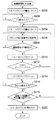
図4にCPU12で実行される「制御テーブルの確定処理」のルーチンを示す。
このフローチャートでは、まず、ステップ100で、印刷ジョブが開始されたことを確認する。印刷ジョブの開始が確認されると、ステップ100で肯定判断してステップ102に進み、ESS14から薄紙、普通紙、厚紙等の紙質情報を取得する。ESS14は、UI部32からの入力、マシンの設定値、厚さ検出センサ(図示せず)からの出力に基づいて、紙質情報を取得することができる。
(Control table confirmation processing)
FIG. 4 shows a “control table determination process” routine executed by the
In this flowchart, first, in
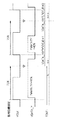
次に、ステップ104で、画像形成装置の各部をプリンタ制御部10により制御して、画像形成(プリント)動作を開始する。次のステップ106で、印刷ジョブのページ毎に出力されるページシンク(PS)信号が入力されたことを確認する。図6に示すように、PS信号は、画像処理においてページタイミングを生成し、主走査方向のライン毎に出力されるラインシンク(LS)信号のパルス数をカウントして、1ページの印画エリアが終了するとインアクティブになる。即ち、LS信号のパルス数をカウントして副走査の長さを判断できる。
Next, in step 104, each unit of the image forming apparatus is controlled by the
画像データ処理部18からPS信号が出力されると、ROS16にYMCK各色の画像データ信号(例えば、VDATA Y)が出力される。従って、PS信号の入力が確認されると、ステップ106で肯定判断してステップ108に進み、画素密度を計測する「画素密度計測処理」が実行される。この処理では、画素密度はレジスタ36(TCNT2)のカウント値として出力される。なお、「画素密度計測処理」の詳細については後述する。 When a PS signal is output from the image data processing unit 18, an image data signal for each color of YMCK (for example, VDATA Y) is output to the ROS 16. Therefore, when the input of the PS signal is confirmed, an affirmative determination is made in step 106 and the process proceeds to step 108, where “pixel density measurement processing” for measuring the pixel density is executed. In this processing, the pixel density is output as the count value of the register 36 (TCNT2). Details of the “pixel density measurement process” will be described later.
画素密度が計測される(TCNT2のカウント値が得られる)と、次のステップ110に進み、図9に示す表を参照して定着器制御テーブルを確定する。図9に示す表(FUSER CONT Table)は、紙質、TCNT2のカウント値、画素密度、及び濃度に対応した「定着器制御テーブル」を示すものである。図9に示す表は、メモリ30に格納されている。 When the pixel density is measured (a count value of TCNT2 is obtained), the process proceeds to the next step 110, and the fixing device control table is determined with reference to the table shown in FIG. The table (FUSER CONT Table) shown in FIG. 9 shows a “fixer control table” corresponding to paper quality, TCNT2 count value, pixel density, and density. The table shown in FIG. 9 is stored in the memory 30.
図9では、紙質は「薄紙、普通紙、厚紙」の3種類に分類され、各紙種毎に画素密度が「小、中、大」の3種類に分類されて、9種類の定着器制御テーブルが用意されている。画素密度が「小、中、大」は、濃度「薄、中、濃」に各々対応付けられる。画素密度の大小は、TCNT2のカウント値に閾値を設けることで判断される。閾値は定着器の特性に基づいて適宜設けられる。ここでは、TCNT2のカウント値が10以下の場合は画素密度「小」、11以上20以下の場合は画素密度「中」、21以上の場合は画素密度「大」とされている。 In FIG. 9, the paper quality is classified into three types “thin paper, plain paper, and thick paper”, and the pixel density is classified into three types “small, medium, and large” for each paper type, and nine types of fixing device control tables. Is prepared. The pixel density “small, medium, large” is associated with the density “light, medium, dark”, respectively. The magnitude of the pixel density is determined by providing a threshold value for the count value of TCNT2. The threshold is appropriately set based on the characteristics of the fixing device. Here, the pixel density is “small” when the count value of TCNT2 is 10 or less, the pixel density is “medium” when 11 or more and 20 or less, and the pixel density is “high” when 21 or more.
例えば、紙質が「普通紙」で且つ画素密度が「中」の場合には、表から「Table5」が選択され、定着器20は図3(B)及び(E)に示すスタンバイ状態(待機状態)とされる。また、紙質が「薄紙」で且つ画素密度が「大」の場合には、表から「Table3」が選択され、定着器20は図3(A)及び(D)に示す剥離優先の状態とされる。紙質が「薄紙」で且つ画素密度が「小」の場合には、表から「Table1」が選択され、「Table3」の場合より定着部でのピーク圧力が低下するように制御される。また、紙質が「厚紙」で且つ画素密度が「大」の場合には、表から「Table9」が選択され、定着器20は図3(C)及び(F)に示す定着優先の状態とされる。
For example, when the paper quality is “plain paper” and the pixel density is “medium”, “Table 5” is selected from the table, and the fixing
定着器制御テーブルが確定されるとステップ112に進み、ステップ112で、図10に示す表を参照してモータ制御パターンを確定し、次のステップ114で、モータ制御パターンに応じた制御信号を負荷制御部28に出力する。図10に示す表(MOTOR CONT Table)は、定着器制御テーブルに対応した「モータ制御パターン」を示すものである。図10に示す表は、メモリ30に格納されている。また、各制御パターンも、メモリ30に格納されている。
When the fixing device control table is determined, the process proceeds to step 112. At step 112, the motor control pattern is determined with reference to the table shown in FIG. 10, and at the next step 114, a control signal corresponding to the motor control pattern is loaded. The data is output to the
ここでは、図9のTable1乃至9に対応して、9種類のPatternA乃至Hが設けられている。例えば、ステップ110で定着器制御テーブルが「Table3」と確定されると、次のステップ112では「Table3」に対応した「PatterneC」がモータ制御パターンと確定される。モータ制御パターンが確定すると、メモリ30から確定したパターンが読み出され、このパターンに従ったモータ制御が実行される。 Here, nine types of Patterns A to H are provided corresponding to Tables 1 to 9 in FIG. For example, when the fixing device control table is determined as “Table3” in step 110, “PatterneC” corresponding to “Table3” is determined as the motor control pattern in the next step 112. When the motor control pattern is determined, the determined pattern is read from the memory 30, and motor control according to this pattern is executed.
なお、「パターン」とは、パルス数(モータの移動量)、励磁パターン、相に流す電流トルク等、ステッピングモータを制御するための制御パラメータを意味している。また、「パターン」には、他の形態から現在の形態へ移行するためのパラメータも含まれている。例えば、Table1からTable3に移行するためのモータのパラメータや、Table9からTable3に移行するためのモータのパラメータなどである。 The “pattern” means control parameters for controlling the stepping motor, such as the number of pulses (motor movement amount), the excitation pattern, and the current torque applied to the phase. The “pattern” also includes parameters for shifting from another form to the current form. For example, there are a motor parameter for shifting from Table 1 to Table 3, a motor parameter for shifting from Table 9 to Table 3, and the like.
次に、ステップ116で、PS信号がインアクティブになったことを確認する。PS信号がインアクティブになったことが確認されると、ステップ116で肯定判断してステップ118に進み、印刷ジョブが終了したか否かを判断する。印刷ジョブが終了していない場合は、次ページの処理があるため、ステップ106に戻って、PS信号が入力されたことを確認する。印刷ジョブが終了していれば、ここでルーチンを終了する。 Next, in step 116, it is confirmed that the PS signal becomes inactive. When it is confirmed that the PS signal has become inactive, an affirmative determination is made at step 116 and the process proceeds to step 118 to determine whether or not the print job has ended. If the print job has not ended, there is processing for the next page, so the process returns to step 106 to confirm that the PS signal has been input. If the print job has ended, the routine ends here.
図5には、図4のステップ108で実行される「画素密度計測処理」のサブルーチンを示す。サブルーチンが開始されると、まず、ステップ200で、レジスタ36(TCNT2)のカウント値をリセットし、次のステップ202で、LS信号が入力されたことを確認する。なお、用紙の定着器への到達を検出するレジセンサ(図示せず)の検出信号をトリガーとして、LS信号の入力を監視することができる。LS信号の入力が確認されると、ステップ202で肯定判断してステップ204に進み、レジスタ34(TCNT1)のカウント値をリセットする。LS信号が入力されると、次のステップ206で、クロック信号(VCLK)毎に画像データ信号(VDATA)を監視(取得)する。
FIG. 5 shows a subroutine of “pixel density measurement processing” executed in
図7は画像データ監視のタイミングを示すタイミングチャートであり、図8は画素密度が積算される様子を示すタイミングチャートである。図7及び図8に示すように、クロック信号に同期して設定された監視ポイント(矢印で示す)毎に、画像データ信号(VDATA Y)を確認する。図8では、クロック信号の立ち上りでデータの確定を行っている。なお、図ではY色の画像データ信号を確認しているが、Y色だけでなく、YMCK各色について画素密度の積算を行う。 FIG. 7 is a timing chart showing image data monitoring timing, and FIG. 8 is a timing chart showing how pixel densities are integrated. As shown in FIGS. 7 and 8, the image data signal (VDATA Y) is confirmed at each monitoring point (indicated by an arrow) set in synchronization with the clock signal. In FIG. 8, data is determined at the rising edge of the clock signal. Although the Y color image data signal is confirmed in the figure, the pixel density is integrated not only for the Y color but also for each color of YMCK.
この監視ポイントで、画像データ信号がハイレベル(H領域)にある場合には、TCNT1がアップカウントされ、カウント値が1増加する。画像データ信号がローレベル(L領域)にある場合には、TCNT1はアップカウントされない。TCNT1には予め閾値が設定されており、TCNT1のカウント値が設定された閾値を超える(オーバーフローする)と、TCNT2がアップカウントされ、カウント値が1増加する。従って、TCNT2のカウント値が大きいほど、画素密度が大きく、濃度が濃い(トナー量が多い)と判断される。なお、TCNT1はLS信号(1主走査ライン)毎にリセットされるので、TCNT2は1つのLS信号に対して1しか増加しない。 When the image data signal is at the high level (H region) at this monitoring point, TCNT1 is up-counted and the count value is increased by one. When the image data signal is at a low level (L region), TCNT1 is not up-counted. A threshold value is set in advance in TCNT1, and when the count value of TCNT1 exceeds the set threshold value (overflows), TCNT2 is up-counted and the count value increases by one. Therefore, it is determined that the larger the count value of TCNT2, the higher the pixel density and the higher the density (the more toner is). Since TCNT1 is reset for each LS signal (one main scanning line), TCNT2 increases only by 1 for one LS signal.
フローチャート(図5)に戻って説明すると、ステップ206で画像データ信号を取得した後、ステップ208で、画像データ信号がハイレベル(H領域)にあるか否かを判断する。H領域にある場合には、ステップ208で肯定判定してステップ210に進み、TCNT1をアップカウントする。一方、画像データ信号がL領域にある場合には、ステップ208で否定判定してステップ206に戻り、次の画像データ信号を取得する。 Returning to the flowchart (FIG. 5), after acquiring the image data signal in step 206, it is determined in step 208 whether or not the image data signal is at a high level (H region). If it is in the H region, an affirmative determination is made at step 208 and the routine proceeds to step 210 where TCNT1 is up-counted. On the other hand, if the image data signal is in the L region, a negative determination is made in step 208 and the flow returns to step 206 to acquire the next image data signal.
TCNT1をアップカウントした場合には、次にステップ212で、TCNT1がオーバーフローしていないか確認する。オーバーフローした場合は、ステップ212で肯定判定してステップ214に進み、TCNT2をアップカウントする。一方、TCNT1がオーバーフローしていない場合には、ステップ212で否定判定してステップ206に戻り、次の画像データ信号を取得する。 If TCNT1 has been up-counted, in step 212, it is confirmed whether TCNT1 has overflowed. If it overflows, an affirmative determination is made at step 212 and the routine proceeds to step 214 where TCNT2 is up-counted. On the other hand, if TCNT1 has not overflowed, a negative determination is made in step 212 and the process returns to step 206 to acquire the next image data signal.
TCNT2をアップカウントした場合には、次のステップ216で、次のLS信号が入力されたことを確認する。次のLS信号が入力されると、ステップ218に進み、LS信号の入力回数が所定値(例えば、50回)を超えたか否かを判断する。即ち、画像データ信号を監視する期間はLS信号の個数で管理されており、これにより画素密度が計測される領域(印字される用紙先端からの距離)が設定されている。 If TCNT2 has been up-counted, it is confirmed in the next step 216 that the next LS signal has been input. When the next LS signal is input, the process proceeds to step 218, and it is determined whether or not the number of times the LS signal is input exceeds a predetermined value (for example, 50 times). That is, the period during which the image data signal is monitored is managed by the number of LS signals, and an area in which the pixel density is measured (distance from the front end of the paper to be printed) is set.
LS信号の入力回数が所定値を超えた場合には、ステップ218で肯定判定してステップ220に進み、TCNT2のカウント値をメモリ30に記憶してルーチンを終了する。LS信号の入力回数が所定値を超えていない場合には、ステップ204に戻って処理を繰り返す。 If the number of times the LS signal has been input exceeds a predetermined value, an affirmative determination is made at step 218 and the routine proceeds to step 220 where the count value of TCNT2 is stored in the memory 30 and the routine is terminated. If the number of LS signal inputs does not exceed the predetermined value, the process returns to step 204 and the process is repeated.
(モータ故障検知)
本実施の形態に係る画像形成装置では、定着器20を駆動するモータ22に不具合があったり、モータを制御する負荷制御部28の回路基板に不具合があると、定着器20の可変機構が機能できなくなる。不具合を検知せず、用紙が定着器20に搬送されると、加熱ロールへの巻き付き、トナーの定着不良、紙づまり、紙しわ等が発生してしまう。従って、モータ故障検知機構を更に設けることが好ましい。
(Motor failure detection)
In the image forming apparatus according to the present embodiment, when the
図11(A)及び(B)はモータ故障検知機構を示す図である。
図11(A)の機構では、モータ22とモータ22の駆動電源80との間にヒューズ82が挿入され、直列に接続された抵抗84、86の一端がヒューズ82とモータ22との間に接続されると共に他端が接地されている。また、抵抗84、86の接続点はCPU12に接続されている。これにより、抵抗84、86の分圧がCPU12に入力される。なお、分圧が3V程度になるように、抵抗84、86の値が調整される。このようにCPU12で分圧電位をモニターすることで、ヒューズ82の断線、駆動電源80の不具合等によるモータ22の異常を検知することができる。
11A and 11B are views showing a motor failure detection mechanism.
In the mechanism of FIG. 11A, a
なお、異常を検知した場合には、検知内容、基板交換指示を不揮発性のメモリに格納した後、UI部32にアナウンスを表示し、定着器20の加熱ロールへの電力供給をシャットダウンする。これは用紙が加熱ロールへ巻き付き、加熱によって発煙発火することを防止するためである。また、検知内容等をメモリに格納しておくことで、後にサービス員がメンテナンス(トラブル調査)を行った際に、メモリ内容を確認できる。
When an abnormality is detected, the detected content and the board replacement instruction are stored in the nonvolatile memory, and then an announcement is displayed on the UI unit 32, and the power supply to the heating roll of the fixing
また、図11(B)の機構では、モータ22とモータ22の駆動電源80との間に抵抗88が挿入され、抵抗88前後での電位を比較するコンパレータ90が設けられている。コンパレータ90の出力端は、CPU12に接続されている。これにより、コンパレータ90の出力(パルス電圧)がCPU12に入力される。モータ22が通常の動作を行っているときは、電流はリップル状になり、CPU12において出力されるパルスの逓倍の周波数が確認できる。例えば、モータの1相あたりのコイルに異常が発生した場合には、周波数が乱れるので、これにより何らかの異常がモータ22に発生したことが確認できる。また、周波数が現れない場合には、モータ22が回転していないと判断でき、電気回路側になんらかの不具合が発生したと判断することができる。
In the mechanism of FIG. 11B, a
また、定着器20の周辺に、カムやギアの基準位置からのずれを検知する検知センサ(図1のセンサ26等)を配置して、モータ22の異常を検知することができる。例えば、定着器20がTable4の状態にある場合をホームポジションとして、センサ26から信号が入力されるようにする。印刷ジョブの開始前や用紙印刷間等の所定のタイミングでホームポジションに復帰するように制御し、そのタイミングでセンサ26からの検知信号が入力されない場合は、モータ22や負荷制御部28の回路基板に何らかの異常があると判断する。
In addition, a detection sensor (such as the sensor 26 in FIG. 1) that detects a deviation from the reference position of the cam or gear can be arranged around the fixing
なお、異常を検知した場合には、検知内容、基板交換指示を不揮発性のメモリに格納した後、UI部32にアナウンスを表示し、定着器20の加熱ロールへの電力供給をシャットダウンする。これは用紙が加熱ロールへ巻き付き、加熱によって発煙発火することを防止するためである。また、検知内容等をメモリに格納しておくことで、後にサービス員がメンテナンス(トラブル調査)を行った際に、メモリ内容を確認できる。
When an abnormality is detected, the detected content and the board replacement instruction are stored in the nonvolatile memory, and then an announcement is displayed on the UI unit 32, and the power supply to the heating roll of the fixing
なお、異常を検知した場合には、検知内容、基板交換指示を不揮発性のメモリに格納した後、UI部32にアナウンスを表示し、以下の処置を行う。ホームポジションから全く移動しない場合、厚紙では搬送速度を通常より遅くする。画素密度が特に高い場合には、搬送速度を2.5倍程度にする。これは、充分にトナーを用紙に定着させないとユーザへのトナー付着の危険性があるためである。厚紙で画素密度が低い場合には、用紙に消費される熱量分だけ搬送速度を遅くする。例えば、搬送速度を2倍程度にする。定着器20のピーク圧力を高くできないため、薄紙が指定された場合は印刷ジョブを終了してメッセージを表示する。或いは、薄紙の選択をできないように印刷ジョブの開始前にUI部32にアナウンス表示を行う。
If an abnormality is detected, the detected contents and the board replacement instruction are stored in the non-volatile memory, an announcement is displayed on the UI unit 32, and the following measures are taken. If the paper does not move at all from the home position, the transport speed for cardboard is slower than normal. When the pixel density is particularly high, the conveyance speed is set to about 2.5 times. This is because there is a risk of toner adhesion to the user unless the toner is sufficiently fixed on the paper. When the pixel density is low with thick paper, the transport speed is decreased by the amount of heat consumed by the paper. For example, the conveyance speed is about doubled. Since the peak pressure of the fixing
以上説明した通り、本実施の形態では、用紙の紙質に応じて接触ニップ域での圧力(ニップ圧)及び接触ニップ域の幅(ニップ幅)を制御すると共に、用紙の先端部分での画素密度の値に応じてニップ圧及びニップ幅を更に細かく制御して、最適な定着条件を設定することができ、紙質に拘わらず常に良好な定着画像を得ることができる。 As described above, in the present embodiment, the pressure in the contact nip area (nip pressure) and the width of the contact nip area (nip width) are controlled according to the paper quality of the paper, and the pixel density at the leading edge of the paper. The nip pressure and the nip width are further finely controlled in accordance with the value of, so that optimum fixing conditions can be set, and a good fixed image can always be obtained regardless of the paper quality.
また、本実施の形態では、ニップ幅を制御して加熱時間を変更することができ、厚紙の場合でも、搬送速度(プロセススピード)を遅くすることなく、熱供給量を制御することができる。 In this embodiment, the heating time can be changed by controlling the nip width, and even in the case of thick paper, the heat supply amount can be controlled without slowing down the conveyance speed (process speed).
上記の実施の形態では、カムを用いて接触ニップ域56の状態を変化させる可変機構を設けた例について説明したが、これは一例であり、可変機構はステッピングモータを用いて制御できるものであれば特に制限はない。例えば、ギヤや梃子(テコ)の原理によって可変させる可変機構や、加熱ロールの位置を前後にずらす可変機構を用いることもできる。
In the above embodiment, an example in which a variable mechanism for changing the state of the contact nip
また、連続プリントの際には、その都度Table5の待機状態まで戻っていると処理時間が長くなる。このため直前の形態から次の用紙に適した形態まで連続で動作を行う。これはパターンの中にそれぞれの形態(Table)からのモータ制御パターンを格納しており、そこから判断してCPUでモータの制御を行うことができるためである。 Further, in the case of continuous printing, the processing time becomes longer when returning to the standby state shown in Table 5 each time. Therefore, the operation is continuously performed from the immediately preceding form to the form suitable for the next sheet. This is because a motor control pattern from each form (Table) is stored in the pattern, and the CPU can be controlled by the CPU judging from the pattern.
10 プリンタ制御部
12 CPU
14 ESS
16 ROS
18 画像データ処理部
18 負荷制御部
20 定着器
22、24 モータ
26 センサ
28 負荷制御部
30 メモリ
32 UI部
34 レジスタ
36 レジスタ
40 加熱ロール
42 加熱ランプ
44 定着ベルト
46 コア
48 弾性層
50 圧力パッド
52 押圧部材
54 支持部材
56 接触ニップ域
58 回転軸
60 偏芯カム
62 連結部
64、66 アーム
68 固定部材
70 押圧部材
80 駆動電源
82 ヒューズ
84 抵抗
88 抵抗
90 コンパレータ
10
14 ESS
16 ROS
18 Image data processing unit 18
Claims (9)
前記第1の押圧部材に固定され且つ搬送方向に延びるアーム、前記搬送方向の入口側に配置され且つ回転により前記アームの一端を移動させる偏芯カム、及び前記搬送方向の出口側に配置され且つ荷重変化により伸縮して前記アームの他端を押圧する第2の押圧部材を備え、前記偏芯カムの回転及び前記第2の押圧部材に掛かる荷重変化に応じた前記アームの移動により、前記接触ニップ域のニップ圧及びニップ幅の少なくとも一方を変化させる可変機構と、
前記偏芯カムを回転させると共に前記第2の押圧部材に掛かる荷重を増減して、前記可変機構を駆動する駆動手段と、
画像を形成する用紙の紙質情報を含む画像形成条件に応じて前記搬送方向の圧力分布が変化するように、前記駆動手段を制御する制御手段と、
を備えた画像形成装置。 An endless belt is disposed in pressure contact with the heating roll by a first pressing member having a pressure pad made of an elastic body, and a sheet is passed through a contact nip area formed between the heating roll and the endless belt, A fixing device for heating and pressure-fixing an unfixed image on the paper;
An arm fixed to the first pressing member and extending in the transport direction, an eccentric cam disposed on the entrance side in the transport direction and moving one end of the arm by rotation, and disposed on the exit side in the transport direction; A second pressing member that expands and contracts due to a load change and presses the other end of the arm, and the contact is caused by the rotation of the eccentric cam and the movement of the arm according to a load change applied to the second pressing member; A variable mechanism that changes at least one of the nip pressure and the nip width of the nip region;
Driving means for rotating the eccentric cam and increasing / decreasing a load applied to the second pressing member to drive the variable mechanism;
Control means for controlling the driving means so that the pressure distribution in the transport direction changes according to image forming conditions including paper quality information of paper on which an image is formed;
An image forming apparatus.
前記制御手段は、前記設定手段で設定された制御条件に基づいて前記駆動手段を制御する請求項1に記載の画像形成装置。 Information acquisition means for acquiring the paper quality information of the paper, measurement means for measuring the pixel density in a predetermined print area of the input image data, paper quality information acquired by the information acquisition means, and measurement by the measurement means Setting means for setting control conditions according to the pixel density obtained,
The image forming apparatus according to claim 1, wherein the control unit controls the driving unit based on a control condition set by the setting unit.
Priority Applications (1)
| Application Number | Priority Date | Filing Date | Title |
|---|---|---|---|
| JP2006120845A JP4972985B2 (en) | 2006-04-25 | 2006-04-25 | Image forming apparatus |
Applications Claiming Priority (1)
| Application Number | Priority Date | Filing Date | Title |
|---|---|---|---|
| JP2006120845A JP4972985B2 (en) | 2006-04-25 | 2006-04-25 | Image forming apparatus |
Publications (2)
| Publication Number | Publication Date |
|---|---|
| JP2007293037A JP2007293037A (en) | 2007-11-08 |
| JP4972985B2 true JP4972985B2 (en) | 2012-07-11 |
Family
ID=38763721
Family Applications (1)
| Application Number | Title | Priority Date | Filing Date |
|---|---|---|---|
| JP2006120845A Expired - Fee Related JP4972985B2 (en) | 2006-04-25 | 2006-04-25 | Image forming apparatus |
Country Status (1)
| Country | Link |
|---|---|
| JP (1) | JP4972985B2 (en) |
Families Citing this family (4)
| Publication number | Priority date | Publication date | Assignee | Title |
|---|---|---|---|---|
| JP4947020B2 (en) * | 2008-09-26 | 2012-06-06 | 富士ゼロックス株式会社 | Fixing device and image forming apparatus using the same |
| JP4978648B2 (en) * | 2009-03-26 | 2012-07-18 | ブラザー工業株式会社 | Fixing device |
| JP5471201B2 (en) | 2009-09-04 | 2014-04-16 | 株式会社リコー | Heat fixing device and image forming apparatus |
| JP6160238B2 (en) * | 2013-05-21 | 2017-07-12 | コニカミノルタ株式会社 | Image forming apparatus, roller control method, and computer program |
Family Cites Families (7)
| Publication number | Priority date | Publication date | Assignee | Title |
|---|---|---|---|---|
| JPS62135865A (en) * | 1985-12-10 | 1987-06-18 | Fuji Xerox Co Ltd | Fixing device |
| JPH10161470A (en) * | 1996-12-03 | 1998-06-19 | Fuji Xerox Co Ltd | Image forming device |
| JP3959556B2 (en) * | 1997-02-17 | 2007-08-15 | 富士ゼロックス株式会社 | Fixing device |
| JP2001337553A (en) * | 2000-05-26 | 2001-12-07 | Hitachi Koki Co Ltd | Fixing device for electrophotographic device |
| JP4181494B2 (en) * | 2003-12-26 | 2008-11-12 | 株式会社沖データ | Fixing apparatus and image forming apparatus |
| KR20050113761A (en) * | 2004-05-31 | 2005-12-05 | 삼성전자주식회사 | Temperature control apparatus for fixing unit, and speed control apparatus for fan, and control methods thereof and image forming apparatus |
| JP2006091501A (en) * | 2004-09-24 | 2006-04-06 | Canon Inc | Fixing device |
-
2006
- 2006-04-25 JP JP2006120845A patent/JP4972985B2/en not_active Expired - Fee Related
Also Published As
| Publication number | Publication date |
|---|---|
| JP2007293037A (en) | 2007-11-08 |
Similar Documents
| Publication | Publication Date | Title |
|---|---|---|
| US8588639B2 (en) | Fixing device and image forming apparatus | |
| US7593658B2 (en) | Image forming apparatus | |
| US7623805B2 (en) | Image heating apparatus and image forming apparatus | |
| US8494388B2 (en) | Image forming apparatus with controlled heating width | |
| JP4871633B2 (en) | Image forming apparatus | |
| JP4972985B2 (en) | Image forming apparatus | |
| US10401766B2 (en) | Image forming apparatus and image forming method with temperature and power-based productivity rate selection | |
| JP6833377B2 (en) | Image forming device and fixing device | |
| JP4306557B2 (en) | Image forming system | |
| US6724493B1 (en) | Information processing apparatus, information processing method, image output system, electric power consumption control method for image output system, and storage medium therefor | |
| JP7116361B2 (en) | IMAGE FORMING APPARATUS AND IMAGE FORMING APPARATUS CONTROL METHOD | |
| JP4594013B2 (en) | Image forming apparatus | |
| JP2006023377A (en) | Image forming apparatus | |
| JP2002352936A (en) | Heating device and imaging device | |
| US6985689B2 (en) | Image heating apparatus having multiple rotatable members and temperature detecting element | |
| JP2000330408A (en) | Fixing device, image forming device and control method therefor | |
| US8238775B2 (en) | Image heating apparatus | |
| KR100303661B1 (en) | Method for controlling temperature of fusing device | |
| JP2009048074A (en) | Fixing device and image forming apparatus | |
| JP4615320B2 (en) | Image forming apparatus and control method | |
| JP2000309143A (en) | Device and method for information processing, image output system, method for controlling power consumption thereof, and memory medium | |
| JP2005024667A (en) | Image forming apparatus | |
| JP6841065B2 (en) | Fixing device, image forming device, abnormality occurrence judgment device, and program | |
| JP2003280447A (en) | Image forming apparatus | |
| US20230168614A1 (en) | Image forming apparatus |
Legal Events
| Date | Code | Title | Description |
|---|---|---|---|
| A621 | Written request for application examination |
Free format text: JAPANESE INTERMEDIATE CODE: A621 Effective date: 20090212 |
|
| A977 | Report on retrieval |
Free format text: JAPANESE INTERMEDIATE CODE: A971007 Effective date: 20110707 |
|
| A131 | Notification of reasons for refusal |
Free format text: JAPANESE INTERMEDIATE CODE: A131 Effective date: 20110712 |
|
| A521 | Request for written amendment filed |
Free format text: JAPANESE INTERMEDIATE CODE: A523 Effective date: 20110908 |
|
| TRDD | Decision of grant or rejection written | ||
| A01 | Written decision to grant a patent or to grant a registration (utility model) |
Free format text: JAPANESE INTERMEDIATE CODE: A01 Effective date: 20120313 |
|
| A01 | Written decision to grant a patent or to grant a registration (utility model) |
Free format text: JAPANESE INTERMEDIATE CODE: A01 |
|
| A61 | First payment of annual fees (during grant procedure) |
Free format text: JAPANESE INTERMEDIATE CODE: A61 Effective date: 20120326 |
|
| R150 | Certificate of patent or registration of utility model |
Ref document number: 4972985 Country of ref document: JP Free format text: JAPANESE INTERMEDIATE CODE: R150 Free format text: JAPANESE INTERMEDIATE CODE: R150 |
|
| FPAY | Renewal fee payment (event date is renewal date of database) |
Free format text: PAYMENT UNTIL: 20150420 Year of fee payment: 3 |
|
| S533 | Written request for registration of change of name |
Free format text: JAPANESE INTERMEDIATE CODE: R313533 |
|
| R350 | Written notification of registration of transfer |
Free format text: JAPANESE INTERMEDIATE CODE: R350 |
|
| LAPS | Cancellation because of no payment of annual fees |