JP7224870B2 - image forming device - Google Patents
image forming device Download PDFInfo
- Publication number
- JP7224870B2 JP7224870B2 JP2018217145A JP2018217145A JP7224870B2 JP 7224870 B2 JP7224870 B2 JP 7224870B2 JP 2018217145 A JP2018217145 A JP 2018217145A JP 2018217145 A JP2018217145 A JP 2018217145A JP 7224870 B2 JP7224870 B2 JP 7224870B2
- Authority
- JP
- Japan
- Prior art keywords
- envelope
- pressure
- fixing
- image forming
- unit
- Prior art date
- Legal status (The legal status is an assumption and is not a legal conclusion. Google has not performed a legal analysis and makes no representation as to the accuracy of the status listed.)
- Active
Links
Images


Classifications
-
- G—PHYSICS
- G03—PHOTOGRAPHY; CINEMATOGRAPHY; ANALOGOUS TECHNIQUES USING WAVES OTHER THAN OPTICAL WAVES; ELECTROGRAPHY; HOLOGRAPHY
- G03G—ELECTROGRAPHY; ELECTROPHOTOGRAPHY; MAGNETOGRAPHY
- G03G15/00—Apparatus for electrographic processes using a charge pattern
- G03G15/20—Apparatus for electrographic processes using a charge pattern for fixing, e.g. by using heat
- G03G15/2003—Apparatus for electrographic processes using a charge pattern for fixing, e.g. by using heat using heat
- G03G15/2014—Apparatus for electrographic processes using a charge pattern for fixing, e.g. by using heat using heat using contact heat
- G03G15/2064—Apparatus for electrographic processes using a charge pattern for fixing, e.g. by using heat using heat using contact heat combined with pressure
-
- G—PHYSICS
- G03—PHOTOGRAPHY; CINEMATOGRAPHY; ANALOGOUS TECHNIQUES USING WAVES OTHER THAN OPTICAL WAVES; ELECTROGRAPHY; HOLOGRAPHY
- G03G—ELECTROGRAPHY; ELECTROPHOTOGRAPHY; MAGNETOGRAPHY
- G03G15/00—Apparatus for electrographic processes using a charge pattern
- G03G15/20—Apparatus for electrographic processes using a charge pattern for fixing, e.g. by using heat
- G03G15/2003—Apparatus for electrographic processes using a charge pattern for fixing, e.g. by using heat using heat
- G03G15/2014—Apparatus for electrographic processes using a charge pattern for fixing, e.g. by using heat using heat using contact heat
- G03G15/2039—Apparatus for electrographic processes using a charge pattern for fixing, e.g. by using heat using heat using contact heat with means for controlling the fixing temperature
-
- G—PHYSICS
- G03—PHOTOGRAPHY; CINEMATOGRAPHY; ANALOGOUS TECHNIQUES USING WAVES OTHER THAN OPTICAL WAVES; ELECTROGRAPHY; HOLOGRAPHY
- G03G—ELECTROGRAPHY; ELECTROPHOTOGRAPHY; MAGNETOGRAPHY
- G03G15/00—Apparatus for electrographic processes using a charge pattern
- G03G15/20—Apparatus for electrographic processes using a charge pattern for fixing, e.g. by using heat
- G03G15/2003—Apparatus for electrographic processes using a charge pattern for fixing, e.g. by using heat using heat
- G03G15/2014—Apparatus for electrographic processes using a charge pattern for fixing, e.g. by using heat using heat using contact heat
- G03G15/2053—Structural details of heat elements, e.g. structure of roller or belt, eddy current, induction heating
-
- G—PHYSICS
- G03—PHOTOGRAPHY; CINEMATOGRAPHY; ANALOGOUS TECHNIQUES USING WAVES OTHER THAN OPTICAL WAVES; ELECTROGRAPHY; HOLOGRAPHY
- G03G—ELECTROGRAPHY; ELECTROPHOTOGRAPHY; MAGNETOGRAPHY
- G03G15/00—Apparatus for electrographic processes using a charge pattern
- G03G15/50—Machine control of apparatus for electrographic processes using a charge pattern, e.g. regulating differents parts of the machine, multimode copiers, microprocessor control
- G03G15/5016—User-machine interface; Display panels; Control console
-
- G—PHYSICS
- G03—PHOTOGRAPHY; CINEMATOGRAPHY; ANALOGOUS TECHNIQUES USING WAVES OTHER THAN OPTICAL WAVES; ELECTROGRAPHY; HOLOGRAPHY
- G03G—ELECTROGRAPHY; ELECTROPHOTOGRAPHY; MAGNETOGRAPHY
- G03G15/00—Apparatus for electrographic processes using a charge pattern
- G03G15/65—Apparatus which relate to the handling of copy material
- G03G15/6552—Means for discharging uncollated sheet copy material, e.g. discharging rollers, exit trays
-
- G—PHYSICS
- G03—PHOTOGRAPHY; CINEMATOGRAPHY; ANALOGOUS TECHNIQUES USING WAVES OTHER THAN OPTICAL WAVES; ELECTROGRAPHY; HOLOGRAPHY
- G03G—ELECTROGRAPHY; ELECTROPHOTOGRAPHY; MAGNETOGRAPHY
- G03G15/00—Apparatus for electrographic processes using a charge pattern
- G03G15/65—Apparatus which relate to the handling of copy material
- G03G15/6555—Handling of sheet copy material taking place in a specific part of the copy material feeding path
- G03G15/6573—Feeding path after the fixing point and up to the discharge tray or the finisher, e.g. special treatment of copy material to compensate for effects from the fixing
-
- G—PHYSICS
- G03—PHOTOGRAPHY; CINEMATOGRAPHY; ANALOGOUS TECHNIQUES USING WAVES OTHER THAN OPTICAL WAVES; ELECTROGRAPHY; HOLOGRAPHY
- G03G—ELECTROGRAPHY; ELECTROPHOTOGRAPHY; MAGNETOGRAPHY
- G03G15/00—Apparatus for electrographic processes using a charge pattern
- G03G15/65—Apparatus which relate to the handling of copy material
- G03G15/6588—Apparatus which relate to the handling of copy material characterised by the copy material, e.g. postcards, large copies, multi-layered materials, coloured sheet material
- G03G15/6594—Apparatus which relate to the handling of copy material characterised by the copy material, e.g. postcards, large copies, multi-layered materials, coloured sheet material characterised by the format or the thickness, e.g. endless forms
-
- B—PERFORMING OPERATIONS; TRANSPORTING
- B65—CONVEYING; PACKING; STORING; HANDLING THIN OR FILAMENTARY MATERIAL
- B65H—HANDLING THIN OR FILAMENTARY MATERIAL, e.g. SHEETS, WEBS, CABLES
- B65H2301/00—Handling processes for sheets or webs
- B65H2301/10—Selective handling processes
- B65H2301/14—Selective handling processes of batches of material of different characteristics
- B65H2301/142—Selective handling processes of batches of material of different characteristics of different thickness
- B65H2301/1422—Sheet or envelope
-
- G—PHYSICS
- G03—PHOTOGRAPHY; CINEMATOGRAPHY; ANALOGOUS TECHNIQUES USING WAVES OTHER THAN OPTICAL WAVES; ELECTROGRAPHY; HOLOGRAPHY
- G03G—ELECTROGRAPHY; ELECTROPHOTOGRAPHY; MAGNETOGRAPHY
- G03G2215/00—Apparatus for electrophotographic processes
- G03G2215/00362—Apparatus for electrophotographic processes relating to the copy medium handling
- G03G2215/00367—The feeding path segment where particular handling of the copy medium occurs, segments being adjacent and non-overlapping. Each segment is identified by the most downstream point in the segment, so that for instance the segment labelled "Fixing device" is referring to the path between the "Transfer device" and the "Fixing device"
- G03G2215/00417—Post-fixing device
- G03G2215/00421—Discharging tray, e.g. devices stabilising the quality of the copy medium, postfixing-treatment, inverting, sorting
-
- G—PHYSICS
- G03—PHOTOGRAPHY; CINEMATOGRAPHY; ANALOGOUS TECHNIQUES USING WAVES OTHER THAN OPTICAL WAVES; ELECTROGRAPHY; HOLOGRAPHY
- G03G—ELECTROGRAPHY; ELECTROPHOTOGRAPHY; MAGNETOGRAPHY
- G03G2215/00—Apparatus for electrophotographic processes
- G03G2215/00362—Apparatus for electrophotographic processes relating to the copy medium handling
- G03G2215/00443—Copy medium
- G03G2215/00514—Envelopes
-
- G—PHYSICS
- G03—PHOTOGRAPHY; CINEMATOGRAPHY; ANALOGOUS TECHNIQUES USING WAVES OTHER THAN OPTICAL WAVES; ELECTROGRAPHY; HOLOGRAPHY
- G03G—ELECTROGRAPHY; ELECTROPHOTOGRAPHY; MAGNETOGRAPHY
- G03G2215/00—Apparatus for electrophotographic processes
- G03G2215/00362—Apparatus for electrophotographic processes relating to the copy medium handling
- G03G2215/00535—Stable handling of copy medium
- G03G2215/00556—Control of copy medium feeding
- G03G2215/00586—Control of copy medium feeding duplex mode
-
- G—PHYSICS
- G03—PHOTOGRAPHY; CINEMATOGRAPHY; ANALOGOUS TECHNIQUES USING WAVES OTHER THAN OPTICAL WAVES; ELECTROGRAPHY; HOLOGRAPHY
- G03G—ELECTROGRAPHY; ELECTROPHOTOGRAPHY; MAGNETOGRAPHY
- G03G2215/00—Apparatus for electrophotographic processes
- G03G2215/00362—Apparatus for electrophotographic processes relating to the copy medium handling
- G03G2215/00535—Stable handling of copy medium
- G03G2215/00717—Detection of physical properties
- G03G2215/00742—Detection of physical properties of sheet weight
Description
本発明は、電子写真方式を用いたプリンタ、複写機、ファクシミリあるいは複合機などの画像形成装置に関する。 The present invention relates to an image forming apparatus such as a printer, a copying machine, a facsimile machine, or a multifunction machine using an electrophotographic system.
電子写真方式などの画像形成装置では、転写部で記録材上にトナー像が形成された後、トナー像を記録材に定着させるために、記録材が定着装置に搬送される。定着装置に搬送された記録材が定着ローラと加圧ローラとにより形成される定着ニップを通過する際に、記録材に形成されたトナー像が加熱、加圧されることにより記録材に定着される。最近では、記録材として普通紙、厚紙、ラフ紙、エンボス紙、コート紙等の紙に印刷する以外にも、封筒に印刷するために画像形成装置が用いられている(特許文献1)。特許文献1に記載の装置では、定着装置によりトナー像を普通紙に定着させる場合と封筒に定着させる場合とで、定着ニップのニップ圧を異なる値に設定している。 2. Description of the Related Art In an electrophotographic image forming apparatus, after a toner image is formed on a recording material in a transfer unit, the recording material is conveyed to a fixing device to fix the toner image on the recording material. When the recording material conveyed to the fixing device passes through a fixing nip formed by a fixing roller and a pressure roller, the toner image formed on the recording material is heated and pressed to be fixed on the recording material. be. Recently, in addition to printing on paper such as plain paper, thick paper, rough paper, embossed paper, and coated paper as recording materials, image forming apparatuses are used to print on envelopes (Patent Document 1). In the apparatus disclosed in Patent Document 1, the nip pressure of the fixing nip is set to different values depending on whether the fixing device fixes a toner image on plain paper or an envelope.
従来では、封筒の定着時に宛名面と非宛名面とで同じニップ圧が設定され、それにより、封筒の宛名面の定着に伴って封筒に段差跡(封筒しわ)が生じるか、封筒の非宛名面の定着に伴ってトナー像の定着不良が生じるかする虞があった。これは、封筒が袋状に形成され、紙と紙とが貼り合わされている箇所とそれ以外の箇所とで厚みが異なる故に、定着ニップを通過する際にそれらの箇所で実際に封筒にかかる圧力が異なり得るからである。かといって、封筒の場合、宛名面と非宛名面の両方におけるトナー像の定着に最適な共通のニップ圧を設定することは難しく、例え可能であったとしても調整に時間がかかり面倒であった。そこで、従来から封筒の宛名面と非宛名面とにおけるトナー像の定着を適切に行い得るものが望まれていたが、未だそのようなものは提案されていない。 Conventionally, the same nip pressure is set for the address side and the non-address side when the envelope is fused. There is a fear that fixing failure of the toner image may occur with the fixing of the surface. This is because the envelope is formed in a bag shape, and the thickness differs between the portion where the paper and the paper are stuck together and the other portions, so the pressure actually applied to the envelope when passing through the fixing nip. can be different. However, in the case of envelopes, it is difficult to set the optimum common nip pressure for fixing the toner image on both the address side and the non-address side. rice field. Therefore, conventionally, there has been a demand for a device capable of appropriately fixing a toner image on the address side and the non-address side of an envelope, but no such device has been proposed yet.
本発明は上記問題に鑑みてなされ、封筒の宛名面と非宛名面とにおけるトナー像の定着を適切に行うことが可能な画像形成装置の提供を目的とする。 SUMMARY OF THE INVENTION It is an object of the present invention to provide an image forming apparatus capable of appropriately fixing a toner image on the address side and the non-address side of an envelope.
本発明の一実施形態に係る画像形成装置は、紙と紙とが互いに貼り合わされた領域である貼り合わせ部を含む封筒の第一面と、前記貼り合わせ部を含まず、且つフラップを有する、前記第一面と反対側の前記封筒の第二面とに対し画像を形成可能な画像形成装置において、封筒にトナー像を形成可能な画像形成部と、定着部材と、前記定着部材を加熱する加熱部と、前記定着部材に当接して前記封筒が挟持搬送される定着ニップを形成する加圧部材を有し、熱及び圧により前記封筒にトナー像を定着させる定着装置と、前記定着部材と前記加圧部材間の圧力を調整可能な加圧調整機構と、前記封筒の前記第二面に画像を形成する指示が入力された場合には、前記加圧調整機構の圧力を第一の圧力に調整し、前記封筒の前記第一面に画像を形成する指示が入力された場合には、前記加圧調整機構の圧力を前記第一の圧力よりも大きい第二の圧力に調整することにより、トナー像が前記封筒に定着するように前記加圧調整機構を制御する制御部と、を備える、ことを特徴とする。 An image forming apparatus according to an embodiment of the present invention includes a first surface of an envelope including a bonded portion, which is an area in which sheets of paper are bonded together , and a flap that does not include the bonded portion. In an image forming apparatus capable of forming an image on the first side and the second side of the envelope on the opposite side, an image forming section capable of forming a toner image on the envelope, a fixing member, and the fixing member are heated. a fixing device that has a heating unit and a pressure member that forms a fixing nip in which the envelope is nipped and conveyed in contact with the fixing member, and that fixes the toner image to the envelope by heat and pressure; and the fixing member. a pressure adjustment mechanism capable of adjusting the pressure between the pressure members; and a first pressure when an instruction to form an image on the second surface of the envelope is input. and when an instruction to form an image on the first side of the envelope is input, adjusting the pressure of the pressure adjustment mechanism to a second pressure higher than the first pressure and a control unit for controlling the pressure adjustment mechanism so that the toner image is fixed on the envelope.
本発明によれば、封筒の宛名面と非宛名面とにおけるトナー像の定着を適切に行うことが容易にできる。 According to the present invention, it is possible to easily and appropriately fix a toner image on the address side and the non-address side of an envelope.
<画像形成装置>
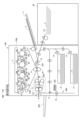
まず、本実施形態の画像形成装置について、図1を用いて説明する。図1に示す画像形成装置100は、電子写真方式のタンデム型のフルカラープリンタである。画像形成装置100は、それぞれイエロー、マゼンタ、シアン、ブラックの画像を形成する画像形成部PY、PM、PC、PKを有する。画像形成装置100は、装置本体100aに接続された原稿読取装置(不図示)あるいは装置本体100aに対し通信可能に接続されたパーソナルコンピュータ等の外部端末からの画像データに応じて、トナー像を記録材に形成する。本実施形態では、記録材である封筒Sに対しトナー像を形成可能である。
<Image forming apparatus>
First, the image forming apparatus of this embodiment will be described with reference to FIG. The
図1に示すように、画像形成部PY、PM、PC、PKは装置本体100a内において、中間転写ベルト8の移動方向に沿って並べて配置されている。中間転写ベルト8は複数のローラに張架されて、矢印R2方向に走行するように構成されている。そして、中間転写ベルト8は一次転写されたトナー像を担持して搬送する。中間転写ベルト8を張架する二次転写内ローラ9と中間転写ベルト8を挟んで対向する位置には、二次転写外ローラ10が配置され、中間転写ベルト8上のトナー像を封筒Sに転写する二次転写部T2を構成している。二次転写部T2の記録材搬送方向下流には、定着装置200が配置されている。
As shown in FIG. 1, the image forming units PY, PM, PC, and PK are arranged side by side along the moving direction of the
画像形成装置100の下部には、封筒Sが載置されたカセット12が配置されている。封筒Sは、搬送ローラ13によりカセット12から搬送路601に供給される。その後、レジストレーションローラ14が後述するようにして中間転写ベルト8上に形成されたトナー像と同期して回転開始されることにより、封筒Sは二次転写部T2に搬送される。なお、カセット12はサイズや厚さの異なる封筒Sを載置可能に複数が配置されていてよく、その場合、複数(ここでは二個)のカセット12のいずれかから選択的に封筒Sが搬送される。また、カセット12に載置された封筒Sに限らず、手差しトレイ11に載置された封筒Sが搬送されてもよいし、あるいは装置本体100aに接続された載置装置20内に載置されている封筒Sが搬送されてもよい。なお、本実施形態の場合、手差しトレイ11や載置装置20(第一載置部に相当)の封筒Sは上面側にトナー像が形成されるように、表裏が載置状態のまま二次転写部T2に搬送される。他方、カセット12(第二載置部に相当)の封筒Sは下面側にトナー像が形成されるように、表裏が載置状態と逆になって二次転写部T2に搬送される。
A
画像形成装置100が備える4つの画像形成部PY、PM、PC、PKは、現像色が異なることを除いて実質的に同一の構成を有する。したがって、ここでは代表してイエローの画像形成部PYについて説明し、その他の画像形成部については説明を省略する。画像形成部PYには、感光ドラム1Yが配設されている。感光ドラム1Yは、矢印R1方向に回転駆動される。感光ドラム1Yの周囲には帯電装置2Y、露光装置3、現像装置4Y、一次転写ローラ5Y、クリーニング装置6Yが配置されている。
The four image forming units PY, PM, PC, and PK provided in the
画像形成動作が開始された場合、まず回転する感光ドラム1Yの表面が帯電装置2Yによって一様に帯電される。帯電装置2Yは、例えばコロナ放電に伴う荷電粒子を照射して感光ドラム1Yを一様な負極性の暗部電位に帯電させるコロナ帯電器などである。次いで、感光ドラム1Yは、露光装置3から発せられる画像データに対応したレーザ光により走査露光される。これにより、感光ドラム1Yの表面に画像データに応じた静電潜像が形成される。感光ドラム1Yに形成された静電潜像は、現像装置4Y内に収容されているトナー(現像剤)によって顕像化され、可視像であるトナー像となる。
When the image forming operation is started, first, the surface of the rotating photosensitive drum 1Y is uniformly charged by the
感光ドラム1Yに形成されたトナー像は、中間転写ベルト8を挟んで配置される一次転写ローラ5Yとの間で構成される一次転写部にて、中間転写ベルト8に一次転写される。この際、一次転写ローラ5Yには一次転写バイアスが印加される。一次転写後に感光ドラム1Yの表面に残ったトナーは、クリーニング装置6Yによって除去される。
The toner image formed on the photosensitive drum 1Y is primarily transferred onto the
このような動作をイエロー、マゼンタ、シアン、ブラックの各画像形成部PY~PKで順次行い、中間転写ベルト8上で4色のトナー像を重ね合わせる。その後、トナー像の形成タイミングにあわせて手差しトレイ11やカセット12あるいは載置装置20に載置された封筒Sが搬送路601を通じて二次転写部T2に搬送される。そして、二次転写外ローラ10に二次転写バイアスを印加することにより、中間転写ベルト8上に形成されたフルカラーのトナー像が封筒Sに一括して二次転写される。
Such an operation is sequentially performed in each of the yellow, magenta, cyan, and black image forming portions PY to PK, and four color toner images are superimposed on the
次いで、二次転写部T2を通過した封筒Sは、ガイド部材500により支持されて、定着装置200に向け搬送される。ガイド部材500は、直前の二次転写部T2通過時にトナー像が形成された面の反対面側で封筒Sを支持して、定着装置200に向け封筒Sを案内する。定着部としての定着装置200では、封筒Sが挟持搬送されることに伴い、トナー像が加熱、加圧されて封筒Sに定着される。
After passing through the secondary transfer portion T2, the envelope S is supported by the
<定着装置>
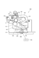
定着装置200について、図2を用いて説明する。図2に示す定着装置200は、ツインベルト方式の定着装置である。この定着装置200は、図2に示すように、上フレーム201に組み立てられた無端状の定着ベルト130に、下フレーム202に組み立てられた無端状の加圧ベルト120を当接させて定着ニップUを形成している。即ち、本実施形態の場合、加圧ベルト120がニップ形成部材に相当する。定着部材としての定着ベルト130は、枠体115に軸支された駆動ローラ131とテンションローラ132とに所定張力で掛け渡されて、駆動ローラ131の回転によって循環回転される。駆動ローラ131は定着ベルト130の内面を支持して定着ニップUに圧力を発生させる機能を有し、テンションローラ132は定着ベルト130にベルトテンションを付与する機能を有する。定着ベルト130の内側には、例えばステンレス鋼で形成された定着パッド133が配置されている。定着パッド133は、定着ベルト130を所定圧で加圧パッド123に向かって押し当てることで、駆動ローラ131とともに定着ニップUを形成している。
<Fixing device>
Fixing
本実施形態の場合、下フレーム202は上フレーム201に対し接離可能に設けられ、加圧モータ700の回転により駆動される加圧調整機構800によって移動される。加圧調整機構800は加圧モータ700の回転方向と回転量が変えられると、加圧ベルト120と定着ベルト130との間に生じる加圧力を可変し得る。これに応じ、定着ニップUのニップ圧が所望の圧力に調整可能となっている。加圧調整機構800としては、例えばベースフレームに取り付けられ加圧カムを両端に有する加圧カム軸と、加圧カム軸に加圧モータ700の回転を伝達する加圧ギアと、下フレーム202を上フレーム201側に付勢する加圧バネ等を有するものが挙げられる。
In the case of this embodiment, the
定着装置200では、定着ベルト130が誘導加熱装置150(例えばIHヒータ)によって電磁誘導加熱される。誘導加熱装置150は、定着ベルト130の外周面との間に所定の隙間を空けるようにして配設されている。誘導加熱装置150は、図示を省略したが、例えばリッツ線などの電線を巻回した励磁コイルと、外側磁性体コアとを有する。励磁コイルは交流電流が印加されると、交流磁界(磁束)を発生する。励磁コイルが交流磁界を発生することで、定着ベルト130が誘導加熱される。そして、定着ベルト130を効率よく誘導加熱するために、交流磁界を遮蔽可能なフェライト等の高透磁率の部材により形成される外側磁性体コアが励磁コイルを覆うように配設されている。なお、定着ベルト130には、表面温度を検出するための検出手段としての温度センサ210(例えばサーミスタ)が配設されている。
In the
加圧ベルト120は、下フレーム202に軸支された加圧ローラ121とテンションローラ122とに所定張力で架け渡されて、定着ベルト130の回転により従動回転される。加圧ベルト120の内側には、例えばシリコンゴムで形成された加圧パッド123が配置される。加圧パッド123は、加圧ベルト120を所定圧で定着パッド133に向かって押し当てることにより、加圧ベルト120と加圧ローラ121との間に定着ニップUが形成されるのを補助している。こうした定着ニップUを通過した封筒Sは、定着排紙ローラ対140によって定着装置200外へ排出される。なお、加圧ローラ121は、加圧ローラ121の長手方向に均一な定着ニップUを形成するために、回転軸線方向の中央部から両端部へ向かって連続的に直径が小さくなるように外周面が形成されたクラウン形状のローラであるのが好ましい。
The
図1の説明に戻り、画像形成装置100は封筒Sの両面を印刷可能である。片面印刷の場合、一面側にトナー像が定着された封筒Sは、排紙ローラ15によって装置本体100a外に設けられた排紙トレイ602上に排出される。他方、両面印刷の場合、一面側にトナー像が定着された封筒Sは、トナー像の定着後に続けて二面目にトナー像を形成するために、順回転する搬送ローラ16により両面搬送路600へと搬送される。そして、搬送ローラ16は、封筒Sの搬送方向後端が切り替え部17に達したタイミングで逆回転する。封筒Sは搬送ローラ16の逆回転によって両面搬送路600で先後端が入れ替えられ、レジストレーションローラ14に向けて搬送路601を再搬送される(所謂、スイッチバック搬送)。この場合、搬送路601を再搬送される封筒Sは、二次転写部T2においてトナー像が定着されていない他方の面(一面側と反対の二面側)が中間転写ベルト8側を向くように、一面目と二面目とが入れ替えられている(反転されている)。以後は、片面印刷の場合と同様の過程を経て二面目にトナー像の定着が行われて、排紙ローラ15によって装置本体100a外の排紙トレイ602上に排出される。なお、両面搬送路600と排紙ローラ15と切り替え部17とで構成される部分は、封筒Sを自動反転し再搬送する搬送機構の一例である。
Returning to the description of FIG. 1, the
<制御部>
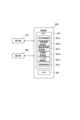
図1に示すように、本実施形態の画像形成装置100は、制御手段としての制御部300を有している。制御部300について、図3を用いて説明する。図3に示すように、制御部300は、CPU301(Central Processing Unit)、ROM(Read Only Memory)やRAM(Random Access Memory)などのメモリ302を有する。メモリ302には、例えば印刷プログラム(後述する図8参照)や画像形成ジョブなどの各種プログラム、後述する封筒情報や載置部情報あるいは制御テーブル(後述する表1参照)などの各種データが記憶され得る。CPU301は、メモリ302に記憶されている各種プログラムを実行可能である。なお、メモリ302は、各種プログラムの実行に伴う演算処理結果などを一時的に記憶することもできる。
<Control part>
As shown in FIG. 1, the
本実施形態の場合、CPU301は印刷プログラムを実行することにより、封筒Sなどの記録材への印刷に関する画像形成装置100の動作を制御し得る。なお、印刷プログラムはソフトウェアプログラムの形態に限られず、例えばDSP(ディジタル・シグナル・プロセッサ)によって処理されるマイクロプログラムの形態などでも実施可能である。即ち、CPU301は画像形成ジョブなどの制御プログラムを実行して画像形成動作などの各種制御を行うものを併用してよいが、これに限らず、印刷プログラムを実行するのに専用に用意されたものを用いてもよい。
In the case of this embodiment, the
このCPU301に対し、通信バス等(例えばデータ及びアドレスバス)を介して、操作部400や表示部410が接続されている。操作部400は、ユーザによる画像形成ジョブなどの各種プログラムの実行開始操作や各種データ入力操作などを受け付ける、例えば操作パネルや外部端末などである。操作部400は、後述するように(図4参照)、ユーザ入力を受け付ける操作キーや操作ボタンなどの各種操作子を有する。表示部410は、後述するような、印刷する封筒Sに関する各種データを入力するための入力画面(図5参照)などの各種画面を適宜に表示し得る。本実施形態の場合、表示部410は種々の仮想操作子が表示され、ユーザによる仮想操作子へのタッチ操作に応じて各種データの入力などを受け付ける、所謂タッチパネル方式のディスプレイである。なお、表示部410は装置本体100aに備え付けられたものに限らず、例えば装置本体100aに接続された外部ディスプレイ、あるいはパーソナルコンピュータなどの外部端末のディスプレイなどであってよい。また、表示部410は、画像形成装置100と相互に通信可能であれば、有線で接続されてもよいし無線で接続されてもよい。
An
<操作部>
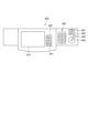
図4に、操作部400の一例を示す。図4に示すように、操作部400には、プリンターキー401、コピーモードキー402、テンキー403、リセットキー404、ストップキー405、スタートキー406、パワー(オンオフ)スイッチ407などの各種操作子が設けられている。プリンターキー401は、通常印刷に関する各種データの入力を行うために用いられる。コピーモードキー402は、画像形成装置100を複写機(コピーモード)として使用する場合に、コピー印刷に関する各種データの入力を行うために用いられる。プリンターキー401やコピーモードキー402が操作された場合、例えば表示部410に各種データの入力を行うための入力画面が表示される。テンキー403は、例えば印刷枚数などの数値に関する情報を入力するために用いられる。リセットキー404は、各キーの操作により入力された各種データを初期値にリセットするために用いられる。ストップキー405は、例えば実行中の画像形成ジョブを強制的に停止させるために用いられる。スタートキー406は、コピーモード時の原稿画像の読み取り動作を含め、画像形成ジョブの開始を指示するために用いられる。パワースイッチ407は、画像形成装置100の電源をオン/オフするために用いられる。
<Operation unit>
FIG. 4 shows an example of the
<入力画面>
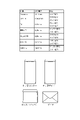
図5に、表示部410に表示する入力画面の一例を示す。ただし、図5では画像形成装置100を複写機(コピーモード)として用いた場合を例に示した。コピーモードであることを示すため、図5に示す入力画面には「コピーできます」と表示される。この入力画面には仮想操作子として、用紙選択キー411、坪量選択キー412、サイズ選択キー413、印刷モードキー414、封筒印刷面選択キー415、設定解除キー416、OKキー417が表示されている。ユーザは表示部410に表示されたこれら仮想操作子を用いて、印刷に関する各種データを選択的に入力可能である。即ち、表示部410は表示手段として機能するだけでなく、画面に仮想操作子が表示されることによって入力手段としても機能し得る。上記の仮想操作子は、ユーザに操作されるたびに反転表示される。これにより、ユーザは操作した仮想操作子に対応づけられた表示内容に関する情報の選択を行ったことを知ることができる。なお、図5に示した仮想操作子は一例であり、上記したものに限られない。
<Input screen>
FIG. 5 shows an example of an input screen displayed on the
用紙選択キー411は、印刷する記録材を選択するために、カセット12、手差しトレイ11、載置装置20のうちのいずれかを入力するのに用いられる。用紙選択キー411により入力されたカセット12、手差しトレイ11、載置装置20(以下、これらを載置部とも呼ぶ)のうちのいずれかが載置部情報としてメモリ302(図3参照)に記憶される。ここでは、手差しトレイ11に封筒Sを載置して印刷するために、「手差しトレイ 封筒」が選択されている場合を示した。
A
坪量選択キー412は、封筒Sの坪量を入力するのに用いられる。サイズ選択キー413は、用紙選択キー411により入力された載置部に載置する封筒Sのサイズ(種類)を入力するのに用いられる。ここでは、手差しトレイ11に載置する封筒Sのサイズとして「モナーク(Monarch)、長形3号、洋長形3号、角形2号、不定形」のいずれかを入力できるようにしている。封筒Sのサイズとして不定形が入力された場合には、ユーザがテンキー403(図4参照)などを用いて任意のサイズを入力する。こうして選択あるいは入力された封筒Sのサイズ(種類)は、封筒情報としてメモリ302に記憶される。本実施形態の場合、封筒情報には画像形成を行う封筒Sの種類の他に、封筒Sの坪量に関する情報を有し得る。
A
印刷モードキー414は、記録材の片面のみに印刷する片面印刷モードと、記録材の両面に印刷する両面印刷モードのいずれかを入力するのに用いられる。ユーザは、原稿の両面を記録材の片面にあるいは原稿の片面を記録材の片面に印刷する片面印刷モード、原稿の片面を記録材の両面にあるいは原稿の両面を記録材の両面に印刷する両面印刷モードを選択できる。封筒印刷面選択キー415は、ユーザが封筒Sの宛名面(フラップの形成されている面)を印刷するか、封筒Sの非宛名面(フラップの形成されていない面)を印刷するかを選択するのに用いられる。なお、封筒Sの両面印刷を行う場合には、封筒印刷面選択キー415により選択された面が先に印刷されてもよいし、あるいは封筒印刷面選択キー415を表示せず、予め封筒Sの宛名面又は非宛名面のいずれかが先に印刷されるようになっていてもよい。設定解除キー416は、上記した各キーの操作により入力された情報を解除するのに用いられる。OKキー417は、上記した各キーの操作により入力された情報を確定するのに用いられる。
A
図3の説明に戻り、CPU301は、操作部400や表示部410により入力された各種データを取得して、メモリ302に記憶する。CPU301は、例えばユーザによる画像形成装置100の電源オン等の起動操作に応じて、印刷プログラム(図8参照)をメモリ302から読み出して実行する。制御部300は、印刷プログラムの実行により、表示制御部301a、封筒情報取得部301b、載置部情報取得部301c、印刷面取得部301d、ニップ圧制御部301e、温度制御部301fとして機能する。
Returning to the description of FIG. 3 , the
表示制御部301aは、表示部410の表示を制御する。表示制御部301aは表示部410の表示制御として、上記した入力画面を表示する他に、カセット12、手差しトレイ11、載置装置20への封筒Sの載置方法を表示部410に表示する。封筒情報取得部301bは、例えば操作部400や表示部410で入力された封筒Sのサイズなどの封筒情報を取得し、メモリ302に記憶する。載置部情報取得部301cは、表示部410で入力された封筒Sが載置されるカセット12、手差しトレイ11、載置装置20の載置部情報を取得し、メモリ302に記憶する。
The
印刷面取得部301dは、上述した封筒印刷面選択キー415の操作に応じて選択される封筒Sの印刷面に関する情報(宛名面か非宛名面か)を取得し、メモリ302に記憶する。ニップ圧制御部301eは、後述するように(図8参照)、取得した封筒Sの印刷面に関する情報に基づいて加圧モータ700の回転方向と回転量を変化させることにより加圧調整機構800を制御し、定着ニップUのニップ圧を調整し得る。温度制御部301fは、温度センサ210(図2参照)の検出結果を参照して、後述するように、定着ベルト130の表面温度を封筒Sの坪量に関する情報に応じた所定温度に設定するために、誘導加熱装置150を制御する。
The print
ところで、従来では、既に述べたように、封筒Sにトナー像を定着させる際に宛名面と非宛名面とで同じニップ圧により定着が行われていた。それ故、封筒Sの宛名面の定着に伴って封筒に段差跡(封筒しわ)が生じるか、封筒Sの非宛名面の定着に伴ってトナー像の定着不良が生じるかする虞があった。これは、封筒Sが袋状に形成され、紙と紙とが貼り合わされている箇所(貼り合わせ部と呼ぶ)とそれ以外の箇所とで厚みが異なる故に、定着ニップUにおいてそれらの箇所で実際にかかる圧力が異なり得るからである。 By the way, conventionally, as described above, when the toner image is fixed on the envelope S, the same nip pressure is applied to the address side and the non-address side. Therefore, there is a risk that a stepped mark (envelope wrinkle) may occur on the envelope when the address surface of the envelope S is fixed, or a fixing failure of the toner image may occur when the non-address surface of the envelope S is fixed. This is because the envelope S is formed in a bag-like shape, and the thickness differs between the portion where the paper sheets are bonded together (referred to as a bonded portion) and the other portions. This is because the pressures applied to
即ち、封筒Sは筒状に折り返した紙と紙の一部を貼り合わせて作成され、規格サイズだけでも様々な種類が存在する。図6に、代表的な封筒の種類、短辺長さ(幅方向長さ)、貼り合わせ形状を示した。図6に示すように、日本や海外で流通している代表的な封筒Sとして、短辺長さが98mmから240mmまでの封筒Sが存在する。また、封筒Sは同じ種類であってもその折り方は多様である。例えば和封筒の場合には、幅方向中央に紙の一部が貼り合わされた貼り合わせ部を有する「センター貼り」や、幅方向の片側端部に貼り合わせ部を有する「サイド貼り」などがある。洋封筒の場合には、幅方向の両側端部に貼り合わせ部を有する「カマス貼り」や、フラップが三角形であって斜めの形状の貼り合わせ部を有する「ダイヤモンド貼り」などがある。 In other words, the envelope S is made by pasting a sheet of paper folded back into a cylindrical shape and a part of the paper, and there are various types of standard sizes alone. FIG. 6 shows the types of typical envelopes, the short side length (the length in the width direction), and the pasted shape. As shown in FIG. 6, representative envelopes S distributed in Japan and overseas include envelopes S with a short side length of 98 mm to 240 mm. In addition, even if the envelopes S are of the same type, the folding methods are diverse. For example, in the case of Japanese envelopes, there are "center pasting" where a part of the paper is pasted together in the center of the width direction, and "side pasting" where there is a pasting part at one end in the width direction. . In the case of Western-style envelopes, there are "barracuda-pasted", which has glued portions on both sides in the width direction, and "diamond-pasted", which has a triangular flap and oblique-shaped glued portions.
これら多種多様な封筒Sにトナー像を定着させる場合、普通紙よりも低い封筒専用のニップ圧を用いることで、宛名面の定着時に生じやすい封筒しわを抑制するようにしている。しかし、そうした場合、従来では非宛名面の定着時に定着不良が生じていた。これは、定着ニップUにおいて封筒Sの形状や坪量によって貼り合わせ部にかかる実際の圧力が不足する、所謂圧抜けが生じ得るからである。非宛名面定着時の圧抜けについて、図7(a)及び図7(b)を用いてサイド貼りの封筒Sを例にして説明する。 When a toner image is fixed on these various types of envelopes S, the nip pressure for envelopes, which is lower than that for plain paper, is used to suppress wrinkling of the envelope, which tends to occur during fixing of the address surface. However, in such a case, conventionally, fixing failure occurred when the non-address side was fixed. This is because the shape and basis weight of the envelope S at the fixing nip U may cause a so-called pressure drop in which the actual pressure applied to the bonded portion is insufficient. The pressure release during fixing of the non-address side will be described with reference to FIGS.
図7(a)に示すように、封筒Sの搬送方向に交差する方向(幅方向)端部に貼り合わせ部HA1がある封筒S、例えば長形3号のサイド貼りのような紙の3枚重ねと2枚重ねの境界部分RY(図中、斜線部)で定着不良が発生しやすいことが分かっている。図7(b)に示すように、この境界部分には紙一枚分の段差が生じており、この部分に定着ベルト130(図2参照)が倣うことができず、部分的に圧力が不足して定着性が低下することが要因の1つである。また、加圧ローラ121がクラウン形状であることも要因の1つとして挙げられる。即ち、クラウン形状の場合、定着ニップUにおいて加圧ローラ121の長手方向中央部の圧力よりも両端部側の圧力が低下しやすい傾向にある。端部側の圧力がより不足しやすいことで、封筒Sの境界部分RYで定着不良が生じ得る。
As shown in FIG. 7(a), three sheets of envelope S, for example,
そこで、この点に鑑み、本実施形態では、定着ニップUを通過する際に封筒Sの厚みが異なる箇所で実際にかかる圧力がトナー像の定着に最適な圧力となるように、封筒Sの宛名面定着時と非宛名面定着時とでニップ圧を異ならせている。以下、説明する。 In view of this point, in the present embodiment, the address of the envelope S is adjusted so that the pressure actually applied to portions of the envelope S having different thicknesses when passing through the fixing nip U is optimal for fixing the toner image. Different nip pressures are applied when the surface is fixed and when the non-address surface is fixed. This will be explained below.
<印刷処理>
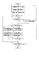
本実施形態の印刷処理について、図3乃至図5を参照しながら図8を用いて説明する。ここに示す印刷処理は制御部300により、例えば操作部400のプリンターキー401あるいはコピーモードキー402が操作された場合に開始され、操作部400のスタートキー406が操作された場合つまりは画像形成ジョブの開始に応じて終了される。
<Print processing>
The print processing of this embodiment will be described using FIG. 8 while referring to FIGS. 3 to 5. FIG. The print processing shown here is started by the
制御部300は、表示部410に上述した入力画面(図5参照)等を表示し、表示した入力画面を通じてユーザ入力を受け付ける(S1)。このユーザ入力に応じて、制御部300では、封筒情報取得部301bが封筒Sの種類や坪量に関する情報を有する封筒情報を取得し得る(S2)。また、載置部情報取得部301cが載置部情報を取得し得る。さらに、制御部300では、印刷面取得部301dが封筒Sの印刷面に関する情報(印刷面が宛名面であるか非宛名面であるか)を取得する(S3)。そして、制御部300は、印刷する記録材が封筒Sであるか否かを判定する(S4)。印刷する記録材が封筒Sでない場合(S4のNO)、制御部300はステップS13の処理へジャンプする。他方、印刷する記録材が封筒Sである場合(S4のYES)、制御部300は印刷する封筒Sが定形封筒であるか否かを判定する(S5)。封筒Sが定形封筒でない場合(S5のNO)、制御部300は操作部400のテンキー403の操作により入力された封筒Sのサイズ(サイズ入力情報)を取得する(S6)。取得したサイズ入力情報は、封筒情報の一部データとしてメモリ302に記憶される。
The
制御部300は、取得した封筒Sの印刷面に関する情報に基づき、宛名面の印刷を行うか非宛名面の印刷を行うかを判定する(S7)。宛名面の印刷を行う場合(S7のYES)、制御部300では、ニップ圧制御部301eが封筒Sの印刷面に関する情報に基づいて宛名面定着時のニップ圧を設定する(S8)。また、表示制御部301aが封筒画像を含む「宛名面印刷時の載置方法」(後述の図9(a)参照)を表示部410に表示する(S9)。他方、非宛名面の印刷を行う場合(S7のNO)、制御部300では、ニップ圧制御部301eが封筒Sの印刷面に関する情報に基づいて非宛名面定着時のニップ圧を設定する(S10)。また、表示制御部301aが封筒画像を含む「非宛名面印刷時の載置方法」(後述の図9(b)参照)を表示部410に表示する(S11)。
The
<封筒の載置方法の表示例>
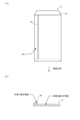
ここで、表示部410に表示される「宛名面印刷時の載置方法」と「非宛名面印刷時の載置方法」とについて、図9(a)及び図9(b)を用いて説明する。ここでは、短辺側にフラップSaがある封筒S(例えば角形2号)を手差しトレイ11に載置する場合を例に、「宛名面印刷時の載置方法」の表示例を図9(a)に、「非宛名面印刷時の載置方法」の表示例を図9(b)に示した。本実施形態の場合、表示部410には封筒Sの載置方法を、文字で説明する文字情報と、封筒SのフラップSaの向きと封筒Sの表裏とを含む封筒画像で示す画像情報とにより表示される。なお、長辺側にフラップSaがある封筒S(例えば洋長形3号)の場合も同様の表示であってよい。また、長辺側にフラップSaがある封筒Sの場合、フラップSa(ふた)が封筒Sの搬送方向に交差する方向に沿うように封筒Sを載置させる表示であってもよい。
<Display example of how to place envelopes>
Here, "placement method for address side printing" and "placement method for non-address side printing" displayed on the
図9(a)に示すように、手差しトレイ11に載置される封筒Sの宛名面の印刷が選択されている場合には、封筒Sの宛名面(フラップSaの形成されている面)が上面側を向くように、封筒Sの載置方法が表示される。他方、図9(b)に示すように、手差しトレイ11に載置される封筒Sの非宛名面の印刷が選択されている場合には、封筒Sの非宛名面(フラップSaの形成されていない面)が上面側を向くように、封筒Sの載置方法が表示される。なお、ここでは、フラップSaのない閉じられた短辺側(非フラップ側)を搬送方向先端側に向けるように表示した例を示したが、非フラップ側を搬送方向後端側に向けるように表示してもよい。
As shown in FIG. 9A, when printing on the address side of the envelope S placed on the
なお、載置装置20に載置される封筒Sの宛名面の印刷が選択されている場合は、図9(a)に示した「宛名面印刷時の載置方法」と同じ表示、即ち封筒Sの宛名面が上面側を向いた載置方法が表示される。また、載置装置20に載置される封筒Sの非宛名面の印刷が選択されている場合は、図9(b)に示した「非宛名面印刷時の載置方法」と同じ表示、即ち封筒Sの非宛名面が上面側を向いた載置方法が表示される。これに対し、カセット12に載置される封筒Sの宛名面の印刷が選択されている場合は、封筒Sの非宛名面が上面側を向いた載置方法つまり図9(b)に示した載置方法が表示される。ただし、文字情報は「宛名面を上にして封筒をセットしてください」と表示される。また、カセット12に載置される封筒Sの非宛名面の印刷が選択されている場合は、封筒Sの宛名面が上面側を向いた載置方法つまり図9(a)に示した載置方法が表示される。ただし、文字情報は「非宛名面を上にして封筒をセットしてください」と表示される。これは、上述したように、手差しトレイ11や載置装置20の封筒Sは表裏が載置状態のまま二次転写部T2に搬送されるが、カセット12の封筒Sは表裏が載置状態と逆になって二次転写部T2に搬送されるからである。こうした載置部によって異なり得る載置方法の表示は、載置部情報取得部301cにより取得される載置部情報に基づき行われる。
When printing of the address side of the envelope S placed on the
また、フラップSaが搬送方向に交差する方向に沿うように載置方法を表示する場合は、図9(a)や図9(b)に示したように、フラップSaのある短辺側(フラップ側)を搬送方向後端として表示部410に表示すると、封筒しわを防止できるので好ましい。
When the placement method is displayed so that the flap Sa is along the direction intersecting the transport direction, as shown in FIGS. side) is displayed on the
図8の説明に戻り、制御部300では、ニップ圧制御部301eが設定したニップ圧に調整すべく、加圧モータ700を制御する(S12)。そして、制御部300は、スタートキー406のユーザ操作により画像形成ジョブの開始が指示されたか否かを判定する(S13)。画像形成ジョブの開始が指示されていない場合(S13のNO)、制御部300は、上記したS1~S12の処理を繰り返す。画像形成ジョブの開始が指示されている場合(S13のYES)、制御部300は本印刷処理を終了する。
Returning to the description of FIG. 8, the
制御部300(詳しくはニップ圧制御部301e)では、表1に示す制御テーブル(データ)に従って定着ニップUのニップ圧を設定する。ただし、表1では定着ニップUのニップ圧を、加圧モータ700の基準位置からの回転量(pls)により示している。表1から理解できるように、宛名面定着時に必要なニップ圧を確保するには、加圧モータ700の回転量を200~600(pls)の範囲で変化させる必要がある。他方、非宛名面定着時に必要なニップ圧を確保するには、加圧モータ700の回転量を400~800(pls)の範囲で変化させる必要がある。本実施形態の場合、封筒の宛名面の定着時にニップ圧を第一ニップ圧に調整し、封筒の非宛名面の定着時にニップ圧を第一ニップ圧よりも大きい第二ニップ圧に調整する。一例として、宛名面定着時のニップ圧は100(N)以上500(N)以下、好ましくは150(N)以上450(N)以下であり、非宛名面定着時のニップ圧は250(N)以上650(N)以下、好ましくは300(N)以上600(N)以下である。また、非宛名面定着時に必要なニップ圧の方が、宛名面定着時に必要なニップ圧よりも大きくなるように、加圧モータ700の回転量が設定されている。例えば、ニップ圧は圧抜けする分の圧力を考慮して宛名面や非宛名面でのトナー像の定着に最適な値に設定されるのが好ましい。なお、表1に示す制御テーブル(データ)は封筒Sの種類毎にメモリ302に記憶されていてもよい。その場合、制御部300は封筒情報に従って該当する制御テーブルを参照し得る。

なお、封筒Sを形成する原紙や坪量は多様であり、原紙の種類としては例えばクラフト、ケント、上質紙、コットンペーパーなどがある。そして、同じクラフトでもその坪量は50gsm~120gsmと幅広い坪量を有している。そこで、本実施形態の場合、表1に示すように、制御テーブルには、宛名面定着時のニップ圧と非宛名面定着時のニップ圧とが封筒Sの坪量に応じて異なるように、加圧モータ700の回転量が設定されている。これは、封筒Sの坪量が大きくなると、封筒Sの厚み分だけ定着ニップUで実際にかかる圧力が高くなり得るからである。本実施形態では、封筒Sの坪量が第一坪量の場合における宛名面定着時のニップ圧(第一ニップ圧)と非宛名面定着時のニップ圧(第二ニップ圧)とを、第一坪量よりも大きい第二坪量のときのそれぞれのニップ圧よりも大きくしている。つまり、封筒Sの坪量が小さくなるにつれて、坪量が大きい場合に比較して、宛名面定着時のニップ圧(第一ニップ圧)と非宛名面定着時のニップ圧(第二ニップ圧)が共に大きくなるように、加圧モータ700の回転量が設定されている。
Note that there are various base papers and basis weights for forming the envelope S, and examples of types of base paper include kraft paper, Kent paper, high-quality paper, and cotton paper. The same kraft has a wide range of basis weights, from 50 gsm to 120 gsm. Therefore, in the case of the present embodiment, as shown in Table 1, the control table is configured so that the nip pressure when fixing the address side and the nip pressure when fixing the non-address side differ according to the basis weight of the envelope S. The amount of rotation of the
また、制御テーブルには、表1に示すように、定着ベルト130の表面温度が封筒Sの坪量毎に設定されている。これは、封筒Sの坪量が大きくなると、封筒Sの厚み分だけ定着ニップUでトナー像を定着するのに必要な熱量が増加するからである。そこで、本実施形態では、封筒Sの坪量が第一坪量の場合に表面温度が第一温度になるように、封筒Sの坪量が第一坪量よりも大きい第二坪量の場合に表面温度が第一温度よりも高い第二温度になるように、定着ベルト130の表面温度が設定されている。制御部300は制御テーブルに従って、誘導加熱装置150を制御して定着ベルト130の表面温度を設定温度に調節し得る。
In the control table, the surface temperature of the fixing
上述したように、本実施形態では、制御テーブルを参照して封筒Sの宛名面定着時と非宛名面定着時とでニップ圧を異ならせるようにした。宛名面定着時と非宛名面定着時とでニップ圧を異ならせた場合に、定着ニップUで封筒Sにかかる圧力について、長形3号のサイド貼り封筒Sを例に図10(a)及び図10(b)を用いて説明する。図10(a)は宛名面定着時に定着ニップUで封筒Sにかかる圧力を示し、図10(b)は非宛名面定着時に定着ニップUで封筒Sにかかる圧力を示す。 As described above, in this embodiment, the control table is referred to and the nip pressure is made different between when the address side of the envelope S is fixed and when the non-address side is fixed. Fig. 10(a) and Fig. 10(a) show the pressure applied to the envelope S at the fixing nip U when different nip pressures are applied when the address side is fixed and when the non-address side is fixed. Description will be made with reference to FIG. FIG. 10(a) shows the pressure applied to the envelope S at the fixing nip U when the address side is fixed, and FIG. 10(b) shows the pressure applied to the envelope S at the fixing nip U when the non-address side is fixed.
図10(a)及び図10(b)の横軸は定着ベルト130の長手幅(長手方向長さ)を示し、縦軸は封筒Sにかかる圧力を示している。長手幅の中で、封筒Sが狭持されている部分を封筒幅とし、封筒Sの形状による圧力分布を示している。なお、図中において、宛名面にかかる圧力を「P1」、境界部分RY(図7(a)参照)にかかる圧力を「P2」、貼り合わせ部HA1(図7(a)参照)にかかる圧力を「P3」、定着に必要な最低限の圧力を「P4」で示した。
10A and 10B, the horizontal axis indicates the longitudinal width (longitudinal length) of the fixing
図10(a)に示すように、宛名面定着時に封筒Sが定着ニップUを通過する際に、貼り合わせ部HA1にかかる圧力P3が大きくなる。一方で、境界部分RYでは紙一枚分の段差で圧抜けが生じるため、境界部分RYにかかる圧力P2は低下する。そして、印字面である宛名面にかかる圧力P1は、段差がなく均一なため圧力P2よりも大きな圧力がかかる。封筒Sの宛名面定着時にはこうした圧力分布が生じるが故に、境界部分RYにかかる圧力P2が定着に必要な圧力P4よりも小さくなることがあり、その場合、境界部分RYで圧抜けが生じて定着不良を生じさせ得る。そこで、本実施形態ではこれに対応するために、宛名面定着時に境界部分RYにかかる圧力P2が定着に必要な圧力P4よりも大きくなるように、ニップ圧が設定される。ただし、ニップ圧が大き過ぎると、貼り合わせ部HA1への圧力が高くなりすぎて封筒Sに段差跡を生じさせる可能性が高くなる。そこで、本実施形態においては封筒Sへのダメージを考慮して、境界部分RYにかかる圧力P2がほぼ定着に必要な圧力P4となるニップ圧に設定されるのが望ましい。 As shown in FIG. 10A, when the envelope S passes through the fixing nip U during fixing of the address surface, the pressure P3 applied to the bonding portion HA1 increases. On the other hand, at the boundary portion RY, a step corresponding to one sheet of paper causes a pressure release, so the pressure P2 applied to the boundary portion RY decreases. Since the pressure P1 applied to the address side, which is the printing surface, is uniform without steps, the pressure is greater than the pressure P2. Since such a pressure distribution occurs when the address surface of the envelope S is fixed, the pressure P2 applied to the boundary portion RY may become smaller than the pressure P4 required for fixing. can cause defects. Therefore, in this embodiment, in order to deal with this, the nip pressure is set so that the pressure P2 applied to the boundary portion RY during fixing of the address surface is greater than the pressure P4 required for fixing. However, if the nip pressure is too high, the pressure on the bonding portion HA1 is too high, and the envelope S is more likely to be marked with a step. Therefore, in this embodiment, in consideration of damage to the envelope S, it is desirable to set the pressure P2 applied to the boundary portion RY to a nip pressure that is approximately equal to the pressure P4 required for fixing.
他方、図10(b)に示すように、封筒Sの非宛名面定着時に宛名面定着時と同じニップ圧に設定した場合、段差が大きい境界部分RYで生じる圧抜けによって、境界部分RYにかかる圧力P2が定着に必要な圧力P4を下回る虞がある(図中破線)。即ち、同じ封筒Sでも非宛名面の定着時に、境界部分RYにかかる圧力P2が定着に必要な圧力P4に満たない場合がある。そうであれば、境界部分RYで定着不良が生じ得る。そこで、非宛名面定着時には、ニップ圧を宛名面定着時よりも高くしてトナー像の定着性を確保する必要がある。本実施形態の場合、非宛名面定着時のニップ圧を宛名面定着時のニップ圧よりも高くに設定することから、図10(b)に示すように、圧抜けが生じる境界部分RYを含む長手幅の全域に亘って、封筒Sにかかる圧力が定着に必要な圧力P4を上回る。そうなるように、非宛名面定着時のニップ圧が設定される。ただし、この場合も封筒Sへのダメージを考慮して、境界部分RYにかかる圧力P2がほぼ定着に必要な圧力P4となるニップ圧に設定されるのが望ましい。 On the other hand, as shown in FIG. 10(b), when the same nip pressure is set when fixing the non-address side of the envelope S as when fixing the address side, the boundary portion RY is affected by pressure relief occurring at the boundary portion RY where the step is large. There is a risk that the pressure P2 will fall below the pressure P4 required for fixing (broken line in the figure). That is, even with the same envelope S, when the non-address side is fixed, the pressure P2 applied to the boundary portion RY may be less than the pressure P4 required for fixing. If so, fixing failure may occur at the boundary portion RY. Therefore, when fixing the non-address surface, it is necessary to make the nip pressure higher than that when fixing the address surface to ensure fixability of the toner image. In the case of this embodiment, since the nip pressure when fixing the non-address side is set higher than the nip pressure when fixing the address side, as shown in FIG. Over the entire longitudinal width, the pressure applied to the envelope S exceeds the pressure P4 required for fixing. The nip pressure at the time of fixing the non-address side is set so as to do so. However, in this case as well, considering damage to the envelope S, it is desirable that the pressure P2 applied to the boundary portion RY is set to a nip pressure that is approximately equal to the pressure P4 required for fixing.
以上のように、本実施形態では、封筒Sが定着ニップUを通過する際に生じる圧抜けを考慮して、封筒の宛名面定着時と封筒の非宛名面定着時とでニップ圧を異ならせてトナー像の定着を行うことができるようにした。上述したように、非宛名面定着時のニップ圧(第二ニップ圧)が宛名面定着時のニップ圧(第一ニップ圧)よりも大きくなるようにしている。こうすると、宛名面定着時と非宛名面定着時とに関わらず、境界部分RYにかかる圧力P2(図10(a)、図10(b)参照)を定着に必要な圧力P4よりも大きくできる。それ故、圧抜けが生じる境界部分RYを含む封筒Sの長手幅の全域に亘って、封筒Sにかかる圧力が定着に必要な圧力P4を上回ることになる。これにより、宛名面定着時と非宛名面定着時とに関わらず、封筒S固有の厚みの違いによる圧力差に起因する封筒しわや定着不良を抑制でき、もって封筒Sの宛名面と非宛名面との定着を適切に行い得る。 As described above, in the present embodiment, taking into consideration the pressure release that occurs when the envelope S passes through the fixing nip U, the nip pressure is set differently when fixing the address side of the envelope and when fixing the non-address side of the envelope. The toner image can be fixed by pressing the As described above, the nip pressure (second nip pressure) during fixing of the non-address surface is set to be higher than the nip pressure (first nip pressure) during fixing of the address surface. By doing so, the pressure P2 (see FIGS. 10A and 10B) applied to the boundary portion RY can be made larger than the pressure P4 required for fixing regardless of whether the address side is fixed or the non-address side is fixed. . Therefore, the pressure applied to the envelope S exceeds the pressure P4 required for fixing over the entire longitudinal width of the envelope S including the boundary portion RY where pressure loss occurs. As a result, regardless of whether the address surface is fixed or the non-address surface is fixed, wrinkles and fixing failure due to the pressure difference due to the difference in thickness inherent to the envelope S can be suppressed. and can be properly fixed.
<他の実施形態>
なお、上述した実施形態では、各色の感光ドラム1Y~1Kから中間転写ベルト8に各色のトナー像を一次転写した後に、封筒Sに各色の複合トナー像を一括して二次転写する構成の画像形成装置を説明したが、これに限らない。例えば、感光ドラム1Y~1Kから封筒Sに直接転写する直接転写方式の画像形成装置であってもよい。
<Other embodiments>
In the above-described embodiment, after the toner images of each color are primarily transferred from the photosensitive drums 1Y to 1K of each color to the
11…第一載置部(手差しトレイ)、12…第二載置部(カセット)、20…第一載置部(載置装置)、120…ニップ形成部材(加圧ベルト)、130…定着部材(定着ベルト)、200…定着装置、210…検出手段(サーミスタ)、300…制御手段(制御部)、410…表示部(入力手段)、800…加圧調整機構、PY~PK…画像形成部、S…封筒、U…定着ニップ
DESCRIPTION OF
Claims (7)
封筒にトナー像を形成可能な画像形成部と、
定着部材と、前記定着部材を加熱する加熱部と、前記定着部材に当接して前記封筒が挟持搬送される定着ニップを形成する加圧部材を有し、熱及び圧により前記封筒にトナー像を定着させる定着装置と、
前記定着部材と前記加圧部材間の圧力を調整可能な加圧調整機構と、
前記封筒の前記第二面に画像を形成する指示が入力された場合には、前記加圧調整機構の圧力を第一の圧力に調整し、前記封筒の前記第一面に画像を形成する指示が入力された場合には、前記加圧調整機構の圧力を前記第一の圧力よりも大きい第二の圧力に調整することにより、トナー像が前記封筒に定着するように前記加圧調整機構を制御する制御部と、を備える、
ことを特徴とする画像形成装置。 a first side of the envelope including a seam, which is an area where the paper is stuck together, and a second side of the envelope, opposite the first side, that does not include the seam and has a flap. In an image forming apparatus capable of forming an image on a surface,
an image forming unit capable of forming a toner image on an envelope;
A fixing member, a heating section for heating the fixing member, and a pressing member for forming a fixing nip in which the envelope is nipped and conveyed while being in contact with the fixing member. a fixing device for fixing;
a pressure adjustment mechanism capable of adjusting pressure between the fixing member and the pressure member;
When an instruction to form an image on the second side of the envelope is input, an instruction to adjust the pressure of the pressure adjustment mechanism to a first pressure and form an image on the first side of the envelope is input, by adjusting the pressure of the pressure adjustment mechanism to a second pressure higher than the first pressure, the pressure adjustment mechanism is operated so that the toner image is fixed on the envelope. A control unit that controls
An image forming apparatus characterized by:
前記制御部は、前記封筒の坪量が第一坪量の場合における前記第一の圧力と前記第二の圧力とを、前記第一坪量よりも大きい第二坪量の場合における前記第一の圧力と前記第二の圧力よりも大きくするように前記加圧調整機構を制御する、
ことを特徴とする請求項1に記載の画像形成装置。 an acquisition unit that acquires information about the basis weight of the envelope;
The control unit adjusts the first pressure and the second pressure when the grammage of the envelope is the first grammage to the first pressure when the grammage is the second grammage larger than the first grammage. controlling the pressurization adjustment mechanism to be greater than the pressure of and the second pressure ;
2. The image forming apparatus according to claim 1, wherein:
封筒の坪量に関する情報を取得する取得部と、
前記温度検出部の検出結果に基づいて、前記封筒の表面温度が目標温度となるように前記加熱部の通電を制御する通電制御部と、を備え、
前記通電制御部は、前記封筒の坪量が第一坪量の場合に前記目標温度を第一温度に設定し、封筒の坪量が前記第一坪量よりも大きい第二坪量の場合に前記目標温度を前記第一温度よりも高い第二温度に設定する、
ことを特徴とする請求項1又は2に記載の画像形成装置。 a temperature detection unit that detects the surface temperature of the fixing member;
an acquisition unit that acquires information about the basis weight of the envelope;
an energization control unit that controls energization of the heating unit so that the surface temperature of the envelope reaches a target temperature based on the detection result of the temperature detection unit;
The energization control unit sets the target temperature to the first temperature when the grammage of the envelope is the first grammage, and sets the target temperature to the first temperature when the grammage of the envelope is the second grammage larger than the first grammage. setting the target temperature to a second temperature higher than the first temperature;
3. The image forming apparatus according to claim 1, wherein:
前記封筒の下面側にトナー像を形成する搬送路へ搬送されるように前記封筒を載置する第二載置部と、
前記第一載置部と前記第二載置部とを選択可能な選択部と、
表示部と、
画像を形成する封筒の面を特定する情報を入力する入力装置と、を備え、
前記制御部は、前記入力装置により入力された情報に基づいて、前記第一載置部又は前記第二載置部に載置する封筒の載置方法を前記表示部に表示する、
ことを特徴とする請求項1乃至3のいずれか1項に記載の画像形成装置。 a first placement unit on which the envelope is placed so as to be transported to a transport path for forming a toner image on the upper surface of the envelope;
a second placement unit for placing the envelope so as to be transported to a transport path for forming a toner image on the lower surface of the envelope;
a selection unit capable of selecting between the first placement unit and the second placement unit;
a display unit;
an input device for inputting information identifying the side of the envelope on which the image is to be formed ;
The control unit displays , on the display unit, a method of placing an envelope to be placed on the first placement unit or the second placement unit based on information input by the input device .
4. The image forming apparatus according to claim 1, wherein:
前記第二載置部は、カセットである、The second placement section is a cassette,
ことを特徴とする請求項4に記載の画像形成装置。5. The image forming apparatus according to claim 4, wherein:
前記定着部材は、磁束により生じる渦電流によって発熱する導電層を有する、The fixing member has a conductive layer that generates heat by eddy currents generated by magnetic flux.
ことを特徴とする請求項1乃至5のいずれか1項に記載の画像形成装置。6. The image forming apparatus according to claim 1, wherein:
ことを特徴とする請求項1乃至6のいずれか1項に記載の画像形成装置。7. The image forming apparatus according to claim 1, wherein:
Priority Applications (2)
| Application Number | Priority Date | Filing Date | Title |
|---|---|---|---|
| JP2018217145A JP7224870B2 (en) | 2018-11-20 | 2018-11-20 | image forming device |
| US16/688,176 US10877414B2 (en) | 2018-11-20 | 2019-11-19 | Image forming apparatus with a fixing device controlled for envelope printing |
Applications Claiming Priority (1)
| Application Number | Priority Date | Filing Date | Title |
|---|---|---|---|
| JP2018217145A JP7224870B2 (en) | 2018-11-20 | 2018-11-20 | image forming device |
Publications (3)
| Publication Number | Publication Date |
|---|---|
| JP2020086021A JP2020086021A (en) | 2020-06-04 |
| JP2020086021A5 JP2020086021A5 (en) | 2021-12-23 |
| JP7224870B2 true JP7224870B2 (en) | 2023-02-20 |
Family
ID=70726568
Family Applications (1)
| Application Number | Title | Priority Date | Filing Date |
|---|---|---|---|
| JP2018217145A Active JP7224870B2 (en) | 2018-11-20 | 2018-11-20 | image forming device |
Country Status (2)
| Country | Link |
|---|---|
| US (1) | US10877414B2 (en) |
| JP (1) | JP7224870B2 (en) |
Families Citing this family (4)
| Publication number | Priority date | Publication date | Assignee | Title |
|---|---|---|---|---|
| US11269272B2 (en) | 2019-11-12 | 2022-03-08 | Canon Kabushiki Kaisha | Fixing device including an endless belt for fixing a toner image on a recording material |
| JP2021096401A (en) | 2019-12-18 | 2021-06-24 | キヤノン株式会社 | Fixing device |
| JP2021096402A (en) | 2019-12-18 | 2021-06-24 | キヤノン株式会社 | Fixing device |
| JP7388300B2 (en) | 2020-06-26 | 2023-11-29 | コニカミノルタ株式会社 | Image forming device, control method and program |
Citations (1)
| Publication number | Priority date | Publication date | Assignee | Title |
|---|---|---|---|---|
| JP2017116704A (en) | 2015-12-24 | 2017-06-29 | キヤノン株式会社 | Fixing device |
Family Cites Families (14)
| Publication number | Priority date | Publication date | Assignee | Title |
|---|---|---|---|---|
| JPS61294477A (en) * | 1985-06-24 | 1986-12-25 | Ricoh Co Ltd | Electrostatic recording device |
| JPH04358189A (en) * | 1991-06-04 | 1992-12-11 | Canon Inc | Image forming device |
| JP4181494B2 (en) * | 2003-12-26 | 2008-11-12 | 株式会社沖データ | Fixing apparatus and image forming apparatus |
| JP2007183480A (en) * | 2006-01-10 | 2007-07-19 | Funai Electric Co Ltd | Image forming apparatus |
| JP4830581B2 (en) | 2006-03-30 | 2011-12-07 | ブラザー工業株式会社 | Image forming apparatus capable of changing nip pressure of fixing unit based on paper width |
| JP5898477B2 (en) * | 2011-12-01 | 2016-04-06 | キヤノン株式会社 | Printing apparatus, control method therefor, and program |
| JP6237717B2 (en) * | 2015-06-26 | 2017-11-29 | コニカミノルタ株式会社 | Fixing apparatus and image forming apparatus |
| JP2017090549A (en) * | 2015-11-04 | 2017-05-25 | キヤノンファインテック株式会社 | Image formation device, and control method for the same |
| CN108475034B (en) * | 2015-12-25 | 2021-04-13 | 佳能株式会社 | Fixing device and image forming apparatus |
| JP2017156475A (en) * | 2016-02-29 | 2017-09-07 | キヤノン株式会社 | Image formation device, and fixation device |
| JP6827720B2 (en) * | 2016-06-17 | 2021-02-10 | キヤノン株式会社 | Image forming device |
| JP6881904B2 (en) * | 2016-07-13 | 2021-06-02 | キヤノン株式会社 | Image forming device |
| JP6963470B2 (en) * | 2017-11-07 | 2021-11-10 | キヤノン株式会社 | Image forming device |
| JP7158939B2 (en) * | 2018-07-27 | 2022-10-24 | キヤノン株式会社 | Image forming apparatus and image forming system |
-
2018
- 2018-11-20 JP JP2018217145A patent/JP7224870B2/en active Active
-
2019
- 2019-11-19 US US16/688,176 patent/US10877414B2/en active Active
Patent Citations (1)
| Publication number | Priority date | Publication date | Assignee | Title |
|---|---|---|---|---|
| JP2017116704A (en) | 2015-12-24 | 2017-06-29 | キヤノン株式会社 | Fixing device |
Also Published As
| Publication number | Publication date |
|---|---|
| US20200159153A1 (en) | 2020-05-21 |
| US10877414B2 (en) | 2020-12-29 |
| JP2020086021A (en) | 2020-06-04 |
Similar Documents
| Publication | Publication Date | Title |
|---|---|---|
| JP7224870B2 (en) | image forming device | |
| JP6573366B2 (en) | Image forming apparatus and image forming system | |
| JP6541396B2 (en) | Control device and image forming apparatus | |
| JP7224849B2 (en) | image forming device | |
| JP2017062514A (en) | Image forming apparatus | |
| JP2016006488A (en) | Fixing unit and image forming apparatus | |
| US10578999B2 (en) | Image forming apparatus and image forming system | |
| JP2008221477A (en) | Image forming apparatus | |
| US10809948B2 (en) | Preview screen display apparatus, preview screen display method, and preview screen display program | |
| JP7171363B2 (en) | image forming device | |
| AU2019451355A1 (en) | Fixing device and image-forming apparatus | |
| JP5451523B2 (en) | Image forming apparatus | |
| JP5641818B2 (en) | Image forming system and image forming apparatus | |
| JP2022073597A (en) | Image forming system, and program | |
| JP6123543B2 (en) | Image forming apparatus, abnormality detection apparatus, and abnormality detection program | |
| JP5821763B2 (en) | Image forming apparatus, image forming apparatus control method, and image forming apparatus control program | |
| JP2010002670A (en) | Image forming device | |
| JP2020075426A (en) | Control device and program | |
| JP6685718B2 (en) | Fixing device | |
| JP2005164730A (en) | Image forming apparatus | |
| EP3640738A1 (en) | Image forming apparatus and control method of image forming apparatus | |
| JP6771953B2 (en) | Image forming device | |
| JP2021135418A (en) | Image forming apparatus | |
| JP4019836B2 (en) | Sheet transport system | |
| JP5887781B2 (en) | Driving device and image forming apparatus |
Legal Events
| Date | Code | Title | Description |
|---|---|---|---|
| RD02 | Notification of acceptance of power of attorney |
Free format text: JAPANESE INTERMEDIATE CODE: A7422 Effective date: 20200206 |
|
| RD04 | Notification of resignation of power of attorney |
Free format text: JAPANESE INTERMEDIATE CODE: A7424 Effective date: 20200207 |
|
| A521 | Request for written amendment filed |
Free format text: JAPANESE INTERMEDIATE CODE: A523 Effective date: 20211111 |
|
| A621 | Written request for application examination |
Free format text: JAPANESE INTERMEDIATE CODE: A621 Effective date: 20211111 |
|
| A977 | Report on retrieval |
Free format text: JAPANESE INTERMEDIATE CODE: A971007 Effective date: 20220930 |
|
| A131 | Notification of reasons for refusal |
Free format text: JAPANESE INTERMEDIATE CODE: A131 Effective date: 20221004 |
|
| A521 | Request for written amendment filed |
Free format text: JAPANESE INTERMEDIATE CODE: A523 Effective date: 20221125 |
|
| TRDD | Decision of grant or rejection written | ||
| A01 | Written decision to grant a patent or to grant a registration (utility model) |
Free format text: JAPANESE INTERMEDIATE CODE: A01 Effective date: 20230110 |
|
| A61 | First payment of annual fees (during grant procedure) |
Free format text: JAPANESE INTERMEDIATE CODE: A61 Effective date: 20230208 |
|
| R151 | Written notification of patent or utility model registration |
Ref document number: 7224870 Country of ref document: JP Free format text: JAPANESE INTERMEDIATE CODE: R151 |