EP1548437A1 - VERFAHREN ZUR ANORDNUNG VON FL SSIGEN REAKTIONSKOMPONENTEN AUF EINER SUBSTRATOBERFLûCHE ZUR ERKENNUNG EINER ZIELSUBSTANZ DURCH REAKTION MEHRERER KOMPONENTEN AUF DEM SUBSTRAT, VORRICHTUNG DAF R UND ARTIKEL ZUR VERWENDUNG BEI DEM VERFAHREN - Google Patents
VERFAHREN ZUR ANORDNUNG VON FL SSIGEN REAKTIONSKOMPONENTEN AUF EINER SUBSTRATOBERFLûCHE ZUR ERKENNUNG EINER ZIELSUBSTANZ DURCH REAKTION MEHRERER KOMPONENTEN AUF DEM SUBSTRAT, VORRICHTUNG DAF R UND ARTIKEL ZUR VERWENDUNG BEI DEM VERFAHREN Download PDFInfo
- Publication number
- EP1548437A1 EP1548437A1 EP03797637A EP03797637A EP1548437A1 EP 1548437 A1 EP1548437 A1 EP 1548437A1 EP 03797637 A EP03797637 A EP 03797637A EP 03797637 A EP03797637 A EP 03797637A EP 1548437 A1 EP1548437 A1 EP 1548437A1
- Authority
- EP
- European Patent Office
- Prior art keywords
- component
- reaction
- substrate
- components
- supply means
- Prior art date
- Legal status (The legal status is an assumption and is not a legal conclusion. Google has not performed a legal analysis and makes no representation as to the accuracy of the status listed.)
- Withdrawn
Links
Images


Classifications
-
- B—PERFORMING OPERATIONS; TRANSPORTING
- B01—PHYSICAL OR CHEMICAL PROCESSES OR APPARATUS IN GENERAL
- B01L—CHEMICAL OR PHYSICAL LABORATORY APPARATUS FOR GENERAL USE
- B01L3/00—Containers or dishes for laboratory use, e.g. laboratory glassware; Droppers
- B01L3/02—Burettes; Pipettes
- B01L3/0241—Drop counters; Drop formers
-
- C—CHEMISTRY; METALLURGY
- C12—BIOCHEMISTRY; BEER; SPIRITS; WINE; VINEGAR; MICROBIOLOGY; ENZYMOLOGY; MUTATION OR GENETIC ENGINEERING
- C12M—APPARATUS FOR ENZYMOLOGY OR MICROBIOLOGY; APPARATUS FOR CULTURING MICROORGANISMS FOR PRODUCING BIOMASS, FOR GROWING CELLS OR FOR OBTAINING FERMENTATION OR METABOLIC PRODUCTS, i.e. BIOREACTORS OR FERMENTERS
- C12M1/00—Apparatus for enzymology or microbiology
- C12M1/34—Measuring or testing with condition measuring or sensing means, e.g. colony counters
-
- B—PERFORMING OPERATIONS; TRANSPORTING
- B01—PHYSICAL OR CHEMICAL PROCESSES OR APPARATUS IN GENERAL
- B01L—CHEMICAL OR PHYSICAL LABORATORY APPARATUS FOR GENERAL USE
- B01L3/00—Containers or dishes for laboratory use, e.g. laboratory glassware; Droppers
- B01L3/02—Burettes; Pipettes
- B01L3/0241—Drop counters; Drop formers
- B01L3/0262—Drop counters; Drop formers using touch-off at substrate or container
-
- C—CHEMISTRY; METALLURGY
- C12—BIOCHEMISTRY; BEER; SPIRITS; WINE; VINEGAR; MICROBIOLOGY; ENZYMOLOGY; MUTATION OR GENETIC ENGINEERING
- C12Q—MEASURING OR TESTING PROCESSES INVOLVING ENZYMES, NUCLEIC ACIDS OR MICROORGANISMS; COMPOSITIONS OR TEST PAPERS THEREFOR; PROCESSES OF PREPARING SUCH COMPOSITIONS; CONDITION-RESPONSIVE CONTROL IN MICROBIOLOGICAL OR ENZYMOLOGICAL PROCESSES
- C12Q1/00—Measuring or testing processes involving enzymes, nucleic acids or microorganisms; Compositions therefor; Processes of preparing such compositions
- C12Q1/68—Measuring or testing processes involving enzymes, nucleic acids or microorganisms; Compositions therefor; Processes of preparing such compositions involving nucleic acids
-
- G—PHYSICS
- G01—MEASURING; TESTING
- G01N—INVESTIGATING OR ANALYSING MATERIALS BY DETERMINING THEIR CHEMICAL OR PHYSICAL PROPERTIES
- G01N21/00—Investigating or analysing materials by the use of optical means, i.e. using sub-millimetre waves, infrared, visible or ultraviolet light
- G01N21/62—Systems in which the material investigated is excited whereby it emits light or causes a change in wavelength of the incident light
- G01N21/63—Systems in which the material investigated is excited whereby it emits light or causes a change in wavelength of the incident light optically excited
- G01N21/64—Fluorescence; Phosphorescence
- G01N21/6428—Measuring fluorescence of fluorescent products of reactions or of fluorochrome labelled reactive substances, e.g. measuring quenching effects, using measuring "optrodes"
-
- G—PHYSICS
- G01—MEASURING; TESTING
- G01N—INVESTIGATING OR ANALYSING MATERIALS BY DETERMINING THEIR CHEMICAL OR PHYSICAL PROPERTIES
- G01N21/00—Investigating or analysing materials by the use of optical means, i.e. using sub-millimetre waves, infrared, visible or ultraviolet light
- G01N21/62—Systems in which the material investigated is excited whereby it emits light or causes a change in wavelength of the incident light
- G01N21/63—Systems in which the material investigated is excited whereby it emits light or causes a change in wavelength of the incident light optically excited
- G01N21/64—Fluorescence; Phosphorescence
- G01N21/645—Specially adapted constructive features of fluorimeters
- G01N21/6452—Individual samples arranged in a regular 2D-array, e.g. multiwell plates
-
- G—PHYSICS
- G01—MEASURING; TESTING
- G01N—INVESTIGATING OR ANALYSING MATERIALS BY DETERMINING THEIR CHEMICAL OR PHYSICAL PROPERTIES
- G01N33/00—Investigating or analysing materials by specific methods not covered by groups G01N1/00 - G01N31/00
- G01N33/48—Biological material, e.g. blood, urine; Haemocytometers
- G01N33/50—Chemical analysis of biological material, e.g. blood, urine; Testing involving biospecific ligand binding methods; Immunological testing
- G01N33/53—Immunoassay; Biospecific binding assay; Materials therefor
-
- B—PERFORMING OPERATIONS; TRANSPORTING
- B01—PHYSICAL OR CHEMICAL PROCESSES OR APPARATUS IN GENERAL
- B01F—MIXING, e.g. DISSOLVING, EMULSIFYING OR DISPERSING
- B01F33/00—Other mixers; Mixing plants; Combinations of mixers
- B01F33/30—Micromixers
- B01F33/302—Micromixers the materials to be mixed flowing in the form of droplets
- B01F33/3021—Micromixers the materials to be mixed flowing in the form of droplets the components to be mixed being combined in a single independent droplet, e.g. these droplets being divided by a non-miscible fluid or consisting of independent droplets
-
- B—PERFORMING OPERATIONS; TRANSPORTING
- B01—PHYSICAL OR CHEMICAL PROCESSES OR APPARATUS IN GENERAL
- B01J—CHEMICAL OR PHYSICAL PROCESSES, e.g. CATALYSIS OR COLLOID CHEMISTRY; THEIR RELEVANT APPARATUS
- B01J2219/00—Chemical, physical or physico-chemical processes in general; Their relevant apparatus
- B01J2219/00274—Sequential or parallel reactions; Apparatus and devices for combinatorial chemistry or for making arrays; Chemical library technology
- B01J2219/00277—Apparatus
- B01J2219/00279—Features relating to reactor vessels
- B01J2219/00306—Reactor vessels in a multiple arrangement
- B01J2219/00313—Reactor vessels in a multiple arrangement the reactor vessels being formed by arrays of wells in blocks
- B01J2219/00315—Microtiter plates
- B01J2219/00317—Microwell devices, i.e. having large numbers of wells
-
- B—PERFORMING OPERATIONS; TRANSPORTING
- B01—PHYSICAL OR CHEMICAL PROCESSES OR APPARATUS IN GENERAL
- B01J—CHEMICAL OR PHYSICAL PROCESSES, e.g. CATALYSIS OR COLLOID CHEMISTRY; THEIR RELEVANT APPARATUS
- B01J2219/00—Chemical, physical or physico-chemical processes in general; Their relevant apparatus
- B01J2219/00274—Sequential or parallel reactions; Apparatus and devices for combinatorial chemistry or for making arrays; Chemical library technology
- B01J2219/00277—Apparatus
- B01J2219/00351—Means for dispensing and evacuation of reagents
- B01J2219/00378—Piezoelectric or ink jet dispensers
-
- B—PERFORMING OPERATIONS; TRANSPORTING
- B01—PHYSICAL OR CHEMICAL PROCESSES OR APPARATUS IN GENERAL
- B01J—CHEMICAL OR PHYSICAL PROCESSES, e.g. CATALYSIS OR COLLOID CHEMISTRY; THEIR RELEVANT APPARATUS
- B01J2219/00—Chemical, physical or physico-chemical processes in general; Their relevant apparatus
- B01J2219/00274—Sequential or parallel reactions; Apparatus and devices for combinatorial chemistry or for making arrays; Chemical library technology
- B01J2219/00277—Apparatus
- B01J2219/00351—Means for dispensing and evacuation of reagents
- B01J2219/00387—Applications using probes
-
- B—PERFORMING OPERATIONS; TRANSPORTING
- B01—PHYSICAL OR CHEMICAL PROCESSES OR APPARATUS IN GENERAL
- B01J—CHEMICAL OR PHYSICAL PROCESSES, e.g. CATALYSIS OR COLLOID CHEMISTRY; THEIR RELEVANT APPARATUS
- B01J2219/00—Chemical, physical or physico-chemical processes in general; Their relevant apparatus
- B01J2219/00274—Sequential or parallel reactions; Apparatus and devices for combinatorial chemistry or for making arrays; Chemical library technology
- B01J2219/00277—Apparatus
- B01J2219/00497—Features relating to the solid phase supports
- B01J2219/00527—Sheets
-
- B—PERFORMING OPERATIONS; TRANSPORTING
- B01—PHYSICAL OR CHEMICAL PROCESSES OR APPARATUS IN GENERAL
- B01J—CHEMICAL OR PHYSICAL PROCESSES, e.g. CATALYSIS OR COLLOID CHEMISTRY; THEIR RELEVANT APPARATUS
- B01J2219/00—Chemical, physical or physico-chemical processes in general; Their relevant apparatus
- B01J2219/00274—Sequential or parallel reactions; Apparatus and devices for combinatorial chemistry or for making arrays; Chemical library technology
- B01J2219/00718—Type of compounds synthesised
- B01J2219/0072—Organic compounds
-
- B—PERFORMING OPERATIONS; TRANSPORTING
- B01—PHYSICAL OR CHEMICAL PROCESSES OR APPARATUS IN GENERAL
- B01L—CHEMICAL OR PHYSICAL LABORATORY APPARATUS FOR GENERAL USE
- B01L3/00—Containers or dishes for laboratory use, e.g. laboratory glassware; Droppers
- B01L3/50—Containers for the purpose of retaining a material to be analysed, e.g. test tubes
- B01L3/508—Containers for the purpose of retaining a material to be analysed, e.g. test tubes rigid containers not provided for above
- B01L3/5085—Containers for the purpose of retaining a material to be analysed, e.g. test tubes rigid containers not provided for above for multiple samples, e.g. microtitration plates
- B01L3/50853—Containers for the purpose of retaining a material to be analysed, e.g. test tubes rigid containers not provided for above for multiple samples, e.g. microtitration plates with covers or lids
-
- B—PERFORMING OPERATIONS; TRANSPORTING
- B01—PHYSICAL OR CHEMICAL PROCESSES OR APPARATUS IN GENERAL
- B01L—CHEMICAL OR PHYSICAL LABORATORY APPARATUS FOR GENERAL USE
- B01L3/00—Containers or dishes for laboratory use, e.g. laboratory glassware; Droppers
- B01L3/50—Containers for the purpose of retaining a material to be analysed, e.g. test tubes
- B01L3/508—Containers for the purpose of retaining a material to be analysed, e.g. test tubes rigid containers not provided for above
- B01L3/5088—Containers for the purpose of retaining a material to be analysed, e.g. test tubes rigid containers not provided for above confining liquids at a location by surface tension, e.g. virtual wells on plates, wires
-
- C—CHEMISTRY; METALLURGY
- C40—COMBINATORIAL TECHNOLOGY
- C40B—COMBINATORIAL CHEMISTRY; LIBRARIES, e.g. CHEMICAL LIBRARIES
- C40B60/00—Apparatus specially adapted for use in combinatorial chemistry or with libraries
- C40B60/14—Apparatus specially adapted for use in combinatorial chemistry or with libraries for creating libraries
-
- G—PHYSICS
- G01—MEASURING; TESTING
- G01N—INVESTIGATING OR ANALYSING MATERIALS BY DETERMINING THEIR CHEMICAL OR PHYSICAL PROPERTIES
- G01N35/00—Automatic analysis not limited to methods or materials provided for in any single one of groups G01N1/00 - G01N33/00; Handling materials therefor
- G01N35/00029—Automatic analysis not limited to methods or materials provided for in any single one of groups G01N1/00 - G01N33/00; Handling materials therefor provided with flat sample substrates, e.g. slides
- G01N2035/00099—Characterised by type of test elements
- G01N2035/00158—Elements containing microarrays, i.e. "biochip"
-
- G—PHYSICS
- G01—MEASURING; TESTING
- G01N—INVESTIGATING OR ANALYSING MATERIALS BY DETERMINING THEIR CHEMICAL OR PHYSICAL PROPERTIES
- G01N35/00—Automatic analysis not limited to methods or materials provided for in any single one of groups G01N1/00 - G01N33/00; Handling materials therefor
- G01N35/10—Devices for transferring samples or any liquids to, in, or from, the analysis apparatus, e.g. suction devices, injection devices
- G01N2035/1027—General features of the devices
- G01N2035/1034—Transferring microquantities of liquid
- G01N2035/1039—Micropipettes, e.g. microcapillary tubes
Definitions
- the present invention relates to the detection of a target substance in a large number of isolated reaction reactions on a substrate surface by utilizing a specific coupling reaction as in the assay method using micro-array. More particularly, the present invention relates to a method of dispensing the liquid components required for the specific coupling reaction onto the substrate surface. The present invention also relates to an apparatus for dispensing the liquid components on the substrate surface. Further, the present invention relates to an article useful for performing the method noted above.
- the living body is controlled by the expression of various physiologically active substances present in the living body texture.
- a micro-array is used nowadays as the main means of the gene expression frequency analysis that controls the expression of the physiologically active substances.
- the micro-array is prepared by arranging and immobilizing probes such as DNA, RNA and proteins on a substrate such as a slide glass or a silicon substrate in a density of thousands of probes per square centimeter.
- a micro-array prepared by immobilizing nucleic acid probes on a solid phase substrate is used as a means for analyzing the expression frequency of the target DNA and target RNA, because the immobilized probes are specifically coupled with target DNA or RNA by the hybridization reaction.
- the three technologies of photolithography (light immobilization), ink jetting and mechanical micro-spotting are mainly used for preparing the micro-array, in order to spotting trace amount of probes on the substrate surface.
- the hybridization reaction between the trace amount of probes immobilized on the substrate surface and a target contained in a sample solution is carried out in general as follows. Specifically, the micro-array having the probes immobilized thereon is covered with, for example, a cover glass and, then, a target solution is injected into the clearance between the cover glass and the micro-array so as to carry out the hybridization reaction between the probes and the target contained in the sample solution.
- the cover glass noted above serves to prevent the evaporation of the sample solution.
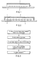
- a lid member such as a cover glass 3 is arranged so as to face probes 2 such as trace amount of DNA immobilized on a micro-array substrate 1 such as a slide glass, and the clearance between the cover glass 3 and the probes 2 is filled with a sample solution 4 containing a target, thereby forming a hybrid between the probe and the target.
- the background noise noted above refers to the phenomenon that signals are detected in regions to which the probes have not been immobilized, depending on the amount of the fluorescent substance used as a marker and the composition of the solution used in the step of the hybridization. If the background noise is high, the detection sensitivity of the actual hybridization signal is lowered.
- a first object of the present invention which has been achieved in view of the situation described above, is to provide a method of detecting one of two components collectively forming a specific coupling pair consisting of a probe and a target, the component providing the probe being spotted and immobilized into solid phase on a substrate surface, and the other component being detected as the target, and is intended to improve the efficiency of the specific coupling reaction between the two components, to lower the background noise and to decrease the amount of the sample solution used. Further, the present invention is intended to realize a reaction having a high reliability in the detecting method described above.
- a second object of the present invention is to provide an apparatus for working the detecting method described above.
- a third object of the present invention is to provide an article useful for the detecting method described above.
- a solution containing a target substance is regioselectively disposed on the prove region in which trace amount of probe is immobilized on, for example, a micro-array substrate by using, for example, a spotting device.
- the first object of the present invention is achieved by providing a method of carrying out a specific coupling reaction between first and second components collectively forming a specific coupling pair, which method comprises:
- the second object of the present invention is achieved by providing an apparatus for detecting a target substance within a large number of isolated reaction regions on a substrate surface by using at least two kinds of the reacting components, the apparatus comprising:
- the third object of the present invention is achieved by providing an article that is prepared to perform the detecting reaction of a target substance within a plurality of isolated reaction regions on a substrate surface by using first and second components collectively forming a specific coupling pair and at least one kind of a third reaction component; wherein at least two of the first, second and third reaction components, which are lacking at least one reaction components required for the detecting reaction, are regioselectively superposed one upon the other within the reaction region under the state that these components can be stored.
- substrate in the present invention denotes a solid phase member having a plurality of isolated regions in which a biological material such as a nucleic acid, protein or a cell can be arranged and immobilized on the same plane.
- the surface of the substrate is sufficient for forming a plurality of two-dimensional or three-dimensional regions in which the biological material can be arranged.
- a micro-array comprising a platelike substrate such as a slide glass, a plastic plate, a silicon wafer or a porous filter and a biological material that is regioselectively arranged in a plurality of isolated regions on the surface of the substrate.
- the micro-array typically includes a substrate in which the portion for arranging the biological material has a two-dimensional plane.
- the substrate it is also possible for the substrate to include a three-dimensional recess or a hollow portion (see Japanese Patent Announcement (Kohyo) No. 9-504864).
- a one-dimensional micro-array i.e., a linear micro-array, is also known to the art (see WO 01/051207).
- first and second components collectively forming a specific coupling pair.
- the pair of components represents, for example, a combination of a probe substance and a target substance.
- the combinations of the first and second components used in the present invention include, but not limited to, a combination of a nucleic acid such as a gene and a complementary strand thereof, a combination of an antigen and an antibody, a combination of an allergen and an antibody, and a combination of an enzyme and a substrate.
- a detectable label such as a fluorescent dye, a chemical luminescent substance, a magnetic substance or a gold colloid to be coupled with one or both of these first and second components.
- biological materials can be used in the form of a liquid phase or a solid phase as far as the volume of the biological material is small enough to be arranged in a plurality of relatively small isolated regions on the substrate surface.
- a protein cell that is a membrane component, such as an antigen, an allergen or a receptor is used as the first component or the second component
- the protein which is extracted by lysis treatment of the cell, in the form of a liquid phase or a solid phase. It is also possible to use the cell itself as it is.
- There is a known protein array in which the extracted protein is arranged in a plurality of isolated regions on the substrate surface see WO 00/04382).
- nucleic acid is used as the first component or the second component, it is possible to use any of DNA, RNA or a modified nucleic acid such as PNA as the nucleic acid.
- These nucleic acids are designed to have a desired length, base sequence and conformation (single chain, double chain, cyclic, linear), and be used in the form of a liquid phase or a solid phase having the nucleic acid content adjusted at an appropriate level.
- the first or second component can be in the form of a solid phase reagent such as beads, which has been immobilized with the first or second component by coating the beads with a liquid phase biological material or by wetting the beads with the liquid phase biological material.
- the third component used in the present invention includes, for example, a component promoting or initiating the specific coupling reaction between the first component and the second component, a nucleic acid primer, DNA polymerase, ligase, exonuclease, and a multivalent antibody (secondary antibody).
- the third component includes, for example, a ligand, an inhibitor or a membrane protein digesting agent (protease), which are common to the first component and the second component.
- reaction region in the present invention denotes the region on the substrate in which a specific coupling reaction is carried out between the first component and the second component. It is possible for the reaction region to be a region defined in advance by forming, for example, a recessed section. However, the reaction region need not be such a predefined region. In this case, the reaction region is defined by the first component arranged in advance.
- the staying region of the target solution can be limited to a region in the vicinity of the probe by regioselectively supplying a solution containing the second component (e.g., a target substance) onto the first component (e.g., a probe) in a superposing fashion, i.e., in a manner to cover the first component.
- the target solution since it is possible for the target solution to obtain a spatial thickness, the diffusion effect of the target solution can be expected so as to increase the specific coupling efficiency of the target substance that is supplied in a superposing fashion onto the probe.
- the presence of the target solution in any region other than the region in which the probe is arranged in advance is eliminated, with the result that the back ground noise coming from other than the reaction region is considered to be eliminated.
- the target solution is regioselectively supplied onto the probe in a superposing fashion, i.e., in a manner to cover the probe, by using the technology of ink jetting or mechanical spotting and, thus, only several nanoliters (nL) of the target solution is required for a single spot, i.e., single reaction region.
- nL nanoliters
- the target solution can be saved so as to achieve cost reduction.
- the present invention it is particularly effective in the present invention to supply regioselectively a sample onto the region in which the probe is immobilized to a solid phase in a superposing fashion, i.e., in a manner to cover the particular reaction region noted above. It is also possible to supply onto the particular region in a superposing fashion various reagents required for the analysis in place of the sample. It follows that the technical scope of the present invention also covers the case where various reagents are supplied in a covering fashion onto the region in which the probe is immobilized to a solid phase.
- FIGS. 2 and 3 we will describe in the following, the detecting method according to a first embodiment of the present invention in which a nucleic acid such as gene is detected by using a micro-array in which a nucleic acid probe is immobilized.
- FIG. 2 illustrates the detecting method of the first embodiment
- FIG. 3 is a flowchart showing the steps for carrying out the method of the first embodiment.
- a trace amount of a solution 7 containing a target is supplied in a superposing fashion onto a trace amount of a probe 6 such as DNA immobilized on a micro-array substrate 5.
- a spotting device such as a pin-type device or an ink jet arrayer is used for supplying the solution 7.
- the micro-array substrate 5 having the probe immobilized thereon is mounted on a spotting device such as an ink jet arrayer.
- a slide glass having a position-aligning index-mark put on, for example, an edge of the substrate having the probe immobilized thereon in order to permit the solution 7 containing the target to be supplied onto the immobilized probe 6 in a superposing fashion, i.e., in a manner to cover the immobilized probe 6.
- the target solution 7 is supplied onto the immobilized probe 6 in a manner to superpose thereon so as to permit the target to be spotted on the immobilized probe 6.
- the probes and the target-containing solution that are arranged spot-like are covered with a lid member 8.
- a trace amount of probes such as DNA which are immobilized on the micro-array substrate, form a hybrid with the target labeled with the fluorescent molecule within the target-containing solution.
- the expression frequency of the target gene can be measured by measuring the amount of fluorescent light emitted from the target hybridized with the probe which has been immobilized on the micro-array in advance.
- the technology of ink jetting and mechanical micro-spotting which was used in prior arts for immobilizing the probe, can also be applied to the hybridization test.
- the target is supplied in a superposing fashion onto a trace amount of the probe immobilized on the micro-array substrate so as to permit the target to be positioned closer to the probe, leading to an improved efficiency of the hybridization. Also, since the hybridization solution does not permeate into a region other than the probe, the background noise is lowered so as to facilitate the analysis.
- each constituent element of the first embodiment can be variously modified or changed naturally.
- a slide glass is used as the substrate.
- substrates of various materials such as a silicon wafer, as well as various shapes and sizes.
- a fluorescent dye is often contained in the target solution, it is desirable to use, for example, the substrate made of a glass that does not emit fluorescent light. This is because such the substrate enables to decrease the background noise from the substrate in analyzing the micro-array.
- the isolated reaction regions on the substrate are slightly recessed in order to permit the target to be positioned closer to the probe when a target solution is supplied onto the reaction regions having the probe immobilized thereon in a superposing fashion, i.e., in a manner to cover the probe.
- the cover substrate has a capillary structure so as to permit the cover substrate to be partitioned for each spot.
- the probe and the target used are substances having an electric charge such as DNA
- an electric charge is applied from the lower portion of the substrate.
- the probe and the target are attracted toward the substrate so as to carry out the hybridization effectively.
- the present invention is also directed to an apparatus for carrying out the method of the present invention described above.
- An apparatus according to one embodiment of the present invention will now be described with reference to FIGS. 8 and 9.
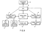
- FIG. 8 is a block diagram showing the construction of the gist portion of the apparatus of the present invention.
- the apparatus of the present invention comprises an address detecting means 11, a central processing unit (CPU) 12, an address storing section 13, a dispensing control section 14, a reagent (second component) dispenser 15, a measuring section 16, an output display section 19, a reading means 18, and a sample dispenser 17. Signals are transmitted between these members of the apparatus as denoted by arrows in the drawing.
- the apparatus also comprises a holding means (not shown) for holding a substrate 20 having a plurality of isolated reaction regions 21 formed on the surface as shown in FIG. 9.
- the reaction regions 21 are arranged to form a matrix array on the surface of the substrate 20.
- the address of each reaction region 21 is designated by the combination (x n , y n ) of the position on the X-axis and the position on the Y-axis, the X- and Y-axes collectively forming a coordinate.
- a first component 22 required for carrying out a prescribed reaction is arranged in advance on each reaction region 21, and a second component 23 denoted by a black dot is arranged on the first component 22.
- the second component 23 is shown in only some of the reaction regions 21 in FIG. 9.
- first component 22 and the second component 23 in all the reaction regions 21. It is also possible for the kinds of first component 22 arranged in these large number of reaction regions 21 to be equal to or to differ from each other. Likewise, it is possible for the kinds of second component 23 arranged in these large number of reaction regions 21 to be equal to or to differ from each other. It is also possible to arrange, for example, the same kind of first component in the reaction regions forming the same row or the same column. Likewise, it is possible to arrange the same kind of first and second component in the reaction regions forming the same row or the same column. Further, it is possible to arrange a different kind of first and second component in the reaction regions forming a different row or a different column.
- the address detecting device 11 included in the apparatus of the present invention serves to detect the address of each reaction region 21 (the address of the first component 22) on the surface of the substrate 20 held by the holding means described above.
- the detected address is stored in the address storing section 13.
- the central processing unit (CPU) 12 transmits an instruction to the dispensing control section 14 in accordance with the address information so as to control the reagent dispenser 15 for arranging the second component.
- the second component is regioselectively dispensed onto the first component 22 in a superposing fashion, i.e., in a manner to cover the first component.
- the first component supply means 17 for arranging the first component is also included in the apparatus so as to make it possible to carry out the operation starting with the arrangement of the first component 22 by using the substrate 20 not having the first component arranged thereon in advance.
- the first component supply means 17 is also controlled by the dispensing control section 14.
- the first component and the second component as well as an appropriate third component, as required, are arranged one upon the other in a superposed fashion.
- the CPU 12 transmits an electrical signal to the measuring control section 16 so as to detect the result of the prescribed detecting reaction via the detecting means 11.
- the detecting means 11 detects a detectable label such as a fluorescent marker in respect of each reaction region 21, and the result of the detection is transmitted to the CPU 12.
- the detected signal is subjected to arithmetic processing in the CPU 12, and the CPU 12 permits the result of the arithmetic processing to be displayed on the appropriate output display section 19 such as a CRT monitor.
- the principle of the address detection by the detecting device 11 is to recognize the difference in the characteristics in terms of materials science between the substrate 20 and the first component 22 arranged in the reaction region 21 on the substrate 20.
- the address detecting device 11 it is desirable for the address detecting device 11 to be a physical means, preferably to have an optical measuring function or another measuring function that can be associated with the optical measuring data.
- the sites where the first component is present and is not present are detected on the basis of the difference in the transmittance and/or the reflectance of wave energy (light or ultrasonic wave) so as to recognize the presence of the first component 22.
- the recognition signal is subjected to arithmetic processing in the CPU 12 so as to determine the address of the first component 22 (i.e., the address of the reaction region 21) on the substrate surface. It follows that it is desirable for the address detecting device 11 to further include means for converting the detection signal given from the substrate 20 into an electrical signal adapted for the arithmetic processing carried out by the CPU 12.
- the detection data obtained from the address detecting device 11 is adapted for forming an image of the arrangement layout of the substrate 20 and all the sites of the first component 22 on the substrate 20.
- the difference in the light transmittance is detected by a light beam, provided are a shadow image or a color image of the substrate 20 and the first component 22.
- the detection is performed on the basis of the difference in light reflectance
- a light-reflective material e.g., silicon oxide
- a surface plasmon resonance method or a polarization measuring means such as an eripsometer.
- the first component contains a light scattering polymer or a metal colloid
- the distribution image of the first component 22 on the substrate 20 reflects accurately not only the individual address of the first component 22 but also the two-dimensional or three-dimensional volume of the first component 22.
- the address detecting means includes the reading means 18 for reading the two-dimensional or three-dimensional shape and/or size of the first component 22 on the basis of the lengths on the x-, y- and z-axes of the first component 22.
- the reading means 18 determines the center of the first component 22 as the address information. It follows that, in dispensing the succeeding second component, it is possible to dispense the second component toward the center noted above.
- a liquid material containing the second component 23 can be regioselectively supplied onto the first component 22 arranged in advance on the substrate 20 in a manner to cover the first component 22, as shown in FIG. 10A.
- the first component 22a is a sample such as a cell
- the second component 23 is a reagent such as an antigen.
- the first component 22 is a reagent such as a DNA probe
- the second component 23 is a sample containing DNA such as a gene.
- the first component 22 is sized relatively large entity such as a cell, it is possible to select a specified portion of the first component 22 so as to determine the center of the specified portion.
- an imaging means such as a CCD camera or a laser scanning device in order to detect a shadow image of light or a color image for forming an image. If the beam diameter of the light beam in the laser scanning device is made slightly larger than the volume of the first component, it is possible to increase the imaging speed. On the other hand, if the beam diameter is made smaller than the volume of the first component, it is possible to obtain the detailed information within the volume of the first component.
- the cell used as the first component 22 contains in general many kinds of valuable reaction factors on the surface or inside thereof, it is advantageous to obtain detailed information from the first component 22. It follows that, where the detecting means includes a confocal optical system, it is possible to know not only the layout of the first component 22 on the substrate 20 but also the optical characteristics for every specified portion within the first component 22. In the case of arranging the every second component that carries out a specific reaction for every specified portion of the first component, it suffices to arrange the every second component in a manner to cover selectively the specified portion of the first component. Also, in the case of applying a reagent like protease that permits dissolving only partially the cell membrane, it suffices to arrange the second component in a manner to cover the dissolved portion alone on the upper surface of the cell used as the first component 22.
- the address detecting means 11 can be similarly utilized in the subsequent step of obtaining the result of the biological reaction carried out for the first component in each address after addition of all the required components including the second component.
- the address detecting means 11 is indispensable in the case where the first component is arranged in advance on the substrate 20. In other words, it is not absolutely necessary to obtain the address information by the address detecting means 11 in the case where the operation is started with the arrangement of the first component, i.e., the case where the first component and the second component are arranged simultaneously or sequentially. It should be noted in this connection that, in the particular case noted above, it is possible to obtain an effective address information from the dispensing control section 14 for controlling the movement of the dispenser apparatus in the directions of the x-, y- and z-axes, said dispenser apparatus acting as an arranging means for arranging the first component. It follows that it is not absolutely necessary to obtain the address information by the address detecting means 11 in the case where the operation is started with the arrangement of the first component, as pointed out above.
- the address storing section 13 may be formed of any memory means such as a random access memory (RAM) capable of storing the address information of the first component 22 transmitted from the address detecting means 11 or from the reading means 18 and also capable of reading the stored information as required.
- RAM random access memory
- the second component supply means 15 is formed of a dispenser equipped with a spurting nozzle for regioselectively arranging a liquid material containing the second component in a superposing fashion on the first component 22 arranged in advance on the substrate 20.
- the second component supply means 15 is controlled by the dispensing control section 14 so as to have the position of the spurting nozzle determined in accordance with the address information of the first component 22 stored in the address storing section 13. To be more specific, the position of a nozzle 25 of the dispenser is determined such that the nozzle 25 is positioned right above the first component 22 as shown in FIG. 11A.
- the height of the nozzle 25 is controlled by the dispensing control section 14 so as to obtain a desirable supply height of the second component 23 in accordance with the shape of the substrate 20 or the first component 22.
- the tip of the nozzle 25 it is advisable for the tip of the nozzle 25 to be positioned at a relatively small height (h 1 ) in accordance with the height of the arrangement of the first component 22 on the substrate 20.
- the first component 22 having a certain height is arranged on the surface of the substrate 20, it is desirable for the tip of the nozzle 25 to be positioned at a height (h 2 ) equal to the sum of the height (h 1 ) noted above and an appropriate height within the upper limit of the height of the first component 22.
- the substrate 20 is not permeable and the first component 22 is in a liquid phase or includes a very thin layer (e.g., a thickness not larger than 1 ⁇ m), it is possible for the tip of the nozzle 25 to be positioned at an appropriate close distance calculated from the upper surface of the substrate 20.
- the contact means such as the stamp device can be driven by the contact force proportional to the height noted above.
- a liquid material containing the second component 23 is supplied under the state described above so as to form a liquid droplet containing the second component 23 on the tip of the nozzle 25. Then, the nozzle 25 is moved downward toward the substrate 20 so as to bring the droplet of the liquid material containing the second component 23 into contact with the first component 22. As a result, the second component 23 is spread in a manner to cover the entire region of the first component 22 as shown in FIG. 11B. Where the second component 23 is to be arranged in a manner to cover the entire region of the first component 22 as described above, the nozzle 25 is moved downward such that the tip of the nozzle 25 faces the center of the first component 22.
- the tip of the nozzle 25 is moved downward toward the recessed portion of the cell in accordance with the information obtained by the reading means 18.
- the total supply amount of the second component 23 is determined in accordance with the volume of the first component 22.
- the second component supply means 15 supplies an excessively large amount of the second component 23 that is slightly larger than the required total amount and, then, the excess portion of the second component 23 is sucked out immediately.
- the particular method is desirable in that the supply error caused by the viscosity or the surface tension of the second component 23 can be eliminated.
- the first component 22 is substantially dried (e.g., a humidity of 60% or less) or where the first component 22 includes a solid phase portion
- the first component 22 is under a wet state (e.g., humidity of 70% or more) or substantially forms a liquid phase (e.g., a humidity of 90% or more)
- a control signal conforming to the first component 22 is generated in advance from the dispensing control section 14 so as to control the driving of the pressure generating device (e.g., pump, syringe, or piezo element) included in the second component supply means 15, thereby controlling the supply rate of the second component 23.
- the pressure generating device e.g., pump, syringe, or piezo element
- a single dot of the arranged first component 22 occupies the entire region of the reaction region (spot) 21.
- a plurality of isolated dots of the first component 22 to be formed in the single reaction region (spot) 21 (see Japanese Patent Disclosure No. 2002-65274).
- n x n dots of the first component 22 formed by the ink jetting it is possible for n x n dots of the first component 22 formed by the ink jetting to be present in a single spot 21.
- the second component 23 can be supplied in a manner to cover each dot of the first component 22 under the state that the arranged area of the second component 23 is large enough to cover each dot of the first component 22.
- the second component 23 can be dispensed like the first component 22 as a dot-like liquid droplet having a diameter slightly larger than that of the dot of the first component 22 by using an ink jet dispenser.
- the ink jet dispenser permits controlling the number of dots at the same number even in the case of using different devices.
- the number of said liquid droplets being equal to the number of dots of the first component 22, it is possible to cover all the dots of the first component 22 within a single reaction region (spot) 21 with the liquid droplets at the lowest cost even if the mechanical error is taken into account.
- the detecting device described above it is possible to monitor the amount and/or state of the dot-like liquid droplets containing the second component 23 by using the detecting device described above so as to navigate the operation of supplying the second component 23 in a manner to superpose the first component 22. Also, where a set of a plurality of finely divided dots of the first component 22 are present within the reaction region (spot) 21, it is possible to spot the second component 23 in the central portion of the set in the form of a dot-like liquid droplet having a diameter 1.1 to 1.5 times as large as that of the set of the finely divided dots of the first component 22.
- the entire region of the first component 22 is covered with the second component 23.
- the region within a single reaction region (spot) is concerned, a plurality of connected liquid droplets of the second component 23 do not bring about any disadvantage in respect of the reaction and the measurement.
- finely divided dots of the first component 22, which are not covered with the second component 23 are present, even if a few numbers, within the reaction region (spot) 21, it is possible for a noise derived from the nonspecific reaction to be brought about.
- the first component 22 and the second component 23 may overlap each other with a high probability in the case where the first component 22 and the second component 23 are spurted onto the same reaction region of the substrate 20 under the state that the first component 22 and the second component 23 are exactly equal to each other in the dot diameter and the number of dots.
- the present invention provides an arrangement that permits decreasing the amount of the first component 22 that is not covered with the second component 23 as much as possible (preferably, comply eliminating) in order to improve the statistical reliability and to improve the S/N ratio.
- a plurality of dots of the second component 23 arranged within each reaction region (spot) 21 are connected to each other so as to form a continuous liquid phase, thereby producing the effect that each spot 21 is filled completely with the liquid phase of the second component 23.
- the each spot 21 is not filled completely with the continuous liquid phase, it is possible for noise caused by the bubble or dust to be generated in the reaction step or the measuring step.
- the third component is an aqueous liquid such as a buffer solution or purified water, or an oily liquid such as silicone oil, an olive oil or liquid paraffin.
- the oily third component produces the effect of preventing the evaporation of the first component and the second component in the reacting step and the measuring step.
- Use of a curable transparent resin as the third component is advantageous not only in the effect of preventing the evaporation but also in the transfer of the substrate inside and outside the apparatus.
- the first component supply means 17 is a dispenser similar to the second component supply means 15.
- the dispenser constituting the first component supply means 17 is used in the case where the first component 22 is not arranged in advance on the substrate 20 and, thus, in the case where the operation is started with the arrangement of the first component 22 for carrying out a desired detecting reaction.
- both supply means 15 and 17 it is desirable for both supply means 15 and 17 to be mounted to a common nozzle-moving mechanism. Where the nozzle-moving mechanisms are used separately, the moving history of the first component supply means 17 is stored in the address storing section 13 in conjunction with the address information of the substrate 20.
- the second component supply means 15 gains access to each address of the substrate 20 in accordance with the moving history of the first component supply means 17, which is read from the address storing section 13, so as to supply the second component 23 onto the first component 22 without fail. Where the second component 23 is supplied onto the substrate 20 having the first component 22 arranged thereon in advance, it is unnecessary to use the first component supply means 17.
- a coded information storing means e.g., a bar code or a magnetic recording medium
- an appropriate coding means e.g., a barcode printer or a magnetic recording apparatus
- the coded information storing means on the substrate is read by the reading means 18, and the decoded address information is stored in the address storing section 13. Further, the dispensing control section 14 is allowed to drive the second component supply means 15 based on the information given from the address storing section 13. If such an information transmitting system is used as a cooperating means, it is possible to supply the second component 23 onto the first component 22 in a manner to superpose the first component 22 without requiring the address detection of the first component 22 by the address detecting means 11 even in the case where the first component supply means 17 and the second component supply means 15 are independent separate devices. Also, the particular information transmitting system permits preventing an erroneous recognition of the individual substrates in an apparatus which handles a large number of substrates.
- an article that is prepared to carry out a detecting reaction of a target substance within a plurality of isolated reaction regions on the substrate surface, by using first and second components forming a specific coupling pair and at least one kind of a third reaction component, i.e., an article, which can be stored and which is prepared in advance such that a desired reaction can be performed by arranging, for example, a final component.
- the article of the present invention e.g., a micro-array
- the article of the present invention is characterized in that at least two of the first, second and third reaction components, which are a plurality of components failing to satisfy all the reaction components required for the detecting reaction, are regioselectively arranged in a superposed fashion within the reaction regions, and that these superposed plural components are in a storable state.
- An example of the micro-array obtained by applying the technical idea of the present invention has a construction equivalent to that of the substrate 20 shown in FIG. 9.
- the first component 22 and the second component 23 are regioselectively arranged in an superposed fashion as shown in FIGS. 10A and 10B.
- a reaction is not carried out by using the first component 22 and the second component 23 alone, and a desired reaction is carried out only when the third component is added.
- Combinations of the first component, the second component and the third component include the examples given below:
- these components can be subjected to freeze drying in the present invention so as to put these components under a dried state.
- a denaturation preventing agent such as a saccharide
- the saccharides used for this purpose include, for example, sucrose, treharose, glucose, dextrin and xylose.
- a shielding means such as oil materials (e.g., silicone oil, olive oil and fluid paraffin) so as to shield the first and second components from the ambient air.
- oil materials e.g., silicone oil, olive oil and fluid paraffin
- the present invention makes it possible to obtain prominent effects in detecting a target substance by using a probe immobilized into solid phase on the substrate surface. For example, it is possible to improve the efficiency of the specific coupling reaction between the probe and the target substance, to suppress background noise and to decrease the amount of sample liquid used.
Landscapes
- Health & Medical Sciences (AREA)
- Chemical & Material Sciences (AREA)
- Life Sciences & Earth Sciences (AREA)
- Engineering & Computer Science (AREA)
- Immunology (AREA)
- Biochemistry (AREA)
- Physics & Mathematics (AREA)
- General Health & Medical Sciences (AREA)
- Organic Chemistry (AREA)
- Analytical Chemistry (AREA)
- Zoology (AREA)
- Wood Science & Technology (AREA)
- Bioinformatics & Cheminformatics (AREA)
- Biotechnology (AREA)
- Microbiology (AREA)
- Chemical Kinetics & Catalysis (AREA)
- Biomedical Technology (AREA)
- Pathology (AREA)
- General Physics & Mathematics (AREA)
- Molecular Biology (AREA)
- Genetics & Genomics (AREA)
- Hematology (AREA)
- Nuclear Medicine, Radiotherapy & Molecular Imaging (AREA)
- Clinical Laboratory Science (AREA)
- General Engineering & Computer Science (AREA)
- Proteomics, Peptides & Aminoacids (AREA)
- Medicinal Chemistry (AREA)
- Urology & Nephrology (AREA)
- Cell Biology (AREA)
- Optics & Photonics (AREA)
- Food Science & Technology (AREA)
- Biophysics (AREA)
- Sustainable Development (AREA)
- Apparatus Associated With Microorganisms And Enzymes (AREA)
- Automatic Analysis And Handling Materials Therefor (AREA)
- Measuring Or Testing Involving Enzymes Or Micro-Organisms (AREA)
Applications Claiming Priority (3)
| Application Number | Priority Date | Filing Date | Title |
|---|---|---|---|
| JP2002270527 | 2002-09-17 | ||
| JP2002270527 | 2002-09-17 | ||
| PCT/JP2003/011850 WO2004027422A1 (ja) | 2002-09-17 | 2003-09-17 | 基体上での複数成分間の反応によりターゲット物質を検出するために基体表面に液状反応成分を配置する方法および装置、並びにこの方法に使用するための物品 |
Publications (2)
| Publication Number | Publication Date |
|---|---|
| EP1548437A1 true EP1548437A1 (de) | 2005-06-29 |
| EP1548437A4 EP1548437A4 (de) | 2006-06-07 |
Family
ID=32024830
Family Applications (1)
| Application Number | Title | Priority Date | Filing Date |
|---|---|---|---|
| EP03797637A Withdrawn EP1548437A4 (de) | 2002-09-17 | 2003-09-17 | VERFAHREN ZUR ANORDNUNG VON FL SSIGEN REAKTIONSKOMPONENTEN AUF EINER SUBSTRATOBERFLûCHE ZUR ERKENNUNG EINER ZIELSUBSTANZ DURCH REAKTION MEHRERER KOMPONENTEN AUF DEM SUBSTRAT, VORRICHTUNG DAF R UND ARTIKEL ZUR VERWENDUNG BEI DEM VERFAHREN |
Country Status (4)
| Country | Link |
|---|---|
| US (2) | US20050202493A1 (de) |
| EP (1) | EP1548437A4 (de) |
| JP (2) | JP4426968B2 (de) |
| WO (1) | WO2004027422A1 (de) |
Families Citing this family (2)
| Publication number | Priority date | Publication date | Assignee | Title |
|---|---|---|---|---|
| JP4533122B2 (ja) * | 2004-12-16 | 2010-09-01 | キヤノン株式会社 | プローブ担体、ブローブ担体製造用プローブ媒体およびプローブ担体の製造方法 |
| JP2019016359A (ja) * | 2017-07-07 | 2019-01-31 | 伊藤 孝一 | スクリーニング方法 |
Family Cites Families (15)
| Publication number | Priority date | Publication date | Assignee | Title |
|---|---|---|---|---|
| ATE154981T1 (de) * | 1990-04-06 | 1997-07-15 | Perkin Elmer Corp | Automatisiertes labor für molekularbiologie |
| US6558633B1 (en) * | 1994-09-21 | 2003-05-06 | Isis Pharmaceuticals, Inc. | Chemical reaction apparatus and methods |
| US6660233B1 (en) * | 1996-01-16 | 2003-12-09 | Beckman Coulter, Inc. | Analytical biochemistry system with robotically carried bioarray |
| EP1002297A1 (de) * | 1997-08-07 | 2000-05-24 | Imaging Research, Inc. | Digitales bilderzeugungssystem für testverfahren in mehrlochplatten, gelen und bloten |
| US6406921B1 (en) * | 1998-07-14 | 2002-06-18 | Zyomyx, Incorporated | Protein arrays for high-throughput screening |
| JP2000157272A (ja) * | 1998-12-01 | 2000-06-13 | Hitachi Software Eng Co Ltd | バイオチップ及びその製造方法 |
| US6296702B1 (en) * | 1999-03-15 | 2001-10-02 | Pe Corporation (Ny) | Apparatus and method for spotting a substrate |
| US6589791B1 (en) * | 1999-05-20 | 2003-07-08 | Cartesian Technologies, Inc. | State-variable control system |
| JP2001186880A (ja) * | 1999-10-22 | 2001-07-10 | Ngk Insulators Ltd | Dnaチップの製造方法 |
| JP2003517149A (ja) * | 1999-12-15 | 2003-05-20 | モトローラ・インコーポレイテッド | 行及び列アドレス指定可能な高密度のバイオチップアレイ |
| JP2002014106A (ja) * | 2000-06-29 | 2002-01-18 | Nippon Laser & Electronics Lab | 試料ディスク及び試料解析装置 |
| JP4378042B2 (ja) * | 2000-08-31 | 2009-12-02 | キヤノン株式会社 | 検体試料中の対象成分の検出方法、およびそれに用いる検出用基板 |
| AU2002253796A1 (en) * | 2000-10-30 | 2002-08-28 | Robodesign International, Inc. | High capacity microarray dispensing |
| US6905816B2 (en) * | 2000-11-27 | 2005-06-14 | Intelligent Medical Devices, Inc. | Clinically intelligent diagnostic devices and methods |
| US20040009608A1 (en) * | 2002-07-10 | 2004-01-15 | Caren Michael P. | Arrays with positioning control |
-
2003
- 2003-09-17 EP EP03797637A patent/EP1548437A4/de not_active Withdrawn
- 2003-09-17 JP JP2004537585A patent/JP4426968B2/ja not_active Expired - Fee Related
- 2003-09-17 WO PCT/JP2003/011850 patent/WO2004027422A1/ja not_active Ceased
-
2005
- 2005-03-17 US US11/083,227 patent/US20050202493A1/en not_active Abandoned
-
2007
- 2007-10-31 US US11/931,298 patent/US20080058220A1/en not_active Abandoned
-
2009
- 2009-10-26 JP JP2009245494A patent/JP5101587B2/ja not_active Expired - Fee Related
Also Published As
| Publication number | Publication date |
|---|---|
| WO2004027422A1 (ja) | 2004-04-01 |
| JP4426968B2 (ja) | 2010-03-03 |
| US20050202493A1 (en) | 2005-09-15 |
| JP5101587B2 (ja) | 2012-12-19 |
| US20080058220A1 (en) | 2008-03-06 |
| JP2010019859A (ja) | 2010-01-28 |
| EP1548437A4 (de) | 2006-06-07 |
| JPWO2004027422A1 (ja) | 2006-01-19 |
Similar Documents
| Publication | Publication Date | Title |
|---|---|---|
| EP1246698B1 (de) | Vorrichtungen und verfahren für hochdurchsatz-probenentnahme und analyse | |
| Cooley et al. | Applications of ink-jet printing technology to BioMEMS and microfluidic systems | |
| US6594432B2 (en) | Microarray fabrication techniques and apparatus | |
| US20020164824A1 (en) | Method and apparatus based on bundled capillaries for high throughput screening | |
| US20030068639A1 (en) | Detecting biochemical reactions | |
| JP2003014760A (ja) | プローブ担体、プローブ固定用担体およびそれらの製造方法 | |
| WO2003031952A1 (en) | Luminescence detecting device and luminescence detecting microarray plate | |
| TWI254077B (en) | Device and method for manufacturing bead array and method for detecting target substance | |
| US7410794B2 (en) | Device based on partially oxidized porous silicon and method for its production | |
| WO2002078834A2 (en) | Bundled capillaries apparatus for high throughput screening | |
| US20080058220A1 (en) | Method and apparatus for arranging liquid reaction components on substrate surface for detecting target substance by reaction among plural reaction components on substrate and article utlized in the method | |
| JP4047287B2 (ja) | 多孔性基板の導波管 | |
| JP2003043041A (ja) | 液体吐出装置及び試料担体の製造装置 | |
| EP1454177A4 (de) | Mehrfachsubstrat-biochip-einheit | |
| US20020187478A1 (en) | Rapid pharmaceutical component screening devices and methods | |
| EP1245530B1 (de) | Prozess zur Herstellung eines Probenträgers und zugehörige Vorrichtung | |
| US20100041165A1 (en) | Probe-immobilized carrier storing manufacturing condition data and manufacturing method and apparatus thereof, detecting method of target substance by use of the probe-immobilized carrier, and measuring apparatus, recording medium, kit and system for use in the detecting method | |
| US20050112652A1 (en) | Device and method for detecting biochemical reactions and/or bindings | |
| US7776571B2 (en) | Multi-substrate biochip unit | |
| JP4118858B2 (ja) | 微量反応追跡装置および反応方法 | |
| Hayes et al. | Miniature chemical and biomedical sensors enabled by direct-write microdispensing technology | |
| Tseng et al. | Technological Aspects of Protein Microarrays and | |
| JP2002125654A (ja) | マイクロアレイ作製方法及び装置、並びにこれに用いるマイクロアレイ基板、及び遺伝子材料の転写元基板 | |
| US20080041714A1 (en) | Partially Oxidized Macroporous Silicon with Discontinuous Silicon Walls | |
| JP2002253251A (ja) | プローブ担体の製造方法及びそのための装置 |
Legal Events
| Date | Code | Title | Description |
|---|---|---|---|
| PUAI | Public reference made under article 153(3) epc to a published international application that has entered the european phase |
Free format text: ORIGINAL CODE: 0009012 |
|
| 17P | Request for examination filed |
Effective date: 20050407 |
|
| AK | Designated contracting states |
Kind code of ref document: A1 Designated state(s): AT BE BG CH CY CZ DE DK EE ES FI FR GB GR HU IE IT LI LU MC NL PT RO SE SI SK TR |
|
| RBV | Designated contracting states (corrected) |
Designated state(s): DE FR GB |
|
| RIC1 | Information provided on ipc code assigned before grant |
Ipc: G01N 37/00 20060101ALI20060125BHEP Ipc: G01N 33/53 20060101AFI20040406BHEP Ipc: C12Q 1/68 20060101ALI20060125BHEP Ipc: G01N 33/543 20060101ALI20060125BHEP |
|
| A4 | Supplementary search report drawn up and despatched |
Effective date: 20060504 |
|
| 17Q | First examination report despatched |
Effective date: 20061227 |
|
| STAA | Information on the status of an ep patent application or granted ep patent |
Free format text: STATUS: THE APPLICATION HAS BEEN WITHDRAWN |
|
| 18W | Application withdrawn |
Effective date: 20090714 |