EP1548414B1 - Spectrophotomètre utilisant des filtres optiques et des obturateurs électrostatiques - Google Patents
Spectrophotomètre utilisant des filtres optiques et des obturateurs électrostatiques Download PDFInfo
- Publication number
- EP1548414B1 EP1548414B1 EP04022758A EP04022758A EP1548414B1 EP 1548414 B1 EP1548414 B1 EP 1548414B1 EP 04022758 A EP04022758 A EP 04022758A EP 04022758 A EP04022758 A EP 04022758A EP 1548414 B1 EP1548414 B1 EP 1548414B1
- Authority
- EP
- European Patent Office
- Prior art keywords
- micro
- optical
- shutters
- spectrophotometer
- filters
- Prior art date
- Legal status (The legal status is an assumption and is not a legal conclusion. Google has not performed a legal analysis and makes no representation as to the accuracy of the status listed.)
- Expired - Lifetime
Links
- 230000003287 optical effect Effects 0.000 title claims abstract description 18
- 239000000758 substrate Substances 0.000 claims description 14
- 230000005855 radiation Effects 0.000 claims description 12
- 238000010168 coupling process Methods 0.000 claims description 6
- 238000005859 coupling reaction Methods 0.000 claims description 6
- 230000008878 coupling Effects 0.000 claims description 4
- 239000013307 optical fiber Substances 0.000 claims description 3
- 238000011144 upstream manufacturing Methods 0.000 claims description 2
- 230000001464 adherent effect Effects 0.000 claims 1
- 239000010409 thin film Substances 0.000 claims 1
- 239000011159 matrix material Substances 0.000 description 4
- 239000012780 transparent material Substances 0.000 description 3
- 238000000034 method Methods 0.000 description 2
- 230000004913 activation Effects 0.000 description 1
- 239000004020 conductor Substances 0.000 description 1
- 238000010276 construction Methods 0.000 description 1
- 238000000151 deposition Methods 0.000 description 1
- 230000008021 deposition Effects 0.000 description 1
- 238000001514 detection method Methods 0.000 description 1
- 239000003989 dielectric material Substances 0.000 description 1
- 238000007598 dipping method Methods 0.000 description 1
- 230000000694 effects Effects 0.000 description 1
- 239000002305 electric material Substances 0.000 description 1
- 238000001914 filtration Methods 0.000 description 1
- 239000007789 gas Substances 0.000 description 1
- 229910052732 germanium Inorganic materials 0.000 description 1
- GNPVGFCGXDBREM-UHFFFAOYSA-N germanium atom Chemical compound [Ge] GNPVGFCGXDBREM-UHFFFAOYSA-N 0.000 description 1
- 239000011521 glass Substances 0.000 description 1
- AMGQUBHHOARCQH-UHFFFAOYSA-N indium;oxotin Chemical compound [In].[Sn]=O AMGQUBHHOARCQH-UHFFFAOYSA-N 0.000 description 1
- 239000011810 insulating material Substances 0.000 description 1
- 238000004519 manufacturing process Methods 0.000 description 1
- 239000007769 metal material Substances 0.000 description 1
- 239000000203 mixture Substances 0.000 description 1
- BPUBBGLMJRNUCC-UHFFFAOYSA-N oxygen(2-);tantalum(5+) Chemical compound [O-2].[O-2].[O-2].[O-2].[O-2].[Ta+5].[Ta+5] BPUBBGLMJRNUCC-UHFFFAOYSA-N 0.000 description 1
- 239000010453 quartz Substances 0.000 description 1
- 238000007650 screen-printing Methods 0.000 description 1
- 238000000926 separation method Methods 0.000 description 1
- 229910052710 silicon Inorganic materials 0.000 description 1
- 239000010703 silicon Substances 0.000 description 1
- VYPSYNLAJGMNEJ-UHFFFAOYSA-N silicon dioxide Inorganic materials O=[Si]=O VYPSYNLAJGMNEJ-UHFFFAOYSA-N 0.000 description 1
- 238000004528 spin coating Methods 0.000 description 1
Images


Classifications
-
- G—PHYSICS
- G01—MEASURING; TESTING
- G01J—MEASUREMENT OF INTENSITY, VELOCITY, SPECTRAL CONTENT, POLARISATION, PHASE OR PULSE CHARACTERISTICS OF INFRARED, VISIBLE OR ULTRAVIOLET LIGHT; COLORIMETRY; RADIATION PYROMETRY
- G01J3/00—Spectrometry; Spectrophotometry; Monochromators; Measuring colours
- G01J3/46—Measurement of colour; Colour measuring devices, e.g. colorimeters
- G01J3/50—Measurement of colour; Colour measuring devices, e.g. colorimeters using electric radiation detectors
- G01J3/51—Measurement of colour; Colour measuring devices, e.g. colorimeters using electric radiation detectors using colour filters
-
- G—PHYSICS
- G01—MEASURING; TESTING
- G01J—MEASUREMENT OF INTENSITY, VELOCITY, SPECTRAL CONTENT, POLARISATION, PHASE OR PULSE CHARACTERISTICS OF INFRARED, VISIBLE OR ULTRAVIOLET LIGHT; COLORIMETRY; RADIATION PYROMETRY
- G01J3/00—Spectrometry; Spectrophotometry; Monochromators; Measuring colours
- G01J3/02—Details
- G01J3/04—Slit arrangements slit adjustment
-
- G—PHYSICS
- G01—MEASURING; TESTING
- G01J—MEASUREMENT OF INTENSITY, VELOCITY, SPECTRAL CONTENT, POLARISATION, PHASE OR PULSE CHARACTERISTICS OF INFRARED, VISIBLE OR ULTRAVIOLET LIGHT; COLORIMETRY; RADIATION PYROMETRY
- G01J3/00—Spectrometry; Spectrophotometry; Monochromators; Measuring colours
- G01J3/28—Investigating the spectrum
- G01J3/30—Measuring the intensity of spectral lines directly on the spectrum itself
- G01J3/32—Investigating bands of a spectrum in sequence by a single detector
Definitions
- the present invention relates to the spectrophotometers.
- the spectrophotometer known from said document uses a separator element of any known type (for example a prism or a grating) to separate the light beam at output from the source into its components corresponding to the different wavelengths.
- the selection of one or more of the components of the light beam that are separated by means of said separator element is performed by means of an aligned set or a matrix array of electrostatic micro-shutters.
- the radiation selected by means of the electrostatic micro-shutters is made to converge on sensor means formed by a single sensor, for example a single photodiode, so as to avoid the high costs and complications of known solutions, which envisage sensor means formed by an array of photodiodes.
- the purpose of the present invention is to propose a solution alternative to the known solution described above, which will be characterized by constructional simplicity, low production costs, and extremely small dimensions, with a view to favouring use thereof, for example, in applications such as the detection of the composition of the exhaust gases of the engine of a motor vehicle by means of a spectrophotometer provided on board said vehicle.
- a spectrophotometer according to the preamble of claim 1 is known from US-B1-6 191 860.
- a spectrophotometer according to the present invention is defined in claim 1.
- the aforesaid selector means comprise a plurality of micro-shutters that can be actuated independently of one another.
- Each of the aforesaid micro-filters is associated to a respective micro-shutter so as to obtain an extremely compact assembly, capable of selecting the wavelengths of interest without any need for additional elements for splitting the beam into its components, as in the case of the known solution.
- the aforesaid optical micro-filters are of the interference type.
- electronic-control means for receiving and processing the signals at output from the sensor means and for controlling the electric power supply to the individual electrostatic micro-shutters for the purpose of selecting the wavelengths that are each time of interest.
- Said guide means are formed, in a first example of embodiment, by a series of optical fibres that extends from the outputs of the micro-filters up to the aforesaid sensor means.
- coupling elements of any known type, between the ends of the optical fibres and the optical micro-filters, on one side, and between the ends of the optical fibres and the sensor means, on the other.
- the aforesaid means for guiding radiation from the filters selected to the sensor means are formed by a light-guide element that exploits phenomena of total inner reflection (T.I.R.).
- T.I.R. total inner reflection
- the same sublayer could function as light guide if a dielectric layer with appropriate index of refraction is deposited on the face opposite to that of the micro-shutters.
- a further subject the invention is a method for controlling the spectrophotometer described above.
- a dark phase in which all the micro-shutters are closed.
- the reference number 1 designates, as a whole, a spectrophotometer of the type illustrated in the document EP 1 243 902 A1.
- the spectrophotometer 1 comprises a light source 2, and a separator element 3 of any known type, designed to separate the light beam leaving the source 2 into its components corresponding to the different wavelengths.
- Set downstream of the separator device 3 is an electrostatic micro-shutter device 4 that is illustrated in detail in what follows. Said device is designed for selecting a single desired wavelength in the beam emitted by the separator element 3.
- the radiation emitted is then made to converge by an optical element 5 on top of a single sensor 6, of any known type, for example a pyro-electric sensor or a photodiode, designed to emit at output an electrical signal that is a function of the light energy received.
- a single sensor 6 of any known type, for example a pyro-electric sensor or a photodiode, designed to emit at output an electrical signal that is a function of the light energy received.
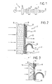
- FIG. 2 illustrates an embodiment of the electrostatic micro-shutter device 4.
- a film 9 made of transparent conductive material for example indium tin oxide (ITO), which has a thickness of a few tens or hundreds of nanometres and is obtained, for example, by means of vapour deposition, spin coating, silk-screen printing, or dipping.
- the film 9 constitutes a first electrode of the device, which is common to all the micro-shutters.
- the layer 10 can be formed by a dielectric material, preferably tantalum oxide (Ta 2 O 5 ) or by a ferro-electric material, for example lead zircono-titanate (PZT) or the like (e.g., lantanates).
- a dielectric material preferably tantalum oxide (Ta 2 O 5 ) or by a ferro-electric material, for example lead zircono-titanate (PZT) or the like (e.g., lantanates).
- PZT lead zircono-titanate
- Set on top of the dielectric layer 10, in a plane orthogonal to the direction of the light beam, is an aligned series or a matrix array of mobile petals 11, each formed, for example, by a dielectric film, on which a metallized layer 12 functioning as second electrode is applied.
- Each petal 11 has one end secured to the layer 10 and, in its undeformed condition, assumes a curled-up configuration, in such a way as to enable passage of light through the respective portion of the substrate 8.
- the device comprises electric power supply means for applying a potential difference between the first electrode 9 and the second electrode 12 of a petal 11 selected. Following upon application of the voltage, the petal distends over the layer 10 adhering thereto by electrostatic effect, and consequently obstructing the passage of light through the respective portion of substrate.
- Figure 3 illustrates a variant in which the electrode 9 can be made of a low-cost non-transparent metal material, in which case there is provided a micro-window 13 in a position corresponding to each petal 11.
- the substrate 8 may be made of non-transparent material and have an opening 14 in a position corresponding to each petal.
- the insulating layer 10 preferably has a hole 15 facing the openings 13, 14.
- FIG. 4 a first embodiment of the spectrophotometer according to the invention will be described.
- the optical filters, designated by the reference number 20 are arranged, according to an aligned arrangement or a matrix array, within the same substrate 8 of the set of electrostatic micro-shutters 7.
- the structure of the micro-shutters 7 may be altogether identical to the one illustrated in Figure 2, and hence, in Figures 4, 5, parts corresponding to those illustrated in Figures 1-3 are designated by the same reference numbers.
- the micro-shutters 7 have an arrangement identical to that of the micro-filters 20 (aligned set or matrix array), in a plane orthogonal to the direction of the light beam L coming from the source (not visible in Figures 4 and 5).
- the substrate 8 may be made of a non-transparent material, and the same applies to the layer of the electrode 9 and the insulating layer 10, in so far as the latter have the openings 13, 15 and define micro-windows in positions corresponding to each micro-filter 20.
- each micro-filter 20 is set within the substrate 8, i.e., it is mounted in a position corresponding to a through cavity made in the substrate, thus creating an extremely simple and compact structure.
- the outputs of the optical micro-filters 20 are connected by means of coupling elements 21, of any known type, to respective ends of optical fibres 22, the opposite ends of which converge in an optical-coupling element 23, which is also of any known type, for coupling with sensor means 24, of any known type, preferably formed by a single pyro-electric sensor or by a single photodiode, the output signals of which are sent to a processing and control unit 25, which also sends signals 26 for controlling the electric power supply to the various micro-shutters 7, for enabling selection of the desired wavelengths, and signals 27 to display means (not illustrated) for displaying the results of the processing operations.
- control unit 25 carries out activation of the micro-shutters 7 for the purpose of selecting each time the desired wavelengths. Only the micro-shutter 7 that each time is in the open condition enables passage of light L, which undergoes filtering by the corresponding micro-filter 20. The corresponding optical fibre 22 hence conducts to the sensor 24 only the radiation having the desired wavelength. The signals at output from the sensor means 24 are sent to the control unit 25, which displays the results obtained.
- a dark phase in which all the shutters are closed.
- Figure 5 illustrates an alternative embodiment, which differs from that of Figure 4 only in the way in which the radiation leaving the micro-filters 20 are guided to the sensor 24.
- the optical-fibre system 22 of Figure 4 is replaced by a single element 28 constituting a light guide, of type in itself known, designed to convey the light exploiting phenomena of total inner reflection (T.I.R.).
- the sensor 24 is, in this case, set at one end of the optical guide 28, with consequent further reduction of the dimensions of the overall device.
- the light beam L directed onto the array of micro-shutters it is preferable for the light beam L directed onto the array of micro-shutters to have an inclination with respect to the direction orthogonal to the plane of the array of micro-shutters, as illustrated in Figure 5.
- the fundamental advantage of the present invention as compared to the known solution described above lies in the fact that the need for a prism element upstream of the array of micro-shutters for splitting the beam into its components is eliminated completely, the selection made by the micro-shutters being obtained already on specific wavelengths of the radiation, thanks to the use of the micro-filters, with the consequence of a overall structure of the spectrophotometer that is more simple and more compact.
Landscapes
- Physics & Mathematics (AREA)
- Spectroscopy & Molecular Physics (AREA)
- General Physics & Mathematics (AREA)
- Spectrometry And Color Measurement (AREA)
- Investigating Or Analysing Materials By Optical Means (AREA)
- Investigating, Analyzing Materials By Fluorescence Or Luminescence (AREA)
Claims (7)
- Spectrophotomètre, comprenant :- une source de lumière (2) ;- des moyens séparateurs (20) pour séparer le faisceau lumineux venant de la source (2) en différentes composantes correspondant à des longueurs d'onde différentes ;- des moyens sélecteurs (7) pour sélectionner une ou plusieurs des composantes du faisceau lumineux qui sont générées par lesdits moyens séparateurs (20) ;- des moyens capteurs (24) pour recevoir la composante sélectionnée par lesdits moyens sélecteurs (7) et pour émettre en sortie des signaux électriques indiquant la longueur d'onde du rayonnement reçu ;dans lequel- lesdits moyens séparateurs sont formés seulement par une pluralité de filtres optiques (20), qui peuvent sélectionner différentes longueurs d'onde, etlesdits moyens sélecteurs comprennent une pluralité de micro-obturateurs (7) qui peuvent être actionnés indépendamment les uns des autres, auxquels sont respectivement associés les filtres optiques (20) susmentionnés,
de sorte que le faisceau lumineux n'est pas divisé dans les différentes longueurs d'onde en amont des moyens sélecteurs,
ledit spectrophotomètre étant caractérisé en ce que- lesdits micro-obturateurs (7) sont des micro-obturateurs électrostatiques,- lesdits micro-obturateurs électrostatiques comprennent : un substrat commun (8) ; un couche conductrice électrique (9) servant d'électrode commune, appliquée sur une face du substrat (8) ; une couche isolante (10) placée par-dessus l'électrode commune (9) ; et une pluralité d'électrodes à film mince séparées (11) ayant chacune une extrémité ancrée à la couche isolante (10) et la partie restante mobile entre un état de repos, dans lequel l'électrode (11) laisse libre le passage de la lumière (L) à travers le substrat (8) et un état activé dans lequel elle adhère au substrat, dans lequel le passage de la lumière est obstrué,- lesdits filtres optiques (20) sont agencés dans le substrat (8) susmentionné,- lesdits moyens capteurs consistent en un unique capteur formé, par exemple, d'un capteur pyroélectrique ou d'une diode photoélectrique,- et en ce qu'il est prévu des moyens pour guider le rayonnement séparé par lesdits micro-filtres (20) en direction dudit capteur unique (24). - Spectrophotomètre selon la revendication 1, caractérisé en ce que lesdits moyens de guidage sont formés par une série de fibres optiques (22) qui s'étendent depuis les sorties des filtres optiques (20) jusqu'aux moyens capteurs (23) susmentionnés.
- Spectrophotomètre selon la revendication 2, caractérisé en ce qu'aux extrémités de chaque fibre optique (22) sont prévus des moyens de couplage optique (21, 23) pour un couplage, respectivement, avec un filtre optique (20) et avec les moyens capteurs (24) susmentionnés.
- Spectrophotomètre selon la revendication 1, caractérisé en ce que lesdits moyens de guidage sont formés par un élément guide de lumière (28) qui exploite le phénomène de réflexion interne totale (TIR).
- Spectrophotomètre selon la revendication 4, caractérisé en ce que lesdits moyens de guidage de lumière (28) prennent la forme d'un jeu de plaques parallèle à et proche de l'agencement des filtres optiques (20) susmentionnés, avec les moyens capteurs (24) placés à une extrémité de ladite plaque (28).
- Spectrophotomètre selon chacune des revendications précédentes, caractérisé en ce que les filtres optiques (20) sont d'un type à interférence.
- Spectrophotomètre selon la revendication 1, caractérisé en ce qu'il comprend une unité de commande électronique (25) pour recevoir et traiter les signaux à la sortie desdits moyens capteurs (24), pour émettre en sortie des signaux (27) à des moyens pour afficher les résultats de l'opération de traitement, et des signaux de commande (26) pour contrôler l'alimentation électrique des micro-obturateurs électrostatiques (7).
Applications Claiming Priority (2)
| Application Number | Priority Date | Filing Date | Title |
|---|---|---|---|
| IT001034A ITTO20031034A1 (it) | 2003-12-23 | 2003-12-23 | Spettrofotometro con micro-filtri. |
| ITTO20031034 | 2003-12-23 |
Publications (3)
| Publication Number | Publication Date |
|---|---|
| EP1548414A2 EP1548414A2 (fr) | 2005-06-29 |
| EP1548414A3 EP1548414A3 (fr) | 2005-09-07 |
| EP1548414B1 true EP1548414B1 (fr) | 2006-12-20 |
Family
ID=34531945
Family Applications (1)
| Application Number | Title | Priority Date | Filing Date |
|---|---|---|---|
| EP04022758A Expired - Lifetime EP1548414B1 (fr) | 2003-12-23 | 2004-09-24 | Spectrophotomètre utilisant des filtres optiques et des obturateurs électrostatiques |
Country Status (6)
| Country | Link |
|---|---|
| US (1) | US7286233B2 (fr) |
| EP (1) | EP1548414B1 (fr) |
| AT (1) | ATE349002T1 (fr) |
| DE (1) | DE602004003778T2 (fr) |
| ES (1) | ES2277181T3 (fr) |
| IT (1) | ITTO20031034A1 (fr) |
Families Citing this family (14)
| Publication number | Priority date | Publication date | Assignee | Title |
|---|---|---|---|---|
| ITTO20030982A1 (it) * | 2003-12-05 | 2005-06-06 | Fiat Ricerche | Sistema di controllo delle emissioni nocive nei gas di scarico di un motore a combustione interna di autoveicolo, mediante spettrometria ir a bordo veicolo. |
| AU2007236539A1 (en) * | 2006-04-10 | 2007-10-18 | Mycrolab Pty Ltd, | Imaging apparatus with a plurality of shutter elements |
| DE102011004494A1 (de) * | 2011-02-22 | 2012-08-23 | Carl Zeiss Smt Gmbh | Variabler Filter |
| GB2510777A (en) | 2011-11-03 | 2014-08-13 | Verifood Ltd | Low - cost spectrometry system for end - user analysis |
| GB2529070B (en) | 2013-08-02 | 2017-07-12 | Verifood Ltd | Spectrometer comprising a plurality of isolated optical paths |
| JP2017505901A (ja) | 2014-01-03 | 2017-02-23 | ベリフード, リミテッドVerifood, Ltd. | 分光システム、方法、および用途 |
| CN107250739A (zh) | 2014-10-23 | 2017-10-13 | 威利食品有限公司 | 手持式光谱仪的附件 |
| WO2016125164A2 (fr) | 2015-02-05 | 2016-08-11 | Verifood, Ltd. | Applications d'un système de spectrométrie |
| WO2016125165A2 (fr) | 2015-02-05 | 2016-08-11 | Verifood, Ltd. | Système de spectrométrie comprenant un faisceau de visée visible |
| US10066990B2 (en) | 2015-07-09 | 2018-09-04 | Verifood, Ltd. | Spatially variable filter systems and methods |
| US10203246B2 (en) | 2015-11-20 | 2019-02-12 | Verifood, Ltd. | Systems and methods for calibration of a handheld spectrometer |
| EP3488204A4 (fr) | 2016-07-20 | 2020-07-22 | Verifood Ltd. | Accessoires pour spectromètre portatif |
| US10791933B2 (en) | 2016-07-27 | 2020-10-06 | Verifood, Ltd. | Spectrometry systems, methods, and applications |
| WO2020075036A1 (fr) | 2018-10-08 | 2020-04-16 | Verifood Ltd. | Accessoires pour spectromètres optiques |
Family Cites Families (11)
| Publication number | Priority date | Publication date | Assignee | Title |
|---|---|---|---|---|
| US5233459A (en) * | 1991-03-06 | 1993-08-03 | Massachusetts Institute Of Technology | Electric display device |
| US5570180A (en) * | 1993-08-27 | 1996-10-29 | Minolta Co., Ltd. | Spectrometer provided with an optical shutter |
| US5781331A (en) * | 1997-01-24 | 1998-07-14 | Roxburgh Ltd. | Optical microshutter array |
| US6191860B1 (en) * | 1998-02-06 | 2001-02-20 | Orsense Ltd. | Optical shutter, spectrometer and method for spectral analysis |
| IT1307130B1 (it) * | 1999-02-02 | 2001-10-29 | Fiat Ricerche | Dispositivo ottico a micro-otturatori o micro-specchi ad effettomagnetico. |
| US7123844B2 (en) * | 1999-04-06 | 2006-10-17 | Myrick Michael L | Optical computational system |
| JP3643508B2 (ja) * | 1999-09-28 | 2005-04-27 | 株式会社東芝 | 可動フィルム型表示装置 |
| US6707548B2 (en) * | 2001-02-08 | 2004-03-16 | Array Bioscience Corporation | Systems and methods for filter based spectrographic analysis |
| ITTO20010275A1 (it) * | 2001-03-23 | 2002-09-23 | Fiat Ricerche | Spettrofotometro con micro-otturatori elettrostatici. |
| US6630999B2 (en) * | 2001-05-01 | 2003-10-07 | Optical Coating Laboratory, Inc. | Color measuring sensor assembly for spectrometer devices |
| US7705826B2 (en) * | 2002-02-09 | 2010-04-27 | New Visual Media Group, L.L.C. | Flexible video displays and their manufacture |
-
2003
- 2003-12-23 IT IT001034A patent/ITTO20031034A1/it unknown
-
2004
- 2004-09-24 EP EP04022758A patent/EP1548414B1/fr not_active Expired - Lifetime
- 2004-09-24 DE DE602004003778T patent/DE602004003778T2/de not_active Expired - Lifetime
- 2004-09-24 ES ES04022758T patent/ES2277181T3/es not_active Expired - Lifetime
- 2004-09-24 AT AT04022758T patent/ATE349002T1/de not_active IP Right Cessation
- 2004-11-01 US US10/976,799 patent/US7286233B2/en not_active Expired - Fee Related
Also Published As
| Publication number | Publication date |
|---|---|
| ITTO20031034A1 (it) | 2005-06-24 |
| ES2277181T3 (es) | 2007-07-01 |
| US20050134855A1 (en) | 2005-06-23 |
| US7286233B2 (en) | 2007-10-23 |
| ATE349002T1 (de) | 2007-01-15 |
| DE602004003778T2 (de) | 2007-10-11 |
| EP1548414A2 (fr) | 2005-06-29 |
| DE602004003778D1 (de) | 2007-02-01 |
| EP1548414A3 (fr) | 2005-09-07 |
Similar Documents
| Publication | Publication Date | Title |
|---|---|---|
| EP1548414B1 (fr) | Spectrophotomètre utilisant des filtres optiques et des obturateurs électrostatiques | |
| EP2118628B1 (fr) | Dispositif de photodétection | |
| US20150177510A1 (en) | Optical filter, optical filter module, spectrometric measurement apparatus, and optical apparatus | |
| JP5625614B2 (ja) | 光フィルター、光フィルターモジュール、分光測定器および光機器 | |
| US6891676B2 (en) | Tunable spectral filter | |
| US6342960B1 (en) | Wavelength division multiplex transmitter | |
| US6233087B1 (en) | Electro-mechanical grating device | |
| JP6264810B2 (ja) | 干渉フィルター、光学フィルターデバイス、光学モジュール、及び電子機器 | |
| CN104656176B (zh) | 光学滤波器装置、光学模块以及电子设备 | |
| US20040114246A1 (en) | Hybrid opto-mechanical component | |
| CN100388021C (zh) | 动态增益均衡器 | |
| WO2019016481A1 (fr) | Dispositif optoelectronique | |
| US20030081319A1 (en) | Tunable optical filter | |
| WO2019016482A1 (fr) | Dispositif optoelectronique | |
| EP2835678B1 (fr) | Filtre optique, module optique, appareil électronique et procédé de fabrication de filtre optique | |
| US6108461A (en) | Contact image sensor and method of manufacturing the same | |
| US7057795B2 (en) | Micro-structures with individually addressable ribbon pairs | |
| FR2558628A1 (fr) | Dispositif de commutation/affichage | |
| JP5999159B2 (ja) | 光フィルター、光フィルターモジュール、分光測定器および光機器 | |
| KR102768187B1 (ko) | 광 검출 장치 | |
| US5254849A (en) | Image reading apparatus having light shielding element disposed between light emitting elements | |
| EP1243902B1 (fr) | Spectrophotomètre comportant des micro-obturateurs | |
| CA2384998A1 (fr) | Element optique a selectivite de longueur d'onde | |
| JP2012108220A (ja) | 光フィルターおよび光機器 | |
| WO2009144644A1 (fr) | Système de détecteur de lumière |
Legal Events
| Date | Code | Title | Description |
|---|---|---|---|
| PUAI | Public reference made under article 153(3) epc to a published international application that has entered the european phase |
Free format text: ORIGINAL CODE: 0009012 |
|
| AK | Designated contracting states |
Kind code of ref document: A2 Designated state(s): AT BE BG CH CY CZ DE DK EE ES FI FR GB GR HU IE IT LI LU MC NL PL PT RO SE SI SK TR |
|
| AX | Request for extension of the european patent |
Extension state: AL HR LT LV MK |
|
| PUAL | Search report despatched |
Free format text: ORIGINAL CODE: 0009013 |
|
| AK | Designated contracting states |
Kind code of ref document: A3 Designated state(s): AT BE BG CH CY CZ DE DK EE ES FI FR GB GR HU IE IT LI LU MC NL PL PT RO SE SI SK TR |
|
| AX | Request for extension of the european patent |
Extension state: AL HR LT LV MK |
|
| 17P | Request for examination filed |
Effective date: 20060118 |
|
| AKX | Designation fees paid |
Designated state(s): AT BE BG CH CY CZ DE DK EE ES FI FR GB GR HU IE IT LI LU MC NL PL PT RO SE SI SK TR |
|
| GRAP | Despatch of communication of intention to grant a patent |
Free format text: ORIGINAL CODE: EPIDOSNIGR1 |
|
| GRAS | Grant fee paid |
Free format text: ORIGINAL CODE: EPIDOSNIGR3 |
|
| GRAA | (expected) grant |
Free format text: ORIGINAL CODE: 0009210 |
|
| AK | Designated contracting states |
Kind code of ref document: B1 Designated state(s): AT BE BG CH CY CZ DE DK EE ES FI FR GB GR HU IE IT LI LU MC NL PL PT RO SE SI SK TR |
|
| PG25 | Lapsed in a contracting state [announced via postgrant information from national office to epo] |
Ref country code: FI Free format text: LAPSE BECAUSE OF FAILURE TO SUBMIT A TRANSLATION OF THE DESCRIPTION OR TO PAY THE FEE WITHIN THE PRESCRIBED TIME-LIMIT Effective date: 20061220 Ref country code: PL Free format text: LAPSE BECAUSE OF FAILURE TO SUBMIT A TRANSLATION OF THE DESCRIPTION OR TO PAY THE FEE WITHIN THE PRESCRIBED TIME-LIMIT Effective date: 20061220 Ref country code: DK Free format text: LAPSE BECAUSE OF FAILURE TO SUBMIT A TRANSLATION OF THE DESCRIPTION OR TO PAY THE FEE WITHIN THE PRESCRIBED TIME-LIMIT Effective date: 20061220 Ref country code: RO Free format text: LAPSE BECAUSE OF FAILURE TO SUBMIT A TRANSLATION OF THE DESCRIPTION OR TO PAY THE FEE WITHIN THE PRESCRIBED TIME-LIMIT Effective date: 20061220 Ref country code: LI Free format text: LAPSE BECAUSE OF FAILURE TO SUBMIT A TRANSLATION OF THE DESCRIPTION OR TO PAY THE FEE WITHIN THE PRESCRIBED TIME-LIMIT Effective date: 20061220 Ref country code: SI Free format text: LAPSE BECAUSE OF FAILURE TO SUBMIT A TRANSLATION OF THE DESCRIPTION OR TO PAY THE FEE WITHIN THE PRESCRIBED TIME-LIMIT Effective date: 20061220 Ref country code: CZ Free format text: LAPSE BECAUSE OF FAILURE TO SUBMIT A TRANSLATION OF THE DESCRIPTION OR TO PAY THE FEE WITHIN THE PRESCRIBED TIME-LIMIT Effective date: 20061220 Ref country code: AT Free format text: LAPSE BECAUSE OF FAILURE TO SUBMIT A TRANSLATION OF THE DESCRIPTION OR TO PAY THE FEE WITHIN THE PRESCRIBED TIME-LIMIT Effective date: 20061220 Ref country code: BE Free format text: LAPSE BECAUSE OF FAILURE TO SUBMIT A TRANSLATION OF THE DESCRIPTION OR TO PAY THE FEE WITHIN THE PRESCRIBED TIME-LIMIT Effective date: 20061220 Ref country code: NL Free format text: LAPSE BECAUSE OF FAILURE TO SUBMIT A TRANSLATION OF THE DESCRIPTION OR TO PAY THE FEE WITHIN THE PRESCRIBED TIME-LIMIT Effective date: 20061220 Ref country code: SK Free format text: LAPSE BECAUSE OF FAILURE TO SUBMIT A TRANSLATION OF THE DESCRIPTION OR TO PAY THE FEE WITHIN THE PRESCRIBED TIME-LIMIT Effective date: 20061220 Ref country code: CH Free format text: LAPSE BECAUSE OF FAILURE TO SUBMIT A TRANSLATION OF THE DESCRIPTION OR TO PAY THE FEE WITHIN THE PRESCRIBED TIME-LIMIT Effective date: 20061220 |
|
| REG | Reference to a national code |
Ref country code: GB Ref legal event code: FG4D |
|
| REG | Reference to a national code |
Ref country code: CH Ref legal event code: EP |
|
| REF | Corresponds to: |
Ref document number: 602004003778 Country of ref document: DE Date of ref document: 20070201 Kind code of ref document: P |
|
| REG | Reference to a national code |
Ref country code: IE Ref legal event code: FG4D |
|
| PG25 | Lapsed in a contracting state [announced via postgrant information from national office to epo] |
Ref country code: BG Free format text: LAPSE BECAUSE OF FAILURE TO SUBMIT A TRANSLATION OF THE DESCRIPTION OR TO PAY THE FEE WITHIN THE PRESCRIBED TIME-LIMIT Effective date: 20070320 |
|
| REG | Reference to a national code |
Ref country code: SE Ref legal event code: TRGR |
|
| PG25 | Lapsed in a contracting state [announced via postgrant information from national office to epo] |
Ref country code: PT Free format text: LAPSE BECAUSE OF FAILURE TO SUBMIT A TRANSLATION OF THE DESCRIPTION OR TO PAY THE FEE WITHIN THE PRESCRIBED TIME-LIMIT Effective date: 20070424 |
|
| ET | Fr: translation filed | ||
| NLV1 | Nl: lapsed or annulled due to failure to fulfill the requirements of art. 29p and 29m of the patents act | ||
| REG | Reference to a national code |
Ref country code: CH Ref legal event code: PL |
|
| REG | Reference to a national code |
Ref country code: ES Ref legal event code: FG2A Ref document number: 2277181 Country of ref document: ES Kind code of ref document: T3 |
|
| PLBE | No opposition filed within time limit |
Free format text: ORIGINAL CODE: 0009261 |
|
| STAA | Information on the status of an ep patent application or granted ep patent |
Free format text: STATUS: NO OPPOSITION FILED WITHIN TIME LIMIT |
|
| 26N | No opposition filed |
Effective date: 20070921 |
|
| PG25 | Lapsed in a contracting state [announced via postgrant information from national office to epo] |
Ref country code: GR Free format text: LAPSE BECAUSE OF FAILURE TO SUBMIT A TRANSLATION OF THE DESCRIPTION OR TO PAY THE FEE WITHIN THE PRESCRIBED TIME-LIMIT Effective date: 20070321 Ref country code: MC Free format text: LAPSE BECAUSE OF NON-PAYMENT OF DUE FEES Effective date: 20070930 |
|
| PG25 | Lapsed in a contracting state [announced via postgrant information from national office to epo] |
Ref country code: IE Free format text: LAPSE BECAUSE OF NON-PAYMENT OF DUE FEES Effective date: 20070924 |
|
| PG25 | Lapsed in a contracting state [announced via postgrant information from national office to epo] |
Ref country code: EE Free format text: LAPSE BECAUSE OF FAILURE TO SUBMIT A TRANSLATION OF THE DESCRIPTION OR TO PAY THE FEE WITHIN THE PRESCRIBED TIME-LIMIT Effective date: 20061220 |
|
| PG25 | Lapsed in a contracting state [announced via postgrant information from national office to epo] |
Ref country code: CY Free format text: LAPSE BECAUSE OF FAILURE TO SUBMIT A TRANSLATION OF THE DESCRIPTION OR TO PAY THE FEE WITHIN THE PRESCRIBED TIME-LIMIT Effective date: 20061220 Ref country code: LU Free format text: LAPSE BECAUSE OF NON-PAYMENT OF DUE FEES Effective date: 20070924 |
|
| PG25 | Lapsed in a contracting state [announced via postgrant information from national office to epo] |
Ref country code: HU Free format text: LAPSE BECAUSE OF FAILURE TO SUBMIT A TRANSLATION OF THE DESCRIPTION OR TO PAY THE FEE WITHIN THE PRESCRIBED TIME-LIMIT Effective date: 20070621 Ref country code: TR Free format text: LAPSE BECAUSE OF FAILURE TO SUBMIT A TRANSLATION OF THE DESCRIPTION OR TO PAY THE FEE WITHIN THE PRESCRIBED TIME-LIMIT Effective date: 20061220 |
|
| PGFP | Annual fee paid to national office [announced via postgrant information from national office to epo] |
Ref country code: FR Payment date: 20100921 Year of fee payment: 7 Ref country code: IT Payment date: 20100906 Year of fee payment: 7 Ref country code: SE Payment date: 20100913 Year of fee payment: 7 |
|
| PGFP | Annual fee paid to national office [announced via postgrant information from national office to epo] |
Ref country code: GB Payment date: 20100922 Year of fee payment: 7 |
|
| PGFP | Annual fee paid to national office [announced via postgrant information from national office to epo] |
Ref country code: DE Payment date: 20100922 Year of fee payment: 7 |
|
| PGFP | Annual fee paid to national office [announced via postgrant information from national office to epo] |
Ref country code: ES Payment date: 20101018 Year of fee payment: 7 |
|
| GBPC | Gb: european patent ceased through non-payment of renewal fee |
Effective date: 20110924 |
|
| PG25 | Lapsed in a contracting state [announced via postgrant information from national office to epo] |
Ref country code: IT Free format text: LAPSE BECAUSE OF NON-PAYMENT OF DUE FEES Effective date: 20110924 |
|
| REG | Reference to a national code |
Ref country code: FR Ref legal event code: ST Effective date: 20120531 |
|
| REG | Reference to a national code |
Ref country code: SE Ref legal event code: EUG |
|
| REG | Reference to a national code |
Ref country code: DE Ref legal event code: R119 Ref document number: 602004003778 Country of ref document: DE Effective date: 20120403 |
|
| PG25 | Lapsed in a contracting state [announced via postgrant information from national office to epo] |
Ref country code: DE Free format text: LAPSE BECAUSE OF NON-PAYMENT OF DUE FEES Effective date: 20120403 |
|
| PG25 | Lapsed in a contracting state [announced via postgrant information from national office to epo] |
Ref country code: FR Free format text: LAPSE BECAUSE OF NON-PAYMENT OF DUE FEES Effective date: 20110930 Ref country code: GB Free format text: LAPSE BECAUSE OF NON-PAYMENT OF DUE FEES Effective date: 20110924 |
|
| REG | Reference to a national code |
Ref country code: ES Ref legal event code: FD2A Effective date: 20130417 |
|
| PG25 | Lapsed in a contracting state [announced via postgrant information from national office to epo] |
Ref country code: SE Free format text: LAPSE BECAUSE OF NON-PAYMENT OF DUE FEES Effective date: 20110925 Ref country code: ES Free format text: LAPSE BECAUSE OF NON-PAYMENT OF DUE FEES Effective date: 20110925 |