EP1548414A2 - Spektrophotometer mit optischen Filtern und elektrostatischen Verschlüssen - Google Patents
Spektrophotometer mit optischen Filtern und elektrostatischen Verschlüssen Download PDFInfo
- Publication number
- EP1548414A2 EP1548414A2 EP04022758A EP04022758A EP1548414A2 EP 1548414 A2 EP1548414 A2 EP 1548414A2 EP 04022758 A EP04022758 A EP 04022758A EP 04022758 A EP04022758 A EP 04022758A EP 1548414 A2 EP1548414 A2 EP 1548414A2
- Authority
- EP
- European Patent Office
- Prior art keywords
- micro
- filters
- spectrophotometer according
- spectrophotometer
- shutters
- Prior art date
- Legal status (The legal status is an assumption and is not a legal conclusion. Google has not performed a legal analysis and makes no representation as to the accuracy of the status listed.)
- Granted
Links
Images

Classifications
-
- G—PHYSICS
- G01—MEASURING; TESTING
- G01J—MEASUREMENT OF INTENSITY, VELOCITY, SPECTRAL CONTENT, POLARISATION, PHASE OR PULSE CHARACTERISTICS OF INFRARED, VISIBLE OR ULTRAVIOLET LIGHT; COLORIMETRY; RADIATION PYROMETRY
- G01J3/00—Spectrometry; Spectrophotometry; Monochromators; Measuring colours
- G01J3/46—Measurement of colour; Colour measuring devices, e.g. colorimeters
- G01J3/50—Measurement of colour; Colour measuring devices, e.g. colorimeters using electric radiation detectors
- G01J3/51—Measurement of colour; Colour measuring devices, e.g. colorimeters using electric radiation detectors using colour filters
-
- G—PHYSICS
- G01—MEASURING; TESTING
- G01J—MEASUREMENT OF INTENSITY, VELOCITY, SPECTRAL CONTENT, POLARISATION, PHASE OR PULSE CHARACTERISTICS OF INFRARED, VISIBLE OR ULTRAVIOLET LIGHT; COLORIMETRY; RADIATION PYROMETRY
- G01J3/00—Spectrometry; Spectrophotometry; Monochromators; Measuring colours
- G01J3/02—Details
- G01J3/04—Slit arrangements slit adjustment
-
- G—PHYSICS
- G01—MEASURING; TESTING
- G01J—MEASUREMENT OF INTENSITY, VELOCITY, SPECTRAL CONTENT, POLARISATION, PHASE OR PULSE CHARACTERISTICS OF INFRARED, VISIBLE OR ULTRAVIOLET LIGHT; COLORIMETRY; RADIATION PYROMETRY
- G01J3/00—Spectrometry; Spectrophotometry; Monochromators; Measuring colours
- G01J3/28—Investigating the spectrum
- G01J3/30—Measuring the intensity of spectral lines directly on the spectrum itself
- G01J3/32—Investigating bands of a spectrum in sequence by a single detector
Definitions
- the present invention relates to the spectrophotometers.
- the spectrophotometer known from said document uses a separator element of any known type (for example a prism or a grating) to separate the light beam at output from the source into its components corresponding to the different wavelengths.
- the selection of one or more of the components of the light beam that are separated by means of said separator element is performed by means of an aligned set or a matrix array of electrostatic micro-shutters.
- the radiation selected by means of the electrostatic micro-shutters is made to converge on sensor means formed by a single sensor, for example a single photodiode, so as to avoid the high costs and complications of known solutions, which envisage sensor means formed by an array of photodiodes.
- the purpose of the present invention is to propose a solution alternative to the known solution described above, which will be characterized by constructional simplicity, low production costs, and extremely small dimensions, with a view to favouring use thereof, for example, in applications such as the detection of the composition of the exhaust gases of the engine of a motor vehicle by means of a spectrophotometer provided on board said vehicle.
- the subject of the invention is a spectrophotometer presenting all the characteristics that have been referred to at the beginning of the present description and further characterized in that there are not envisaged means for splitting the light beam into the different wavelengths upstream of the selector means, the aforesaid separator means being formed only by a plurality of optical micro-filters that select different wavelengths.
- micro- filters enables complete elimination of the need for the separator element (prism or grating) that was provided in the known solution referred to above, with consequent advantages of greater simplicity and smaller overall dimensions of the spectrophotometer.
- the aforesaid selector means comprise a plurality of micro-shutters that can be actuated independently of one another.
- each of the aforesaid micro-filters is associated to a respective micro-shutter so as to obtain an extremely compact assembly, capable of selecting the wavelengths of interest without any need for additional elements for splitting the beam into its components, as in the case of the known solution.
- the aforesaid optical micro-filters are of the interference type.
- the aforesaid micro-filters are electrostatic micro-shutters.
- the electrostatic micro-shutters comprise a common substrate, an electrically conductive layer, functioning as common electrode, applied on a face of the substrate, an insulating layer, made of dielectric or ferro-electric material, set above the common electrode, and a plurality of separate thin-film electrodes, each having one end anchored to the insulating layer and the remaining part mobile between a position of rest, in which the electrode leaves free a passage for light through the substrate, and a position adherent to the substrate, in which the passage of light is obstructed.
- the aforesaid optical micro-filters are arranged within the substrate of the micro-shutters.
- the sensor means are preferably formed by a single sensor, preferably a pyro-electric sensor, or else a photodiode.
- electronic-control means for receiving and processing the signals at output from the sensor means and for controlling the electric power supply to the individual electrostatic micro-shutters for the purpose of selecting the wavelengths that are each time of interest.
- Said guide means are formed, in a first example of embodiment, by a series of optical fibres that extends from the outputs of the micro-filters up to the aforesaid sensor means.
- coupling elements of any known type, between the ends of the optical fibres and the optical micro-filters, on one side, and between the ends of the optical fibres and the sensor means, on the other.
- the aforesaid means for guiding radiation from the filters selected to the sensor means are formed by a light-guide element that exploits phenomena of total inner reflection (T.I.R.).
- T.I.R. total inner reflection
- the same sublayer could function as light guide if a dielectric layer with appropriate index of refraction is deposited on the face opposite to that of the micro-shutters.
- a further subject the invention is a method for controlling the spectrophotometer described above.
- a dark phase in which all the micro-shutters are closed.
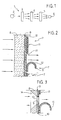
- the reference number 1 designates, as a whole, a spectrophotometer of the type illustrated in the document EP 1 243 902 A1.
- the spectrophotometer 1 comprises a light source 2, and a separator element 3 of any known type, designed to separate the light beam leaving the source 2 into its components corresponding to the different wavelengths.
- Set downstream of the separator device 3 is an electrostatic micro-shutter device 4 that is illustrated in detail in what follows. Said device is designed for selecting a single desired wavelength in the beam emitted by the separator element 3.
- the radiation emitted is then made to converge by an optical element 5 on top of a single sensor 6, of any known type, for example a pyro-electric sensor or a photodiode, designed to emit at output an electrical signal that is a function of the light energy received.
- a single sensor 6 of any known type, for example a pyro-electric sensor or a photodiode, designed to emit at output an electrical signal that is a function of the light energy received.
- FIG. 2 illustrates an embodiment of the electrostatic micro-shutter device 4.
- a film 9 made of transparent conductive material for example indium tin oxide (ITO), which has a thickness of a few tens or hundreds of nanometres and is obtained, for example, by means of vapour deposition, spin coating, silk-screen printing, or dipping.
- the film 9 constitutes a first electrode of the device, which is common to all the micro-shutters.
- the layer 10 can be formed by a dielectric material, preferably tantalum oxide (Ta 2 O 5 ) or by a ferro-electric material, for example lead zircono-titanate (PZT) or the like (e.g., lantanates).
- a dielectric material preferably tantalum oxide (Ta 2 O 5 ) or by a ferro-electric material, for example lead zircono-titanate (PZT) or the like (e.g., lantanates).
- PZT lead zircono-titanate
- Set on top of the dielectric layer 10, in a plane orthogonal to the direction of the light beam, is an aligned series or a matrix array of mobile petals 11, each formed, for example, by a dielectric film, on which a metallized layer 12 functioning as second electrode is applied.
- Each petal 11 has one end secured to the layer 10 and, in its undeformed condition, assumes a curled-up configuration, in such a way as to enable passage of light through the respective portion of the substrate 8.
- the device comprises electric power supply means for applying a potential difference between the first electrode 9 and the second electrode 12 of a petal 11 selected. Following upon application of the voltage, the petal distends over the layer 10 adhering thereto by electrostatic effect, and consequently obstructing the passage of light through the respective portion of substrate.
- Figure 3 illustrates a variant in which the electrode 9 can be made of a low-cost non-transparent metal material, in which case there is provided a micro-window 13 in a position corresponding to each petal 11.
- the substrate 8 may be made of non-transparent material and have an opening 14 in a position corresponding to each petal.
- the insulating layer 10 preferably has a hole 15 facing the openings 13, 14.
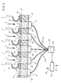
- FIG. 4 a first embodiment of the spectrophotometer according to the invention will be described.
- the optical filters, designated by the reference number 20 are arranged, according to an aligned arrangement or a matrix array, within the same substrate 8 of the set of electrostatic micro-shutters 7.
- the structure of the micro-shutters 7 may be altogether identical to the one illustrated in Figure 2, and hence, in Figures 4, 5, parts corresponding to those illustrated in Figures 1-3 are designated by the same reference numbers.
- the micro-shutters 7 have an arrangement identical to that of the micro-filters 20 (aligned set or matrix array), in a plane orthogonal to the direction of the light beam L coming from the source (not visible in Figures 4 and 5).
- the substrate 8 may be made of a non-transparent material, and the same applies to the layer of the electrode 9 and the insulating layer 10, in so far as the latter have the openings 13, 15 and define micro-windows in positions corresponding to each micro-filter 20.
- each micro-filter 20 is set within the substrate 8, i.e., it is mounted in a position corresponding to a through cavity made in the substrate, thus creating an extremely simple and compact structure.
- the outputs of the optical micro-filters 20 are connected by means of coupling elements 21, of any known type, to respective ends of optical fibres 22, the opposite ends of which converge in an optical-coupling element 23, which is also of any known type, for coupling with sensor means 24, of any known type, preferably formed by a single pyro-electric sensor or by a single photodiode, the output signals of which are sent to a processing and control unit 25, which also sends signals 26 for controlling the electric power supply to the various micro-shutters 7, for enabling selection of the desired wavelengths, and signals 27 to display means (not illustrated) for displaying the results of the processing operations.
- control unit 25 carries out activation of the micro-shutters 7 for the purpose of selecting each time the desired wavelengths. Only the micro-shutter 7 that each time is in the open condition enables passage of light L, which undergoes filtering by the corresponding micro-filter 20. The corresponding optical fibre 22 hence conducts to the sensor 24 only the radiation having the desired wavelength. The signals at output from the sensor means 24 are sent to the control unit 25, which displays the results obtained.
- a dark phase in which all the shutters are closed.
- Figure 5 illustrates an alternative embodiment, which differs from that of Figure 4 only in the way in which the radiation leaving the micro-filters 20 are guided to the sensor 24.
- the optical-fibre system 22 of Figure 4 is replaced by a single element 28 constituting a light guide, of type in itself known, designed to convey the light exploiting phenomena of total inner reflection (T.I.R.).
- the sensor 24 is, in this case, set at one end of the optical guide 28, with consequent further reduction of the dimensions of the overall device.
- the light beam L directed onto the array of micro-shutters it is preferable for the light beam L directed onto the array of micro-shutters to have an inclination with respect to the direction orthogonal to the plane of the array of micro-shutters, as illustrated in Figure 5.
- the fundamental advantage of the present invention as compared to the known solution described above lies in the fact that the need for a prism element upstream of the array of micro-shutters for splitting the beam into its components is eliminated completely, the selection made by the micro-shutters being obtained already on specific wavelengths of the radiation, thanks to the use of the micro-filters, with the consequence of a overall structure of the spectrophotometer that is more simple and more compact.
Landscapes
- Physics & Mathematics (AREA)
- Spectroscopy & Molecular Physics (AREA)
- General Physics & Mathematics (AREA)
- Spectrometry And Color Measurement (AREA)
- Investigating Or Analysing Materials By Optical Means (AREA)
- Investigating, Analyzing Materials By Fluorescence Or Luminescence (AREA)
Applications Claiming Priority (2)
| Application Number | Priority Date | Filing Date | Title |
|---|---|---|---|
| ITTO20031034 | 2003-12-23 | ||
| IT001034A ITTO20031034A1 (it) | 2003-12-23 | 2003-12-23 | Spettrofotometro con micro-filtri. |
Publications (3)
| Publication Number | Publication Date |
|---|---|
| EP1548414A2 true EP1548414A2 (de) | 2005-06-29 |
| EP1548414A3 EP1548414A3 (de) | 2005-09-07 |
| EP1548414B1 EP1548414B1 (de) | 2006-12-20 |
Family
ID=34531945
Family Applications (1)
| Application Number | Title | Priority Date | Filing Date |
|---|---|---|---|
| EP04022758A Expired - Lifetime EP1548414B1 (de) | 2003-12-23 | 2004-09-24 | Spektrophotometer mit optischen Filtern und elektrostatischen Verschlüssen |
Country Status (6)
| Country | Link |
|---|---|
| US (1) | US7286233B2 (de) |
| EP (1) | EP1548414B1 (de) |
| AT (1) | ATE349002T1 (de) |
| DE (1) | DE602004003778T2 (de) |
| ES (1) | ES2277181T3 (de) |
| IT (1) | ITTO20031034A1 (de) |
Cited By (1)
| Publication number | Priority date | Publication date | Assignee | Title |
|---|---|---|---|---|
| US7143575B2 (en) * | 2003-12-05 | 2006-12-05 | C.R.F. Societa Consortile Per Azioni | System for controlling noxious emissions in exhaust gases of an internal-combustion engine of a motor vehicle by means of an IR spectrophotometer on board the motor vehicle |
Families Citing this family (13)
| Publication number | Priority date | Publication date | Assignee | Title |
|---|---|---|---|---|
| CA2648814A1 (en) * | 2006-04-10 | 2007-10-18 | Mycrolab Diagnostics Pty Ltd | Imaging apparatus with a plurality of shutter elements |
| DE102011004494A1 (de) * | 2011-02-22 | 2012-08-23 | Carl Zeiss Smt Gmbh | Variabler Filter |
| WO2013065035A1 (en) | 2011-11-03 | 2013-05-10 | Verifood Ltd. | Low-cost spectrometry system for end-user food analysis |
| CN105593651B (zh) | 2013-08-02 | 2019-06-07 | 威利食品有限公司 | 光谱测定系统和方法、光谱设备和系统 |
| CN106461461A (zh) | 2014-01-03 | 2017-02-22 | 威利食品有限公司 | 光谱测定系统、方法和应用 |
| CN107250739A (zh) | 2014-10-23 | 2017-10-13 | 威利食品有限公司 | 手持式光谱仪的附件 |
| WO2016125164A2 (en) | 2015-02-05 | 2016-08-11 | Verifood, Ltd. | Spectrometry system applications |
| WO2016125165A2 (en) | 2015-02-05 | 2016-08-11 | Verifood, Ltd. | Spectrometry system with visible aiming beam |
| US10066990B2 (en) | 2015-07-09 | 2018-09-04 | Verifood, Ltd. | Spatially variable filter systems and methods |
| US10203246B2 (en) | 2015-11-20 | 2019-02-12 | Verifood, Ltd. | Systems and methods for calibration of a handheld spectrometer |
| WO2018015951A1 (en) | 2016-07-20 | 2018-01-25 | Verifood, Ltd. | Accessories for handheld spectrometer |
| US10791933B2 (en) | 2016-07-27 | 2020-10-06 | Verifood, Ltd. | Spectrometry systems, methods, and applications |
| EP3864384A4 (de) | 2018-10-08 | 2022-06-29 | Verifood Ltd. | Zubehör für optische spektrometer |
Family Cites Families (11)
| Publication number | Priority date | Publication date | Assignee | Title |
|---|---|---|---|---|
| US5233459A (en) * | 1991-03-06 | 1993-08-03 | Massachusetts Institute Of Technology | Electric display device |
| US5570180A (en) * | 1993-08-27 | 1996-10-29 | Minolta Co., Ltd. | Spectrometer provided with an optical shutter |
| US5781331A (en) * | 1997-01-24 | 1998-07-14 | Roxburgh Ltd. | Optical microshutter array |
| US6191860B1 (en) * | 1998-02-06 | 2001-02-20 | Orsense Ltd. | Optical shutter, spectrometer and method for spectral analysis |
| IT1307130B1 (it) * | 1999-02-02 | 2001-10-29 | Fiat Ricerche | Dispositivo ottico a micro-otturatori o micro-specchi ad effettomagnetico. |
| US7123844B2 (en) * | 1999-04-06 | 2006-10-17 | Myrick Michael L | Optical computational system |
| JP3643508B2 (ja) * | 1999-09-28 | 2005-04-27 | 株式会社東芝 | 可動フィルム型表示装置 |
| US6707548B2 (en) * | 2001-02-08 | 2004-03-16 | Array Bioscience Corporation | Systems and methods for filter based spectrographic analysis |
| ITTO20010275A1 (it) * | 2001-03-23 | 2002-09-23 | Fiat Ricerche | Spettrofotometro con micro-otturatori elettrostatici. |
| US6630999B2 (en) * | 2001-05-01 | 2003-10-07 | Optical Coating Laboratory, Inc. | Color measuring sensor assembly for spectrometer devices |
| AU2003215117A1 (en) * | 2002-02-09 | 2003-09-04 | Display Science, Inc. | Flexible video displays and their manufacture |
-
2003
- 2003-12-23 IT IT001034A patent/ITTO20031034A1/it unknown
-
2004
- 2004-09-24 AT AT04022758T patent/ATE349002T1/de not_active IP Right Cessation
- 2004-09-24 ES ES04022758T patent/ES2277181T3/es not_active Expired - Lifetime
- 2004-09-24 EP EP04022758A patent/EP1548414B1/de not_active Expired - Lifetime
- 2004-09-24 DE DE602004003778T patent/DE602004003778T2/de not_active Expired - Lifetime
- 2004-11-01 US US10/976,799 patent/US7286233B2/en not_active Expired - Fee Related
Cited By (1)
| Publication number | Priority date | Publication date | Assignee | Title |
|---|---|---|---|---|
| US7143575B2 (en) * | 2003-12-05 | 2006-12-05 | C.R.F. Societa Consortile Per Azioni | System for controlling noxious emissions in exhaust gases of an internal-combustion engine of a motor vehicle by means of an IR spectrophotometer on board the motor vehicle |
Also Published As
| Publication number | Publication date |
|---|---|
| ATE349002T1 (de) | 2007-01-15 |
| ES2277181T3 (es) | 2007-07-01 |
| US20050134855A1 (en) | 2005-06-23 |
| ITTO20031034A1 (it) | 2005-06-24 |
| EP1548414A3 (de) | 2005-09-07 |
| DE602004003778D1 (de) | 2007-02-01 |
| EP1548414B1 (de) | 2006-12-20 |
| US7286233B2 (en) | 2007-10-23 |
| DE602004003778T2 (de) | 2007-10-11 |
Similar Documents
| Publication | Publication Date | Title |
|---|---|---|
| EP1548414B1 (de) | Spektrophotometer mit optischen Filtern und elektrostatischen Verschlüssen | |
| EP2118628B1 (de) | Optische detektorvorrichtung | |
| US20150177510A1 (en) | Optical filter, optical filter module, spectrometric measurement apparatus, and optical apparatus | |
| US8817267B2 (en) | Optical filter, optical filter module, spectrometric instrument, and optical instrument | |
| EP2873954B1 (de) | Optische Filtervorrichtung, optisches Modul und elektronische Vorrichtung | |
| JP6264810B2 (ja) | 干渉フィルター、光学フィルターデバイス、光学モジュール、及び電子機器 | |
| CN104049293B (zh) | 光学滤波器装置、光学模块以及电子设备 | |
| FR3069378B1 (fr) | Dispositif optoelectronique | |
| EP2650715B1 (de) | Interferenzfilter mit verstellbarer Wellenlänge, optische Filtervorrichtung, optisches Modul und elektronische Vorrichtung | |
| CN102540312B (zh) | 波长可变干涉滤波器、光学组件以及电子设备 | |
| FR3069379B1 (fr) | Dispositif optoelectronique | |
| US20040114246A1 (en) | Hybrid opto-mechanical component | |
| WO2010081814A1 (en) | Display device and use thereof | |
| US20120154791A1 (en) | Surface enhanced raman spectroscopy system | |
| US20030081319A1 (en) | Tunable optical filter | |
| US6108461A (en) | Contact image sensor and method of manufacturing the same | |
| KR20150017678A (ko) | 광 필터, 광학 모듈, 전자 기기 및 광 필터의 제조 방법 | |
| JP5999159B2 (ja) | 光フィルター、光フィルターモジュール、分光測定器および光機器 | |
| EP1243902B1 (de) | Spektrophotometer mit electrostatischen Mikroverschlüssen | |
| US20020135878A1 (en) | Optical element having wavelength selectivity | |
| JP2012108220A (ja) | 光フィルターおよび光機器 | |
| FR2647915A1 (fr) | Appareil photocommande de deviation d'un faisceau lumineux | |
| WO2009144644A1 (en) | Light sensor arrangement | |
| JPH0257926A (ja) | カラーセンサ |
Legal Events
| Date | Code | Title | Description |
|---|---|---|---|
| PUAI | Public reference made under article 153(3) epc to a published international application that has entered the european phase |
Free format text: ORIGINAL CODE: 0009012 |
|
| AK | Designated contracting states |
Kind code of ref document: A2 Designated state(s): AT BE BG CH CY CZ DE DK EE ES FI FR GB GR HU IE IT LI LU MC NL PL PT RO SE SI SK TR |
|
| AX | Request for extension of the european patent |
Extension state: AL HR LT LV MK |
|
| PUAL | Search report despatched |
Free format text: ORIGINAL CODE: 0009013 |
|
| AK | Designated contracting states |
Kind code of ref document: A3 Designated state(s): AT BE BG CH CY CZ DE DK EE ES FI FR GB GR HU IE IT LI LU MC NL PL PT RO SE SI SK TR |
|
| AX | Request for extension of the european patent |
Extension state: AL HR LT LV MK |
|
| 17P | Request for examination filed |
Effective date: 20060118 |
|
| AKX | Designation fees paid |
Designated state(s): AT BE BG CH CY CZ DE DK EE ES FI FR GB GR HU IE IT LI LU MC NL PL PT RO SE SI SK TR |
|
| GRAP | Despatch of communication of intention to grant a patent |
Free format text: ORIGINAL CODE: EPIDOSNIGR1 |
|
| GRAS | Grant fee paid |
Free format text: ORIGINAL CODE: EPIDOSNIGR3 |
|
| GRAA | (expected) grant |
Free format text: ORIGINAL CODE: 0009210 |
|
| AK | Designated contracting states |
Kind code of ref document: B1 Designated state(s): AT BE BG CH CY CZ DE DK EE ES FI FR GB GR HU IE IT LI LU MC NL PL PT RO SE SI SK TR |
|
| PG25 | Lapsed in a contracting state [announced via postgrant information from national office to epo] |
Ref country code: FI Free format text: LAPSE BECAUSE OF FAILURE TO SUBMIT A TRANSLATION OF THE DESCRIPTION OR TO PAY THE FEE WITHIN THE PRESCRIBED TIME-LIMIT Effective date: 20061220 Ref country code: PL Free format text: LAPSE BECAUSE OF FAILURE TO SUBMIT A TRANSLATION OF THE DESCRIPTION OR TO PAY THE FEE WITHIN THE PRESCRIBED TIME-LIMIT Effective date: 20061220 Ref country code: DK Free format text: LAPSE BECAUSE OF FAILURE TO SUBMIT A TRANSLATION OF THE DESCRIPTION OR TO PAY THE FEE WITHIN THE PRESCRIBED TIME-LIMIT Effective date: 20061220 Ref country code: RO Free format text: LAPSE BECAUSE OF FAILURE TO SUBMIT A TRANSLATION OF THE DESCRIPTION OR TO PAY THE FEE WITHIN THE PRESCRIBED TIME-LIMIT Effective date: 20061220 Ref country code: LI Free format text: LAPSE BECAUSE OF FAILURE TO SUBMIT A TRANSLATION OF THE DESCRIPTION OR TO PAY THE FEE WITHIN THE PRESCRIBED TIME-LIMIT Effective date: 20061220 Ref country code: SI Free format text: LAPSE BECAUSE OF FAILURE TO SUBMIT A TRANSLATION OF THE DESCRIPTION OR TO PAY THE FEE WITHIN THE PRESCRIBED TIME-LIMIT Effective date: 20061220 Ref country code: CZ Free format text: LAPSE BECAUSE OF FAILURE TO SUBMIT A TRANSLATION OF THE DESCRIPTION OR TO PAY THE FEE WITHIN THE PRESCRIBED TIME-LIMIT Effective date: 20061220 Ref country code: AT Free format text: LAPSE BECAUSE OF FAILURE TO SUBMIT A TRANSLATION OF THE DESCRIPTION OR TO PAY THE FEE WITHIN THE PRESCRIBED TIME-LIMIT Effective date: 20061220 Ref country code: BE Free format text: LAPSE BECAUSE OF FAILURE TO SUBMIT A TRANSLATION OF THE DESCRIPTION OR TO PAY THE FEE WITHIN THE PRESCRIBED TIME-LIMIT Effective date: 20061220 Ref country code: NL Free format text: LAPSE BECAUSE OF FAILURE TO SUBMIT A TRANSLATION OF THE DESCRIPTION OR TO PAY THE FEE WITHIN THE PRESCRIBED TIME-LIMIT Effective date: 20061220 Ref country code: SK Free format text: LAPSE BECAUSE OF FAILURE TO SUBMIT A TRANSLATION OF THE DESCRIPTION OR TO PAY THE FEE WITHIN THE PRESCRIBED TIME-LIMIT Effective date: 20061220 Ref country code: CH Free format text: LAPSE BECAUSE OF FAILURE TO SUBMIT A TRANSLATION OF THE DESCRIPTION OR TO PAY THE FEE WITHIN THE PRESCRIBED TIME-LIMIT Effective date: 20061220 |
|
| REG | Reference to a national code |
Ref country code: GB Ref legal event code: FG4D |
|
| REG | Reference to a national code |
Ref country code: CH Ref legal event code: EP |
|
| REF | Corresponds to: |
Ref document number: 602004003778 Country of ref document: DE Date of ref document: 20070201 Kind code of ref document: P |
|
| REG | Reference to a national code |
Ref country code: IE Ref legal event code: FG4D |
|
| PG25 | Lapsed in a contracting state [announced via postgrant information from national office to epo] |
Ref country code: BG Free format text: LAPSE BECAUSE OF FAILURE TO SUBMIT A TRANSLATION OF THE DESCRIPTION OR TO PAY THE FEE WITHIN THE PRESCRIBED TIME-LIMIT Effective date: 20070320 |
|
| REG | Reference to a national code |
Ref country code: SE Ref legal event code: TRGR |
|
| PG25 | Lapsed in a contracting state [announced via postgrant information from national office to epo] |
Ref country code: PT Free format text: LAPSE BECAUSE OF FAILURE TO SUBMIT A TRANSLATION OF THE DESCRIPTION OR TO PAY THE FEE WITHIN THE PRESCRIBED TIME-LIMIT Effective date: 20070424 |
|
| ET | Fr: translation filed | ||
| NLV1 | Nl: lapsed or annulled due to failure to fulfill the requirements of art. 29p and 29m of the patents act | ||
| REG | Reference to a national code |
Ref country code: CH Ref legal event code: PL |
|
| REG | Reference to a national code |
Ref country code: ES Ref legal event code: FG2A Ref document number: 2277181 Country of ref document: ES Kind code of ref document: T3 |
|
| PLBE | No opposition filed within time limit |
Free format text: ORIGINAL CODE: 0009261 |
|
| STAA | Information on the status of an ep patent application or granted ep patent |
Free format text: STATUS: NO OPPOSITION FILED WITHIN TIME LIMIT |
|
| 26N | No opposition filed |
Effective date: 20070921 |
|
| PG25 | Lapsed in a contracting state [announced via postgrant information from national office to epo] |
Ref country code: GR Free format text: LAPSE BECAUSE OF FAILURE TO SUBMIT A TRANSLATION OF THE DESCRIPTION OR TO PAY THE FEE WITHIN THE PRESCRIBED TIME-LIMIT Effective date: 20070321 Ref country code: MC Free format text: LAPSE BECAUSE OF NON-PAYMENT OF DUE FEES Effective date: 20070930 |
|
| PG25 | Lapsed in a contracting state [announced via postgrant information from national office to epo] |
Ref country code: IE Free format text: LAPSE BECAUSE OF NON-PAYMENT OF DUE FEES Effective date: 20070924 |
|
| PG25 | Lapsed in a contracting state [announced via postgrant information from national office to epo] |
Ref country code: EE Free format text: LAPSE BECAUSE OF FAILURE TO SUBMIT A TRANSLATION OF THE DESCRIPTION OR TO PAY THE FEE WITHIN THE PRESCRIBED TIME-LIMIT Effective date: 20061220 |
|
| PG25 | Lapsed in a contracting state [announced via postgrant information from national office to epo] |
Ref country code: CY Free format text: LAPSE BECAUSE OF FAILURE TO SUBMIT A TRANSLATION OF THE DESCRIPTION OR TO PAY THE FEE WITHIN THE PRESCRIBED TIME-LIMIT Effective date: 20061220 Ref country code: LU Free format text: LAPSE BECAUSE OF NON-PAYMENT OF DUE FEES Effective date: 20070924 |
|
| PG25 | Lapsed in a contracting state [announced via postgrant information from national office to epo] |
Ref country code: HU Free format text: LAPSE BECAUSE OF FAILURE TO SUBMIT A TRANSLATION OF THE DESCRIPTION OR TO PAY THE FEE WITHIN THE PRESCRIBED TIME-LIMIT Effective date: 20070621 Ref country code: TR Free format text: LAPSE BECAUSE OF FAILURE TO SUBMIT A TRANSLATION OF THE DESCRIPTION OR TO PAY THE FEE WITHIN THE PRESCRIBED TIME-LIMIT Effective date: 20061220 |
|
| PGFP | Annual fee paid to national office [announced via postgrant information from national office to epo] |
Ref country code: FR Payment date: 20100921 Year of fee payment: 7 Ref country code: IT Payment date: 20100906 Year of fee payment: 7 Ref country code: SE Payment date: 20100913 Year of fee payment: 7 |
|
| PGFP | Annual fee paid to national office [announced via postgrant information from national office to epo] |
Ref country code: GB Payment date: 20100922 Year of fee payment: 7 |
|
| PGFP | Annual fee paid to national office [announced via postgrant information from national office to epo] |
Ref country code: DE Payment date: 20100922 Year of fee payment: 7 |
|
| PGFP | Annual fee paid to national office [announced via postgrant information from national office to epo] |
Ref country code: ES Payment date: 20101018 Year of fee payment: 7 |
|
| GBPC | Gb: european patent ceased through non-payment of renewal fee |
Effective date: 20110924 |
|
| PG25 | Lapsed in a contracting state [announced via postgrant information from national office to epo] |
Ref country code: IT Free format text: LAPSE BECAUSE OF NON-PAYMENT OF DUE FEES Effective date: 20110924 |
|
| REG | Reference to a national code |
Ref country code: FR Ref legal event code: ST Effective date: 20120531 |
|
| REG | Reference to a national code |
Ref country code: SE Ref legal event code: EUG |
|
| REG | Reference to a national code |
Ref country code: DE Ref legal event code: R119 Ref document number: 602004003778 Country of ref document: DE Effective date: 20120403 |
|
| PG25 | Lapsed in a contracting state [announced via postgrant information from national office to epo] |
Ref country code: DE Free format text: LAPSE BECAUSE OF NON-PAYMENT OF DUE FEES Effective date: 20120403 |
|
| PG25 | Lapsed in a contracting state [announced via postgrant information from national office to epo] |
Ref country code: FR Free format text: LAPSE BECAUSE OF NON-PAYMENT OF DUE FEES Effective date: 20110930 Ref country code: GB Free format text: LAPSE BECAUSE OF NON-PAYMENT OF DUE FEES Effective date: 20110924 |
|
| REG | Reference to a national code |
Ref country code: ES Ref legal event code: FD2A Effective date: 20130417 |
|
| PG25 | Lapsed in a contracting state [announced via postgrant information from national office to epo] |
Ref country code: SE Free format text: LAPSE BECAUSE OF NON-PAYMENT OF DUE FEES Effective date: 20110925 Ref country code: ES Free format text: LAPSE BECAUSE OF NON-PAYMENT OF DUE FEES Effective date: 20110925 |