EP1548306A1 - Wälzlagereinheit für stützrad - Google Patents
Wälzlagereinheit für stützrad Download PDFInfo
- Publication number
- EP1548306A1 EP1548306A1 EP03794150A EP03794150A EP1548306A1 EP 1548306 A1 EP1548306 A1 EP 1548306A1 EP 03794150 A EP03794150 A EP 03794150A EP 03794150 A EP03794150 A EP 03794150A EP 1548306 A1 EP1548306 A1 EP 1548306A1
- Authority
- EP
- European Patent Office
- Prior art keywords
- ring
- side raceway
- bearing unit
- rolling bearing
- seal
- Prior art date
- Legal status (The legal status is an assumption and is not a legal conclusion. Google has not performed a legal analysis and makes no representation as to the accuracy of the status listed.)
- Ceased
Links
Images




Classifications
-
- F—MECHANICAL ENGINEERING; LIGHTING; HEATING; WEAPONS; BLASTING
- F16—ENGINEERING ELEMENTS AND UNITS; GENERAL MEASURES FOR PRODUCING AND MAINTAINING EFFECTIVE FUNCTIONING OF MACHINES OR INSTALLATIONS; THERMAL INSULATION IN GENERAL
- F16C—SHAFTS; FLEXIBLE SHAFTS; ELEMENTS OR CRANKSHAFT MECHANISMS; ROTARY BODIES OTHER THAN GEARING ELEMENTS; BEARINGS
- F16C19/00—Bearings with rolling contact, for exclusively rotary movement
- F16C19/02—Bearings with rolling contact, for exclusively rotary movement with bearing balls essentially of the same size in one or more circular rows
- F16C19/14—Bearings with rolling contact, for exclusively rotary movement with bearing balls essentially of the same size in one or more circular rows for both radial and axial load
- F16C19/18—Bearings with rolling contact, for exclusively rotary movement with bearing balls essentially of the same size in one or more circular rows for both radial and axial load with two or more rows of balls
- F16C19/181—Bearings with rolling contact, for exclusively rotary movement with bearing balls essentially of the same size in one or more circular rows for both radial and axial load with two or more rows of balls with angular contact
- F16C19/183—Bearings with rolling contact, for exclusively rotary movement with bearing balls essentially of the same size in one or more circular rows for both radial and axial load with two or more rows of balls with angular contact with two rows at opposite angles
- F16C19/184—Bearings with rolling contact, for exclusively rotary movement with bearing balls essentially of the same size in one or more circular rows for both radial and axial load with two or more rows of balls with angular contact with two rows at opposite angles in O-arrangement
- F16C19/186—Bearings with rolling contact, for exclusively rotary movement with bearing balls essentially of the same size in one or more circular rows for both radial and axial load with two or more rows of balls with angular contact with two rows at opposite angles in O-arrangement with three raceways provided integrally on parts other than race rings, e.g. third generation hubs
-
- B—PERFORMING OPERATIONS; TRANSPORTING
- B60—VEHICLES IN GENERAL
- B60B—VEHICLE WHEELS; CASTORS; AXLES FOR WHEELS OR CASTORS; INCREASING WHEEL ADHESION
- B60B27/00—Hubs
-
- B—PERFORMING OPERATIONS; TRANSPORTING
- B60—VEHICLES IN GENERAL
- B60B—VEHICLE WHEELS; CASTORS; AXLES FOR WHEELS OR CASTORS; INCREASING WHEEL ADHESION
- B60B27/00—Hubs
- B60B27/0005—Hubs with ball bearings
-
- B—PERFORMING OPERATIONS; TRANSPORTING
- B60—VEHICLES IN GENERAL
- B60B—VEHICLE WHEELS; CASTORS; AXLES FOR WHEELS OR CASTORS; INCREASING WHEEL ADHESION
- B60B27/00—Hubs
- B60B27/0015—Hubs for driven wheels
- B60B27/0021—Hubs for driven wheels characterised by torque transmission means from drive axle
-
- B—PERFORMING OPERATIONS; TRANSPORTING
- B60—VEHICLES IN GENERAL
- B60B—VEHICLE WHEELS; CASTORS; AXLES FOR WHEELS OR CASTORS; INCREASING WHEEL ADHESION
- B60B27/00—Hubs
- B60B27/0094—Hubs one or more of the bearing races are formed by the hub
-
- B—PERFORMING OPERATIONS; TRANSPORTING
- B60—VEHICLES IN GENERAL
- B60B—VEHICLE WHEELS; CASTORS; AXLES FOR WHEELS OR CASTORS; INCREASING WHEEL ADHESION
- B60B27/00—Hubs
- B60B27/06—Hubs adapted to be fixed on axle
-
- B—PERFORMING OPERATIONS; TRANSPORTING
- B60—VEHICLES IN GENERAL
- B60B—VEHICLE WHEELS; CASTORS; AXLES FOR WHEELS OR CASTORS; INCREASING WHEEL ADHESION
- B60B35/00—Axle units; Parts thereof ; Arrangements for lubrication of axles
- B60B35/12—Torque-transmitting axles
- B60B35/18—Arrangement of bearings
-
- F—MECHANICAL ENGINEERING; LIGHTING; HEATING; WEAPONS; BLASTING
- F16—ENGINEERING ELEMENTS AND UNITS; GENERAL MEASURES FOR PRODUCING AND MAINTAINING EFFECTIVE FUNCTIONING OF MACHINES OR INSTALLATIONS; THERMAL INSULATION IN GENERAL
- F16C—SHAFTS; FLEXIBLE SHAFTS; ELEMENTS OR CRANKSHAFT MECHANISMS; ROTARY BODIES OTHER THAN GEARING ELEMENTS; BEARINGS
- F16C19/00—Bearings with rolling contact, for exclusively rotary movement
- F16C19/02—Bearings with rolling contact, for exclusively rotary movement with bearing balls essentially of the same size in one or more circular rows
- F16C19/14—Bearings with rolling contact, for exclusively rotary movement with bearing balls essentially of the same size in one or more circular rows for both radial and axial load
- F16C19/18—Bearings with rolling contact, for exclusively rotary movement with bearing balls essentially of the same size in one or more circular rows for both radial and axial load with two or more rows of balls
-
- F—MECHANICAL ENGINEERING; LIGHTING; HEATING; WEAPONS; BLASTING
- F16—ENGINEERING ELEMENTS AND UNITS; GENERAL MEASURES FOR PRODUCING AND MAINTAINING EFFECTIVE FUNCTIONING OF MACHINES OR INSTALLATIONS; THERMAL INSULATION IN GENERAL
- F16C—SHAFTS; FLEXIBLE SHAFTS; ELEMENTS OR CRANKSHAFT MECHANISMS; ROTARY BODIES OTHER THAN GEARING ELEMENTS; BEARINGS
- F16C25/00—Bearings for exclusively rotary movement adjustable for wear or play
- F16C25/06—Ball or roller bearings
-
- F—MECHANICAL ENGINEERING; LIGHTING; HEATING; WEAPONS; BLASTING
- F16—ENGINEERING ELEMENTS AND UNITS; GENERAL MEASURES FOR PRODUCING AND MAINTAINING EFFECTIVE FUNCTIONING OF MACHINES OR INSTALLATIONS; THERMAL INSULATION IN GENERAL
- F16C—SHAFTS; FLEXIBLE SHAFTS; ELEMENTS OR CRANKSHAFT MECHANISMS; ROTARY BODIES OTHER THAN GEARING ELEMENTS; BEARINGS
- F16C33/00—Parts of bearings; Special methods for making bearings or parts thereof
- F16C33/72—Sealings
- F16C33/76—Sealings of ball or roller bearings
- F16C33/78—Sealings of ball or roller bearings with a diaphragm, disc, or ring, with or without resilient members
-
- F—MECHANICAL ENGINEERING; LIGHTING; HEATING; WEAPONS; BLASTING
- F16—ENGINEERING ELEMENTS AND UNITS; GENERAL MEASURES FOR PRODUCING AND MAINTAINING EFFECTIVE FUNCTIONING OF MACHINES OR INSTALLATIONS; THERMAL INSULATION IN GENERAL
- F16C—SHAFTS; FLEXIBLE SHAFTS; ELEMENTS OR CRANKSHAFT MECHANISMS; ROTARY BODIES OTHER THAN GEARING ELEMENTS; BEARINGS
- F16C43/00—Assembling bearings
- F16C43/04—Assembling rolling-contact bearings
-
- F—MECHANICAL ENGINEERING; LIGHTING; HEATING; WEAPONS; BLASTING
- F16—ENGINEERING ELEMENTS AND UNITS; GENERAL MEASURES FOR PRODUCING AND MAINTAINING EFFECTIVE FUNCTIONING OF MACHINES OR INSTALLATIONS; THERMAL INSULATION IN GENERAL
- F16C—SHAFTS; FLEXIBLE SHAFTS; ELEMENTS OR CRANKSHAFT MECHANISMS; ROTARY BODIES OTHER THAN GEARING ELEMENTS; BEARINGS
- F16C2326/00—Articles relating to transporting
- F16C2326/01—Parts of vehicles in general
- F16C2326/02—Wheel hubs or castors
-
- F—MECHANICAL ENGINEERING; LIGHTING; HEATING; WEAPONS; BLASTING
- F16—ENGINEERING ELEMENTS AND UNITS; GENERAL MEASURES FOR PRODUCING AND MAINTAINING EFFECTIVE FUNCTIONING OF MACHINES OR INSTALLATIONS; THERMAL INSULATION IN GENERAL
- F16C—SHAFTS; FLEXIBLE SHAFTS; ELEMENTS OR CRANKSHAFT MECHANISMS; ROTARY BODIES OTHER THAN GEARING ELEMENTS; BEARINGS
- F16C33/00—Parts of bearings; Special methods for making bearings or parts thereof
- F16C33/72—Sealings
- F16C33/723—Shaft end sealing means, e.g. cup-shaped caps or covers
Definitions
- the present invention relates to improvement in a wheel supporting rolling bearing unit for supporting rotatably a wheel, especially an idler wheel (a rear wheel of an FF car, a front wheel of an FR car and an RR car), on a suspension system of a vehicle (car).
- a wheel supporting rolling bearing unit for supporting rotatably a wheel, especially an idler wheel (a rear wheel of an FF car, a front wheel of an FR car and an RR car), on a suspension system of a vehicle (car).
- FIGS.11 and 12 are set forth in JP-A-2001-221243, for example.
- a wheel 1 constituting the wheel is supported rotatably on an end portion of an axle 3 constituting a suspension system by a wheel supporting rolling bearing unit 2.
- inner rings 5, 5 as a stationary side raceway ring, which constitutes the wheel supporting rolling bearing unit 2
- the wheel 1 is coupled/fixed to a hub 7 as a rotary side raceway ring, which constitutes the wheel supporting rolling bearing unit 2, by a plurality of stud bolts 8, 8 and nuts 9, 9.
- Double row outer ring raceways 10a, 10b that act as a rotary side raceway surface respectively are formed on an inner peripheral surface of the hub 7, and a fitting flange 11 is formed on an outer peripheral surface of the same.
- the wheel 1 as well as a drum 12 constituting a baking system is coupled/fixed to a one-side surface (an outside surface in the first example, a left side surface in FIGS.11 and 12) of the fitting flange 11 by the stud bolts 8, 8 and nuts 9, 9.
- Balls 14, 14 are provided rollably between the outer ring raceways 10a, 10b and inner ring raceways 13, 13, which are formed on outer peripheral surfaces of the inner rings 5, 5 to act as the stationary side raceway surface respectively, every plural pieces in a state that these balls 14, 14 are held in cages 15, 15 respectively.
- a double row angular contact ball bearing having a back-to-back arrangement is constructed by combining respective constituent members mutually in this manner, so that the hub 7 is supported rotatably around the inner rings 5, 5 to bear the radial load and the thrust load.
- seal rings 16a, 16b are provided between inner peripheral surfaces of both end portions of the hub 7 and outer peripheral surfaces of end portions of the inner rings 5, 5 to isolate a space in which the balls 14, 14 are provided from the external space.
- an opening portion of an outer end (Here, an "outside in the axial direction” means the outside of the hub in the width direction when such hub is fitted to the vehicle. Similarly, an “inside” means the inside of the hub on the middle side in the width direction.) of the hub 7 is covered with a cap 17.
- the cap 17 has no portion that slidingly comes into contact with the inner rings 5, 5 as the other raceway ring and the axle 3 and the nut 6 that are stationary portions with respect to the inner rings 5, 5.
- a braking drum brake is constructed by assembling in combination the drum 12, a wheel cylinder and shoes (not shown) supported on a backing plate 18 fixed to the end portion of the axle 3. Upon braking, a pair of shoes provided to the inner diameter side of the drum 12 are pushed against an inner peripheral surface of the drum 12.
- a hub 7a as the rotary side raceway ring is supported rotatably by a plurality of balls 14, 14 on the inner diameter side of an outer ring 19 as the stationary side raceway ring. Therefore, the double row outer ring raceways 10a, 10b as the stationary side raceway surface are provided on the inner peripheral surface of the outer ring 19 respectively, and first and second inner ring raceways 20, 21 as the rotary side raceway surface are provided on the outer peripheral surface of the hub 7a respectively.
- the hub 7a is constructed by using a hub main body 22 as a main shaft member and an inner ring 23 in combination.
- a fitting flange 11a for supporting the wheel is provided to an outer end portion of the outer peripheral surface of the hub main body 22, and the first inner ring raceway 20 is provided to anmiddle portion thereof, and also a small-diameter stepped portion 24 that is smaller in diameter than a portion in which the first inner ring raceway 20 is formed is provided to the middle portion thereof near an inner end.
- an inner end surface of the inner ring 23 is pressed with a caulking portion 25 that is formed by elastically deforming an inner end surface of the hub main body 22 outward in the radial direction.
- the inner ring 23 is fixed to the hub main body 22.
- seal rings 16c, 16d are provided between an inner peripheral surface of the outer ring 19 on both end portions and the outer peripheral surface of the middle portion of the hub 7a and the outer peripheral surface of the inner end portion of the inner ring 23 respectively.
- the spaces in which the balls 14, 14 are provided are isolated from the external space between the inner peripheral surface of the outer ring 19 and the outer peripheral surface of the hub 7a.
- the rigidity can be enhanced because the first inner ring raceway 20 is formed directly on the outer peripheral surface of the middle portion of the hub main body 22.
- the first inner ring raceway to be provided in the middle portion of the wheel supporting rolling bearing unit can be formed on the outer peripheral surface of the inner ring prepared as a separate body of the hub main body, and then this inner ring can be fitted/fixed onto the hub main body.
- the rigidity is lowered, like a structure shown in FIG.12, rather than the case where the first inner ring raceway 20 is formed directly on the outer peripheral surface of the middle portion of the hub main body 22.
- a working of fitting the inner ring as the separate body onto the hub main body from the inner end portion to the middle portion while keeping a large inference is troublesome.
- the wheel supporting rolling bearing unit 2a having the high rigidity can be constructed without trouble by employing the structure in which the first inner ring raceway 20 is formed directly on the outer peripheral surface of the middle portion of the hub main body 22.
- the structure capable of keeping the wheel supporting rigidity to ensure the controllability and also preventing sufficiently the entering of the foreign matter into the internal space of the rolling bearing unit to ensure the durability of the rolling bearing unit is needed.
- the supporting rigidity must be assured by enhancing the rigidity of the rolling bearing unit to ensure the controllability, nevertheless the rolling resistance of respective rolling members is increased if a preload applied to respective rolling members is increased simply to enhance the rigidity, whereby the running torque cannot be reduced.
- the sliding resistance of the seal ring is lowered simply, prevention of the entering of the foreign matter into the internal space of the rolling bearing unit cannot be sufficiently attained and thus the durability cannot be sufficiently assured.
- a wheel supporting rolling bearing unit of the present invention has been made in view of such circumstances, and realizes a structure that has a high rigidity, an excellent durability, and a low running torque.
- a wheel supporting rolling bearing unit of the present invention comprises a stationary side raceway ring, a rotary side raceway ring, a plurality of balls, and a seal ring, as in the above wheel supporting rolling bearing unit known in the prior art.
- the stationary side raceway ring is supported/fixed on a suspension system in use.
- the rotary side raceway ring supports/fixes a wheel in use.
- a plurality of balls are provided between a stationary side raceway surface and a rotary side raceway surface, each of which has a circular-arc sectional shape, on mutually opposing peripheral surfaces of the stationary side raceway ring and the rotary side raceway ring.
- the seal ring seals only one opening portion out of opening portions on both end portions of a space, in which the balls are provided, between the mutually opposing peripheral surfaces of the stationary side raceway ring and the rotary side raceway ring.
- the other raceway ring which is positioned inside in a radial direction, out of the stationary side raceway ring and the rotary side raceway ring consists of a main shaft member and an inner ring.
- the main shaft member has a first inner ring raceway formed directly in a middle portion of an outer peripheral surface in an axial direction to serve as the stationary side raceway surface or the rotary side raceway surface and a small-diameter stepped portion formed on one end portion of the outer peripheral surface in the axial direction.
- the inner ring on an outer peripheral surface of which a second inner ring raceway as the stationary side raceway surface or the rotary side raceway surface is formed is fitted/fixed onto the small-diameter stepped portion.
- the seal ring has two or three seal lips which are formed of elastic material respectively and a top end edge of each of which slidingly comes into contact with a counter surface.
- an axial load to apply a preload to the balls is set to 1.96 to 4.9 kN.
- a rigidity factor is set to 0.09 or more.
- a torque required to relatively run the stationary side raceway ring and the rotary side raceway ring at 200 min -1 (200 RPM) based on a friction between the seal lip and a counter surface is set to 0.03 to 0.2 N ⁇ m.
- a torque required to relatively run the stationary side raceway ring and the rotary side raceway ring at 200 min -1 based on a rolling resistance of the balls is set to 0.15 to 0.45 N ⁇ m.
- the rigidity factor set forth in this specification means a ratio (R/Cr) of the rigidity R [kN ⁇ m/deg] of the wheel supporting rolling bearing unit to a radial dynamic rated load Cr [N] of the wheel supporting rolling bearing unit.
- the rigidity R in this case is represented by an inclination angle between both raceway rings when a moment load is loaded to the rotary side raceway ring in a situation that the stationary side raceway ring constituting the wheel supporting rolling bearing unit is fixed.
- the rigidity is measured as shown in FIG.13.
- FIG.13 shows the condition in which the rigidity R of the wheel supporting rolling bearing unit 2a shown in above FIG.12 is measured.
- the outer ring 19 as the stationary side raceway ring is secured to an upper surface of a fixing pedestal 26 and a base end portion (left end portion in FIG.13) of a lever plate 27 is coupled/fixed to the fitting flange 11a of the hub 7a as the rotary side raceway ring. Then, the load is applied to the portion, which is part from a center of rotation of the hub 7a by a distance L corresponding to a radius of rotation of the tire, for example, on the upper surface of the lever plate 27 to apply the moment load of 1.5 kN ⁇ m to the hub 7a via the lever plate 27.
- this inclination angle is measured as an inclination angle [deg] of a clamp face 29 of the fitting flange 11a to an upper surface 28 of the fixing pedestal 26.
- the rigidity R [kN ⁇ m/deg] is derived by dividing the moment load (1.5 kN ⁇ m) by this inclination angle.
- the above rigidity factor is derived by dividing the rigidity R by the radial dynamic rated load Cr [N] of the wheel supporting rolling bearing unit 2a.
- the running torque can be reduced sufficiently while assuring the necessary rigidity and the durability.
- the running torque can be reduced sufficiently while maintaining the rigidity and the durability. If the axial load is below 1.96 kN, the preload is not enough and then the rigidity of the wheel supporting rolling bearing unit becomes insufficient. Thus, the controllability of the vehicle into which the wheel supporting rolling bearing unit is incorporated becomes worse.
- the running torque can be reduced sufficiently while keeping the rigidity and the durability.
- the rigidity factor is set to 0.09 or more, the controllability of the vehicle into which the wheel supporting rolling bearing unit is incorporated can be secured while maintaining the rigidity of the wheel supporting rolling bearing unit. Conversely speaking, the controllability becomes worse if the rigidity factor is below 0.09.
- an upper limit is not particularly defined. Any high value of the rigidity factor may be employed if other requirements are satisfied. Meanwhile, as the approach that is normally taken to enhance the rigidity factor, a value of the preload should be increased or a pitch diameter of the balls or a pitch between the balls arranged in double rows in the axial direction should be increased.
- the running torque can be reduced sufficiently while assuring the durability of the wheel supporting rolling bearing unit.
- the sealing performance attained by the seal ring can be sufficiently assured by maintaining sufficiently the contact pressure of the slide contact portion between top ends of the seal lips constituting the seal ring and the counter surface.
- the durability of this wheel supporting rolling bearing unit can be ensured by preventing effectively the entering of the foreign matter such as a muddy water, or the like into the inside of the wheel supporting rolling bearing unit.
- the contact pressure of the slide contact portion between the top ends of the seal lips and the counter surface to reduce the torque lower than 0.03 N ⁇ m, a function of preventing the entering of the foreign matter become insufficient and thus the durability of the wheel supporting rolling bearing unit is lowered.
- the running torque of the wheel supporting rolling bearing unit as a whole can be suppressed sufficiently low (0.65 N ⁇ m or less) while assuring the controllability and the durability.
- the running torque can be reduced while assuring the controllability and the durability.
- FIG.1 shows a structure, as a first example, in which the running torque can be reduced readily by introducing improvements into the above structure shown in FIG.11 while assuring the sealing performance and the controllability.
- an inside inner ring raceway 13a is formed directly on an outer peripheral surface of the middle portion of a supporting shaft 4a as a main shaft member.
- an axial load to apply the preload to the balls 14, 14 is set to 1.96 to 4.9 kN by regulating a torque that is applied to tighten the nut 6 being screwed onto the outer end portion of the supporting shaft 4a. Then, a torque (rolling resistance) that is required to turn the hub 7 around the supporting shaft 4a at 200 min -1 is set to 0.15 to 0.45 N ⁇ m.
- the axial load is set close to a lower limit (1.96 kN).
- a value that is close to an upper limit (4.9 kN) can be employed as the axial load. In this case, if other requirements such as a rigidity factor described later, etc. can be satisfied, there is no necessity that the value close to the upper limit must always be employed as the axial load.
- the rigidity factor can be secured and also the value close to the lower limit or the middle value can be employed as the axial load.
- the axial load is set to 1.96 to 4.9 kN and the rigidity factor is set to 0.09 or more.
- the running resistance (torque) of the inside seal ring 16b is regulated in a range of 0.03 to 0.2 N ⁇ m.
- the entering of the foreign matter such as muddy water, or the like into the spaces in which the balls 14, 14 are provided is prevented by the seal ring 16b and the cap 17 deposited onto the outer-end opening portion of the hub 7 as a sealing member.
- Structures of other portions are similar to the above conventional structure shown in FIG.11.
- the cap 17 is fitted/fixed into the opening portion on the outer end of the hub 7 as a tight fit.
- a clearance is formed between the cap 17 and a top end surface (outer end surface) of the supporting shaft 4a, and thus the cap 17 never slidingly comes into contact with the supporting shaft 4a when the hub 7 is turned.
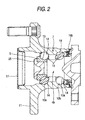
- FIG. 2 shows a second example of the wheel supporting rolling bearing unit as the subject of the present invention.
- the inner ring 5 is fixed by the nut 6 that is screwed onto the outer end portion of the supporting shaft 4a.
- the inner ring 5 is fixed to the supporting shaft 4a by pressing the outer end surface of the inner ring 5 with the caulking portion 25 that is formed by elastically deforming an outer end surface of a supporting shaft 4b as a main shaft member outward in the diameter direction.
- the axial load to apply the preload is adjusted by a load applied when the caulking portion 25 is worked. Structures and operations of other portions are similar to the first example.
- FIG. 3 shows a third example of the wheel supporting rolling bearing unit as the subject of the present invention.
- the structure shown in above FIG. 12 is varied into a structure to which the present invention can be applied.
- an opening portion of the inner end of the outer ring 19 is closed by a cap 17a as a sealing member, and also the inner peripheral surface of the outer end portion of the outer ring 19 and the outer peripheral surface of the middle portion of the hub main body 22 are isolated from each other by the seal ring 16c.
- the cap 17a is fitted/fixed into the opening portion on the inner end of the outer ring 19 as a tight fit.
- a clearance is formed between the cap 17a and the caulking portion 25 that is formed on the inner end portion of the hub 7a as the main shaft member, and thus the cap 17a in no ways slidingly comes into contact with the hub 7a when the hub 7a is rotated.
- the seal ring 16d (FIG.12) between the inner peripheral surface of the inner end portion of the outer ring 19 and the outer peripheral surface of the inner ring 23 is removed. Then, the running resistance of the seal ring 16c is regulated into a range of 0.03 to 0.2 N ⁇ m. The entering of the foreign matter such as muddy water, or the like into the spaces in which the balls 14, 14 are provided is prevented by the seal ring 16c and the cap 17a.
- the axial load to apply the preload is adjusted by a load applied when the caulking portion 25 is worked.
- Structures and operations of other portions are similar to the first example. Structures of other portions are similar to the above structures in first and second examples and the above conventional structure shown in FIG.12.
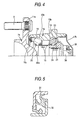
- FIG. 4 shows a fourth example of the wheel supporting rolling bearing unit as the subject of the present invention.
- an inner end surface of the inner ring 23 that is fitted onto the small-diameter stepped portion 24 of a hub main body 22a is pressed by a nut 30 that is screwed onto an external thread portion 39 provided to the inner end portion of the hub main body 22a as the main shaft member.
- a shape of a cap 17b deposited onto the opening portion of the inner end of the outer ring 19 is expanded to meet this arrangement, so that an interference between the external thread portion 39 and the nut 30 is prevented.
- the cap 17b by no means slidingly comes into contact with the external thread portion 39 and the nut 30 when the hub main body 22a is rotated.
- the axial load to apply the preload is adjusted by a torque applied when the nut 30 is tightened. Structures of other portions are similar to the second example.
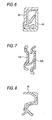
- FIGS. 5 to 9 show a structure that can be utilized as the inside seal ring 16b in the first and second examples of the wheel supporting rolling bearing unit shown in FIGS.1 and 2 respectively.
- FIG.5 a first example shown in FIG.5 is a combinational seal ring in which an outer diameter-side seal ring 31 that is fitted/fixed into the inner end portion of the hub 7 (FIGS. 1 and 2) and an inner diameter-side seal ring 32 that is fitted/fixed onto the portion located near the inner ends of the supporting shafts 4a (FIG.1), 4b (FIG.2) are combined with each other.
- This seal ring has three seal lips in total, i.e., two on the inner diameter side and one on the outer diameter side.
- the torque (running resistance) required for the relative rotation between the outer diameter-side and inner diameter-side seal rings 31, 32 was 0.22 N ⁇ m or more.
- the torque (running resistance) required for the relative rotation between the outer diameter-side and inner diameter-side seal rings 31, 32 based on the friction between top end edges of three seal lips and counter surfaces (surface of the core bar) is regulated in a range of 0.03 to 0.2 N ⁇ m by the method described later, for example.
- FIG.6 a second example shown in FIG.6 is a combinational seal ring in which a seal ring 33 that is fitted/fixed into the inner end portion of the hub 7 (FIGS.1 and 2) and a slinger 34 that is fitted/fixed onto the portion located near the inner ends of the supporting shafts 4a (FIG.1), 4b (FIG.2) are combined with each other.
- the seal ring 33 has three seal lips.
- the torque (running resistance) required for the relative rotation between the seal ring 33 and the slinger 34 based on the friction between top end edges of these three seal lips and the surface of the slinger 34 is regulated in a range of 0.03 to 0.2 N ⁇ m by the method described later, for example.
- FIG.7 a third example shown in FIG.7 is a combinational seal ring in which a seal ring 35a that engages with the inner peripheral surface of the inner end portion of the hub 7 (FIGS.1 and 2) and a seal ring 35b that engages with the outer peripheral surface of the portion located near the inner ends of the supporting shafts 4a (FIG.1), 4b (FIG.2) are combined with each other.
- this seal ring has three seal lips in total, i.e., two on the seal ring 35a engaging with the hub 7 side and one on the seal ring 35b engaging with the supporting shafts 4a, 4b side.
- the torque (running resistance) required for the relative rotation between the hub 7 and the supporting shafts 4a, 4b based on the friction between top end edges of these three seal lips and counter surfaces is regulated in a range of 0.03 to 0.2 N ⁇ m.
- top end edges of two seal lips provided to a seal ring 36 that is fitted into the inner end portion of the hub 7 come into contact with the outer peripheral surface of the portion located near the inner ends of the supporting shafts 4a (FIG.1), 4b (FIG.2).
- the torque (running resistance) required for the relative rotation between the seal ring 36 and the supporting shaft 4a based on the friction between top end edges of two seal lips and the outer peripheral surface of the inner end portions of the supporting shafts 4a, 4b is regulated in a range of 0.03 to 0.2 N ⁇ m.
- a seal ring 37 shown in FIG.9 shows a structure that can be utilized as the inside seal ring in FIG.2, and also can be utilized as a seal ring that is provided between the inner peripheral surface of the outer end portion of the outer ring 19 (FIGS.3 and 4) and the outer peripheral surface of the middle portion of the hub main bodies 22 (FIG.3), 22a (FIG.4) in the wheel supporting rolling bearing unit shown in FIGS.3 and 4 in the third and fourth examples.
- the torque (running resistance) required for the relative rotation between the seal ring 37 and the surfaces of the hub main bodies 22, 22a based on the friction between top end edges of three seal lips and the surfaces of the hub main bodies 22, 22a is regulated in a range of 0.03 to 0.2 N ⁇ m.
- a thickness of a seal lip 38b of three seal lips 38a, 38b, 38c is reduced gradually from the base end portion toward the middle portion and then is increased from the middle portion toward the top end portion. Also, a thickness of the seal lip 38b is maximized at a part of the portion located near the top end.
- the shape is decided to satisfy 0.80d 1 ⁇ d 2 ⁇ 0.98d 1 and 0.1S 2 ⁇ S 1 ⁇ 0.5S 2
- d 1 is a thickness of the base end portion of the seal lip 38b
- d 2 is a thickness of a minimum thickness portion in which a thickness is minimized in the middle portion
- S 1 is a sectional area of a portion extended from the base end portion to the minimum thickness portion in the axial direction
- S 2 is an area of a portion extended from the minimum thickness portion to the top end edge.
- a mark “ ⁇ ” indicates the fact that a large amount of muddy water entered into the internal space in which the grease is sealed
- a mark “ ⁇ ” indicates the fact that a small amount of muddy water entered into the same
- a mark “ ⁇ ” indicates the fact that the entering of the muddy water was not observed. It is appreciated based on such experimental results that, if the seal torque is in excess of 0.03 N ⁇ m, the entering of the muddy water can be prevented by all seal rings.
- Table 2 gives results of second Experiment that was executed to know the influence of the seal torque upon the running torque of the overall rolling bearing unit and the durability. This Experiment was executed at a rotational speed of 200 min -1 .
- Seal torque[N ⁇ m] Evaluation 0 ⁇ ⁇ ⁇ 0.01 ⁇ ⁇ ⁇ 0.03 ⁇ ⁇ ⁇ 0.06 ⁇ ⁇ ⁇ 0.10 ⁇ ⁇ ⁇ 0.15 ⁇ ⁇ ⁇ 0.20 ⁇ ⁇ ⁇ 0.33 ⁇ ⁇ ⁇ 0.45 ⁇ ⁇ ⁇
- Table 4 gives results of fourth Experiment that was executed to know the influence of the rolling resistance upon the rigidity of the rolling bearing unit and the durability. This Experiment was executed at a rotational speed of 200 min -1 .
- Rolling Resistance [N ⁇ m] Evaluation 0.10 ⁇ ⁇ ⁇ 0.12 ⁇ ⁇ ⁇ 0.15 ⁇ ⁇ ⁇ 0.25 ⁇ ⁇ ⁇ 0.35 ⁇ ⁇ ⁇ 0.45 ⁇ ⁇ ⁇ 0.55 ⁇ ⁇ ⁇ 0.65 ⁇ ⁇ ⁇
- Table 6 gives results of Experiment that was executed to know the influences of the seal torque and the rolling resistance upon the running torque of the rolling bearing unit as a whole. This Experiment was executed at a rotational speed of 200 min -1 .
- a mark " ⁇ ” indicates the fact that the running torque was large as a whole
- a mark “ ⁇ ” indicates the fact that the running torque was slightly large
- a mark “ ⁇ ” indicates the fact that the running torque was small.
- the present invention in which both the seal torque and the rolling resistance are suppressed to 0.2 N ⁇ m or less and 0.45 N ⁇ m or less respectively could suppress as a whole the running torque low such as 0.65 N ⁇ m or less.
- the ball diameter denotes a diameter of the ball
- the PCD denotes a pitch diameter of a ball sequence of these balls
- the inter-row distance denotes a pitch (center distance between the balls) of the ball sequences arranges in double rows in the axial direction
- the contact angle denotes a contact angle between the balls and the inner ring raceway and the outer ring raceway.
- Patent Application No.2002-261195 filed on September 6, 2002 and the contents thereof are incorporated herein by the reference.
- the wheel supporting rolling bearing unit of the present invention is constructed and acts as described above, such bearing unit can contribute to the improvement in the running performances of the vehicle, mainly the controllability, the acceleration performance, and the fuel consumption performance, by reducing the running torque of the hub, which rotates together with the wheel, while assuring the rigidity and the durability.
- the running resistance of the wheel supporting rolling bearing unit having the above structure shown in FIGS.1 to 4 was almost 1 N ⁇ m in the prior art.
- the running resistance of the wheel supporting rolling bearing unit of the present invention is in a range of 0.18 to 0.65 N ⁇ m. That is, the running resistance is lowered by 35 % or more rather than the prior art. It is considered that, if the running resistance of the wheel supporting rolling bearing unit is lowered by 10 %, the fuel consumption (fuel consumption ratio) can be improved by about 0.1 %.
- the fuel consumption of which is about 10 km/L travels 100,000 km a year
- the fuel can be saved by about 35 to 82 L a year by employing the wheel supporting rolling bearing unit of the present invention.
- 1,000,000 cars travel in this country, the fuel that can be saved a year reaches 35,000,000 L to 82,000,000 L.
- the industrial usability is extremely high because the fuel consumption can be improved not to cause other disadvantages.
Landscapes
- Engineering & Computer Science (AREA)
- Mechanical Engineering (AREA)
- General Engineering & Computer Science (AREA)
- Rolling Contact Bearings (AREA)
Applications Claiming Priority (3)
| Application Number | Priority Date | Filing Date | Title |
|---|---|---|---|
| JP2002261195 | 2002-09-06 | ||
| JP2002261195 | 2002-09-06 | ||
| PCT/JP2003/011111 WO2004022991A1 (ja) | 2002-09-06 | 2003-08-29 | 車輪支持用転がり軸受ユニット |
Publications (2)
| Publication Number | Publication Date |
|---|---|
| EP1548306A1 true EP1548306A1 (de) | 2005-06-29 |
| EP1548306A4 EP1548306A4 (de) | 2007-07-04 |
Family
ID=31973119
Family Applications (1)
| Application Number | Title | Priority Date | Filing Date |
|---|---|---|---|
| EP03794150A Ceased EP1548306A4 (de) | 2002-09-06 | 2003-08-29 | Wälzlagereinheit für stützrad |
Country Status (7)
| Country | Link |
|---|---|
| US (1) | US7287909B2 (de) |
| EP (1) | EP1548306A4 (de) |
| JP (1) | JPWO2004022991A1 (de) |
| KR (1) | KR100642589B1 (de) |
| CN (1) | CN1678836B (de) |
| AU (1) | AU2003264359A1 (de) |
| WO (1) | WO2004022991A1 (de) |
Cited By (1)
| Publication number | Priority date | Publication date | Assignee | Title |
|---|---|---|---|---|
| WO2010059355A1 (en) * | 2008-10-30 | 2010-05-27 | The Timken Company | Endcap for wheel bearing assembly |
Families Citing this family (12)
| Publication number | Priority date | Publication date | Assignee | Title |
|---|---|---|---|---|
| JP4947963B2 (ja) * | 2005-12-05 | 2012-06-06 | Ntn株式会社 | 車輪用軸受装置およびその製造方法 |
| CN101400979B (zh) * | 2006-03-10 | 2010-12-08 | 日本精工株式会社 | 双列滚动轴承单元用预负荷测量装置 |
| US8845203B2 (en) * | 2008-11-06 | 2014-09-30 | Kyklos Bearing International, Inc. | Wheel bearing assembly |
| JP5338546B2 (ja) * | 2009-07-30 | 2013-11-13 | 日本精工株式会社 | 軸受装置 |
| ITTO20101005A1 (it) * | 2010-12-16 | 2012-06-17 | Skf Ab | Gruppo cuscinetto-mozzo per la ruota di un veicolo a motore |
| CN103415604A (zh) * | 2011-02-18 | 2013-11-27 | 大丰工业株式会社 | 滑动材料组合物和滑动部件 |
| JP5820842B2 (ja) * | 2013-05-08 | 2015-11-24 | 富士重工業株式会社 | 車輪反力検出装置 |
| WO2017076402A1 (de) * | 2015-11-02 | 2017-05-11 | Schaeffler Technologies AG & Co. KG | Radlagereinheit |
| US10087985B2 (en) * | 2016-09-29 | 2018-10-02 | Jtekt Corporation | Rolling device for vehicle |
| IT201900000247A1 (it) * | 2019-01-09 | 2020-07-09 | Skf Ab | Gruppo mozzo-ruota per veicoli |
| IT201900015647A1 (it) * | 2019-09-05 | 2021-03-05 | Skf Ab | Dispositivo di tenuta per gruppo mozzo-ruota |
| CN113237766B (zh) * | 2021-04-22 | 2023-02-24 | 天津大学 | 一种可同时加载多种载荷的管道压力舱加载系统 |
Family Cites Families (14)
| Publication number | Priority date | Publication date | Assignee | Title |
|---|---|---|---|---|
| JPH08319379A (ja) | 1995-02-22 | 1996-12-03 | Uchiyama Mfg Corp | 低摩擦ゴム組成物 |
| JPH09287619A (ja) * | 1996-02-23 | 1997-11-04 | Nippon Seiko Kk | 密封装置付転がり軸受ユニット |
| JPH10252762A (ja) | 1997-03-12 | 1998-09-22 | Nippon Seiko Kk | 転がり軸受用密封装置 |
| JP2000198304A (ja) * | 1998-10-29 | 2000-07-18 | Nsk Ltd | 車輪用転がり軸受ユニット |
| DE60022833T2 (de) * | 1999-07-19 | 2006-03-23 | Nsk Ltd. | Kugellager |
| JP4507394B2 (ja) | 1999-12-20 | 2010-07-21 | 日本精工株式会社 | 車輪支持用転がり軸受ユニットの製造方法 |
| JP2001221243A (ja) | 2000-02-09 | 2001-08-17 | Nsk Ltd | 車輪支持用転がり軸受ユニット |
| US6568856B2 (en) * | 2000-12-04 | 2003-05-27 | Nsk Ltd. | Rolling bearing |
| JP2002227858A (ja) * | 2001-01-31 | 2002-08-14 | Koyo Seiko Co Ltd | 車軸用軸受の密封装置 |
| JP2002323056A (ja) | 2001-04-24 | 2002-11-08 | Ntn Corp | 車輪軸受装置 |
| JP4055398B2 (ja) | 2001-11-08 | 2008-03-05 | 株式会社ジェイテクト | 車輪用転がり軸受装置 |
| AU2003211487A1 (en) | 2002-02-19 | 2003-09-09 | Nsk Ltd. | Rolling bearing unit for supporting wheel |
| JP2005299684A (ja) | 2002-02-25 | 2005-10-27 | Nsk Ltd | 車輪支持用転がり軸受ユニット |
| JP2003269617A (ja) | 2002-03-15 | 2003-09-25 | Nsk Ltd | 密封装置とこれを組み込んだ転がり軸受及びハブユニット |
-
2003
- 2003-08-29 KR KR1020057003794A patent/KR100642589B1/ko not_active Expired - Fee Related
- 2003-08-29 US US10/526,548 patent/US7287909B2/en not_active Expired - Fee Related
- 2003-08-29 JP JP2004534124A patent/JPWO2004022991A1/ja active Pending
- 2003-08-29 CN CN038209942A patent/CN1678836B/zh not_active Expired - Fee Related
- 2003-08-29 EP EP03794150A patent/EP1548306A4/de not_active Ceased
- 2003-08-29 AU AU2003264359A patent/AU2003264359A1/en not_active Abandoned
- 2003-08-29 WO PCT/JP2003/011111 patent/WO2004022991A1/ja not_active Ceased
Cited By (1)
| Publication number | Priority date | Publication date | Assignee | Title |
|---|---|---|---|---|
| WO2010059355A1 (en) * | 2008-10-30 | 2010-05-27 | The Timken Company | Endcap for wheel bearing assembly |
Also Published As
| Publication number | Publication date |
|---|---|
| CN1678836B (zh) | 2010-04-28 |
| US20060165330A1 (en) | 2006-07-27 |
| KR100642589B1 (ko) | 2006-11-10 |
| CN1678836A (zh) | 2005-10-05 |
| JPWO2004022991A1 (ja) | 2005-12-22 |
| EP1548306A4 (de) | 2007-07-04 |
| KR20050057193A (ko) | 2005-06-16 |
| US7287909B2 (en) | 2007-10-30 |
| WO2004022991A1 (ja) | 2004-03-18 |
| AU2003264359A1 (en) | 2004-03-29 |
Similar Documents
| Publication | Publication Date | Title |
|---|---|---|
| US7338212B2 (en) | Wheel supporting rolling bearing unit | |
| US6280093B1 (en) | Wheel supporting structure | |
| US7287909B2 (en) | Wheel supporting rolling bearing unit | |
| EP2636915A1 (de) | Lagervorrichtung für fahrzeugräder | |
| US10752049B2 (en) | Wheel bearing device | |
| CN101675259A (zh) | 车轮用轴承及具有该车轮用轴承的车轮用轴承装置 | |
| JP2003222145A (ja) | シールリング付車輪支持用転がり軸受ユニット | |
| US7246946B2 (en) | Rolling bearing unit for supporting wheel | |
| US20220065290A1 (en) | Method for manufacturing bearing device for vehicle wheel, and bearing device for vehicle wheel | |
| JP2005299685A (ja) | 車輪支持用転がり軸受ユニット | |
| EP1489320A1 (de) | Wälzlagereinheit zum abstützen eines rads | |
| US20080304784A1 (en) | Rolling Bearing Assembly | |
| JPH1151064A (ja) | ハブユニット軸受 | |
| JP2003239999A (ja) | 車輪支持用転がり軸受ユニット | |
| JP2005299684A (ja) | 車輪支持用転がり軸受ユニット | |
| JP2019019893A (ja) | 後輪用ハブユニット軸受 | |
| JP2003097567A (ja) | 車軸用軸受装置 | |
| JP2003021151A (ja) | 車輪用軸受装置 | |
| JP2023159713A (ja) | ハブユニット軸受 | |
| JP2022126993A (ja) | ハブユニット軸受 | |
| JP2000158905A (ja) | ホイール用軸受 | |
| JP2023137217A (ja) | アンギュラ玉軸受用保持器及びアンギュラ玉軸受 | |
| JP2013019427A (ja) | 軸受ユニット | |
| JP2008101682A (ja) | 車輪用軸受装置 |
Legal Events
| Date | Code | Title | Description |
|---|---|---|---|
| PUAI | Public reference made under article 153(3) epc to a published international application that has entered the european phase |
Free format text: ORIGINAL CODE: 0009012 |
|
| 17P | Request for examination filed |
Effective date: 20050303 |
|
| AK | Designated contracting states |
Kind code of ref document: A1 Designated state(s): AT BE BG CH CY CZ DE DK EE ES FI FR GB GR HU IE IT LI LU MC NL PT RO SE SI SK TR |
|
| AX | Request for extension of the european patent |
Extension state: AL LT LV MK |
|
| DAX | Request for extension of the european patent (deleted) | ||
| RBV | Designated contracting states (corrected) |
Designated state(s): DE GB |
|
| A4 | Supplementary search report drawn up and despatched |
Effective date: 20070606 |
|
| RIC1 | Information provided on ipc code assigned before grant |
Ipc: F16C 43/04 20060101ALI20070531BHEP Ipc: F16C 35/06 20060101ALI20070531BHEP Ipc: B60B 27/00 20060101ALI20070531BHEP Ipc: F16C 25/06 20060101ALI20070531BHEP Ipc: F16C 19/18 20060101ALI20070531BHEP Ipc: F16C 33/78 20060101AFI20040324BHEP |
|
| 17Q | First examination report despatched |
Effective date: 20070828 |
|
| STAA | Information on the status of an ep patent application or granted ep patent |
Free format text: STATUS: THE APPLICATION HAS BEEN REFUSED |
|
| 18R | Application refused |
Effective date: 20090510 |