EP1548272A1 - Ventilkörper für einen Flüssigkeitsinjektor - Google Patents
Ventilkörper für einen Flüssigkeitsinjektor Download PDFInfo
- Publication number
- EP1548272A1 EP1548272A1 EP03029639A EP03029639A EP1548272A1 EP 1548272 A1 EP1548272 A1 EP 1548272A1 EP 03029639 A EP03029639 A EP 03029639A EP 03029639 A EP03029639 A EP 03029639A EP 1548272 A1 EP1548272 A1 EP 1548272A1
- Authority
- EP
- European Patent Office
- Prior art keywords
- zone
- valve body
- needle
- guided
- guide zone
- Prior art date
- Legal status (The legal status is an assumption and is not a legal conclusion. Google has not performed a legal analysis and makes no representation as to the accuracy of the status listed.)
- Granted
Links
Images


Classifications
-
- F—MECHANICAL ENGINEERING; LIGHTING; HEATING; WEAPONS; BLASTING
- F02—COMBUSTION ENGINES; HOT-GAS OR COMBUSTION-PRODUCT ENGINE PLANTS
- F02M—SUPPLYING COMBUSTION ENGINES IN GENERAL WITH COMBUSTIBLE MIXTURES OR CONSTITUENTS THEREOF
- F02M61/00—Fuel-injectors not provided for in groups F02M39/00 - F02M57/00 or F02M67/00
- F02M61/16—Details not provided for in, or of interest apart from, the apparatus of groups F02M61/02 - F02M61/14
- F02M61/167—Means for compensating clearance or thermal expansion
-
- F—MECHANICAL ENGINEERING; LIGHTING; HEATING; WEAPONS; BLASTING
- F02—COMBUSTION ENGINES; HOT-GAS OR COMBUSTION-PRODUCT ENGINE PLANTS
- F02M—SUPPLYING COMBUSTION ENGINES IN GENERAL WITH COMBUSTIBLE MIXTURES OR CONSTITUENTS THEREOF
- F02M51/00—Fuel-injection apparatus characterised by being operated electrically
- F02M51/06—Injectors peculiar thereto with means directly operating the valve needle
- F02M51/0603—Injectors peculiar thereto with means directly operating the valve needle using piezoelectric or magnetostrictive operating means
-
- F—MECHANICAL ENGINEERING; LIGHTING; HEATING; WEAPONS; BLASTING
- F02—COMBUSTION ENGINES; HOT-GAS OR COMBUSTION-PRODUCT ENGINE PLANTS
- F02M—SUPPLYING COMBUSTION ENGINES IN GENERAL WITH COMBUSTIBLE MIXTURES OR CONSTITUENTS THEREOF
- F02M61/00—Fuel-injectors not provided for in groups F02M39/00 - F02M57/00 or F02M67/00
- F02M61/04—Fuel-injectors not provided for in groups F02M39/00 - F02M57/00 or F02M67/00 having valves, e.g. having a plurality of valves in series
- F02M61/08—Fuel-injectors not provided for in groups F02M39/00 - F02M57/00 or F02M67/00 having valves, e.g. having a plurality of valves in series the valves opening in direction of fuel flow
-
- F—MECHANICAL ENGINEERING; LIGHTING; HEATING; WEAPONS; BLASTING
- F02—COMBUSTION ENGINES; HOT-GAS OR COMBUSTION-PRODUCT ENGINE PLANTS
- F02M—SUPPLYING COMBUSTION ENGINES IN GENERAL WITH COMBUSTIBLE MIXTURES OR CONSTITUENTS THEREOF
- F02M61/00—Fuel-injectors not provided for in groups F02M39/00 - F02M57/00 or F02M67/00
- F02M61/04—Fuel-injectors not provided for in groups F02M39/00 - F02M57/00 or F02M67/00 having valves, e.g. having a plurality of valves in series
- F02M61/10—Other injectors with elongated valve bodies, i.e. of needle-valve type
- F02M61/12—Other injectors with elongated valve bodies, i.e. of needle-valve type characterised by the provision of guiding or centring means for valve bodies
Definitions
- the invention relates to a valve body with a needle, which closes or opens a nozzle depending on its position and comprises a guided zone.
- the invention further relates to a fluid injector with an actuating unit, a housing and the valve body.
- Fluid injectors in particular fuel injectors for diesel or gasoline internal combustion engines, comprise a housing, an actuator unit and a valve body.
- the valve body comprises a needle that opens or closes a nozzle and in that way controls the injection of fuel.
- actuator units with a piezoelectric actuator are used. They have the advantage of having a very fast response time to actuating signals and enable like that multiple injections into a cylinder of the internal combustion engine during one working cycle of the cylinder.
- the fluid pressure is increased.
- the fluid injectors are supplied with fuel which has a pressure of up to 200 bars.
- WO 03/016707 A1 discloses a fluid injector with a connector to a fuel supply, a housing, an actuator unit, and a valve body.
- the housing is double tubed and has a recess, which takes up the actuator unit.
- the actuator unit comprises a piezoelectric actuator, which acts on the needle.
- Between the walls of the double tube-shaped housing the fuel is led from the connector to a fuel inlet of the valve body.
- the valve body has a housing part with a recess, that takes up a needle. Depending on the position of the needle a nozzle is opened or closed and respectively fuel is injected or not. In order to ensure a reliable operation of the valve body and the fluid injector the needle needs to be reliably guided in the valve body.
- the object of the invention is to create a valve body and a fluid injector with a valve body, which ensures a reliable guidance of a needle in the valve body.
- the invention is distinguished by a valve body with a needle, which closes or opens a nozzle depending on its position and comprises a guided zone.
- the valve body further comprises a first part, which is arranged in a fixed position relative to the nozzle and comprises a guided zone. It further comprises a second part, which comprises a first guide zone, that guides the guided zone of the needle, and which comprises a second guide zone, that guides the guided zone of the first part, with the second guide zone having a greater diameter than the first guide zone.
- This has the advantage, that the guided zone of the needle can be spaced far away from the nozzle, which gives freedom for the construction of the area closer to the nozzle.
- the second guide zone of the second part and the guided zone may be short in axial extension. The greater the diameter of the second guide zone is the shorter may be its axial extension without decrease in the quality in the guidance of the needle.
- the second part is during operation of the valve body in a fixed relative position to the needle.
- the invention is further distinguished by a valve body with a needle which closes or opens a nozzle depending on its position and comprises a guided zone, a first part, which is arranged in a fixed position relative to the nozzle and comprises a guide zone.
- the valve body further comprises a second part, which comprises a first guide zone that guides the guided zone of the needle and which comprises a guided zone, that is guided by the guide zone of the first part, whith the guide zone of the first part having a greater diameter than the first guide zone.
- This also has the advantage that the guided zone of the needle can be spaced far away from the nozzle which then gives additional freedom for the construction of the area closer to the nozzle.
- the guide zone of the first part and the guided zone of the second part may be short in axial extension. The greater the diameter of the guided zone of the first part is, the shorter may be its axial extension without a decrease in the quality of the guidance of the needle.
- the second guide zone of the second part or respectively the guide zone of the first part have a smaller diameter than a free diameter of a return spring, that is arranged axially outwards from the second guide zone or respectively the guide zone of the first part.
- the second part comprises a spring rest, where a return spring rests.
- the guided zone of the needle and the first guide zone of the second part are located before a fluid inlet towards the needle in the direction of the nozzle.
- the first guide zone is axially spaced to the second guide zone or respectively to the guided zone of the first part.
- the first guide zone is axially further spaced apart from the nozzle then the second guide zone and respectively the guided zone of the second part.
- the first part forms the nozzle and takes in the needle.
- the invention is further distinguished by a fluid injector with a housing, an actuator unit and a valve body.
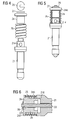
- a fluid injector which in this embodiment is a fuel injector ( Figure 1) of an internal combustion engine, is designed to be connected to a fuel supply via a fuel connector 4.
- the fuel supply preferably comprises a high pressure chamber, where fuel is stored under a pressure of up to 200 Bar.
- the fuel injector comprises a housing 1, a valve body 2, an actuator unit 3 and a fuel connector 4.
- the housing 1 is formed in a double tubed manner. Between the walls of the double tubed housing 1 the fuel is led from the fuel connector 4 to the valve body 2. By this the fuel can be led to the valve body 2 in a substantially unthrottled way.
- the valve body 2 is connected to a free end of the housing 1, preferably by welding.
- the valve body 2 comprises a needle 22, that is taken up in a recess 211 of the valve body 2 and which closes or opens a nozzle 213 depending on its position in the valve body 2 and in this way controls the fuel injection into a cylinder of the internal combustion engine.
- a return spring 25 pushes the needle 22 in the position, where the nozzle 213 is closed.
- the needle 22 is of an outward opening type, but it may also be of an inward opening type.
- the return spring 25 exerts a force on the needle 22 in the closing direction of the needle 22.
- the needle 22 is coupled to the actuator unit 3.
- the actuator unit 3 changes its axial length and by that pushes the needle 22 in its open position or leaves it in its closed position.
- the actuator unit 3 comprises a piezo actuator that is inserted in a tube spring, which pretensions the piezo actuator with a given force.
- a thermal compensator may be coupled with the actuator unit 3 and the housing 1 in order to compensate different thermal lengthening coefficients of the housing 1 and the actuator unit 3.
- the valve body 2 comprises a first part 21, a second part 24, the return spring 25 and the needle 22.
- the first part 21 has the recess 211, into which the needle 22 is inserted and which at one of its ends forms the nozzle 213.
- the fuel is led from a fuel inlet 214 to the nozzle 213 in the space between the needle 22 and the walls of the recess 211 of the first part 21.
- the second part 24 has a spring rest 244, where a return spring 25 rests.
- a spring retainer 26 limits the axial movement of the second part 24 in the direction of the actuator unit 3.
- the second part further comprises a recess 241 in which a first guide zone 242 is formed, that guides the needle 22 in the guided zone 221 of the needle 22.
- the second part 24 further comprises a second guide 243, which guides the first part 21 in a guided zone 215.
- the first and second guide zone 242, 243 are formed coaxially and the diameter of the second guide zone 243 is greater than the diameter of the first guide zone 242.
- the first part 21 stays in its position and the second part makes an axial movement corresponding to the axial movement of the needle 22. In this way there is a sliding movement between the first and the second part 21, 24 in the area of the second guide zone 243 and the guided zone 215 of the first part 21.
- the quality of the guidance is influenced essentially by the size of this surface.
- the first guide zone 242 and the guided zone 221 of the needle 22 acting together with the second guide zone 243 and the guided zone 215 of the first part 21 have the effect, that even if the guided zone 221 of the needle 22 is located far away from the nozzle 213 the needle 22 is reliably guided without creating relevant oscillations of the needle in the radial direction. If the guided zone 221 of the needle and the first guide zone 242 of the second part are located before the fluid inlet 214 towards the needle 22 in the direction of the nozzle 213, there is no need for another guided zone of the needle in the area, where the fuel flows between the needle 22 and the wall of the recess of the first part 21.
- a calibrated shim 27 ( Figure 4) or more than one calibrated shim 27 are pushed on the needle between the retainer 26 and the spring rest 244 in order to precisely pretension the return spring 25.
- valve body 2 there is a guided zone 245 on the second part 24 that acts together with a guide zone 216 of the first part 21.
- first guide zone 221 of the second part 24 and the guided zone 242 on the needle 22 act together with the guided zone 245 of the second part 24 and the guide zone 216 of the first part 21.
- a reliable guidance of the needle 22 is ensured even if the guided zone 242 of the needle 25 is located relatively far away from the nozzle 213.
Landscapes
- Engineering & Computer Science (AREA)
- Chemical & Material Sciences (AREA)
- Combustion & Propulsion (AREA)
- Mechanical Engineering (AREA)
- General Engineering & Computer Science (AREA)
- Fuel-Injection Apparatus (AREA)
Priority Applications (6)
| Application Number | Priority Date | Filing Date | Title |
|---|---|---|---|
| EP03029639A EP1548272B1 (de) | 2003-12-22 | 2003-12-22 | Ventilkörper für einen Flüssigkeitsinjektor |
| DE60307117T DE60307117T2 (de) | 2003-12-22 | 2003-12-22 | Ventilkörper für einen Flüssigkeitsinjektor |
| US10/596,689 US7575183B2 (en) | 2003-12-22 | 2004-12-08 | Valve body and fluid injector with valve body |
| JP2006546152A JP2007516382A (ja) | 2003-12-22 | 2004-12-08 | 弁体及び弁体を備えた流体インジェクタ |
| CNA2004800384294A CN1898466A (zh) | 2003-12-22 | 2004-12-08 | 阀主体和具有阀主体的流体喷射器 |
| PCT/EP2004/053354 WO2005061885A1 (en) | 2003-12-22 | 2004-12-08 | Valve body and fluid injector with valve body |
Applications Claiming Priority (1)
| Application Number | Priority Date | Filing Date | Title |
|---|---|---|---|
| EP03029639A EP1548272B1 (de) | 2003-12-22 | 2003-12-22 | Ventilkörper für einen Flüssigkeitsinjektor |
Publications (2)
| Publication Number | Publication Date |
|---|---|
| EP1548272A1 true EP1548272A1 (de) | 2005-06-29 |
| EP1548272B1 EP1548272B1 (de) | 2006-07-26 |
Family
ID=34530706
Family Applications (1)
| Application Number | Title | Priority Date | Filing Date |
|---|---|---|---|
| EP03029639A Expired - Lifetime EP1548272B1 (de) | 2003-12-22 | 2003-12-22 | Ventilkörper für einen Flüssigkeitsinjektor |
Country Status (6)
| Country | Link |
|---|---|
| US (1) | US7575183B2 (de) |
| EP (1) | EP1548272B1 (de) |
| JP (1) | JP2007516382A (de) |
| CN (1) | CN1898466A (de) |
| DE (1) | DE60307117T2 (de) |
| WO (1) | WO2005061885A1 (de) |
Families Citing this family (5)
| Publication number | Priority date | Publication date | Assignee | Title |
|---|---|---|---|---|
| NO328410B1 (no) | 2008-06-27 | 2010-02-15 | Hydra Tidal Energy Technology | System for forankring av et flytende anlegg for produksjon av energi fra strommer i en vannmasse |
| JP2011185264A (ja) * | 2010-02-11 | 2011-09-22 | Denso Corp | インジェクタ |
| DE102012207842A1 (de) * | 2012-05-10 | 2013-11-14 | Continental Automotive Gmbh | Einspritzventil |
| CN103670859B (zh) * | 2012-09-12 | 2016-08-03 | 北京亚新科天纬油泵油嘴股份有限公司 | 喷射器的喷射嘴 |
| JP6186126B2 (ja) * | 2013-01-24 | 2017-08-23 | 日立オートモティブシステムズ株式会社 | 燃料噴射装置 |
Citations (3)
| Publication number | Priority date | Publication date | Assignee | Title |
|---|---|---|---|---|
| DE483126C (de) * | 1927-08-30 | 1929-09-26 | Deckel Friedrich | Einspritzduese fuer Verbrennungskraftmaschinen, insbesondere mit luftloser Einspritzung |
| GB2112455A (en) * | 1981-12-24 | 1983-07-20 | Lucas Ind Plc | Guiding outwardly opening valves in fuel injectors |
| EP0967386A2 (de) * | 1998-05-29 | 1999-12-29 | LUCAS INDUSTRIES public limited company | Kraftstoffeinspritzventil |
Family Cites Families (6)
| Publication number | Priority date | Publication date | Assignee | Title |
|---|---|---|---|---|
| DE2720144A1 (de) * | 1977-05-05 | 1978-11-16 | Volkswagenwerk Ag | Einspritzvorrichtung, insbesondere fuer eine brennkraftmaschine |
| US5494223A (en) * | 1994-08-18 | 1996-02-27 | Siemens Automotive L.P. | Fuel injector having improved parallelism of impacting armature surface to impacted stop surface |
| US5544816A (en) * | 1994-08-18 | 1996-08-13 | Siemens Automotive L.P. | Housing for coil of solenoid-operated fuel injector |
| US5647536A (en) * | 1995-01-23 | 1997-07-15 | Cummins Engine Company, Inc. | Injection rate shaping nozzle assembly for a fuel injector |
| GB9525369D0 (en) * | 1995-12-12 | 1996-02-14 | Lucas Ind Plc | Injector |
| WO2003016707A1 (de) | 2001-08-08 | 2003-02-27 | Siemens Aktiengesellschaft | Dosiervorrichtung |
-
2003
- 2003-12-22 EP EP03029639A patent/EP1548272B1/de not_active Expired - Lifetime
- 2003-12-22 DE DE60307117T patent/DE60307117T2/de not_active Expired - Lifetime
-
2004
- 2004-12-08 JP JP2006546152A patent/JP2007516382A/ja active Pending
- 2004-12-08 US US10/596,689 patent/US7575183B2/en not_active Expired - Fee Related
- 2004-12-08 WO PCT/EP2004/053354 patent/WO2005061885A1/en not_active Ceased
- 2004-12-08 CN CNA2004800384294A patent/CN1898466A/zh active Pending
Patent Citations (3)
| Publication number | Priority date | Publication date | Assignee | Title |
|---|---|---|---|---|
| DE483126C (de) * | 1927-08-30 | 1929-09-26 | Deckel Friedrich | Einspritzduese fuer Verbrennungskraftmaschinen, insbesondere mit luftloser Einspritzung |
| GB2112455A (en) * | 1981-12-24 | 1983-07-20 | Lucas Ind Plc | Guiding outwardly opening valves in fuel injectors |
| EP0967386A2 (de) * | 1998-05-29 | 1999-12-29 | LUCAS INDUSTRIES public limited company | Kraftstoffeinspritzventil |
Also Published As
| Publication number | Publication date |
|---|---|
| CN1898466A (zh) | 2007-01-17 |
| WO2005061885A1 (en) | 2005-07-07 |
| EP1548272B1 (de) | 2006-07-26 |
| DE60307117D1 (de) | 2006-09-07 |
| JP2007516382A (ja) | 2007-06-21 |
| DE60307117T2 (de) | 2006-12-21 |
| US7575183B2 (en) | 2009-08-18 |
| US20070290076A1 (en) | 2007-12-20 |
Similar Documents
| Publication | Publication Date | Title |
|---|---|---|
| US7644874B2 (en) | Injector | |
| CN103649519A (zh) | 压电式喷油器 | |
| US8919372B2 (en) | Valve assembly for an injection valve and injection valve | |
| EP1548272B1 (de) | Ventilkörper für einen Flüssigkeitsinjektor | |
| EP1559904A1 (de) | Ventilkörper, Fluidinjektor und Herstellungsmethode für einen Ventilkörper | |
| US8695899B2 (en) | Fuel injector | |
| EP1548854B1 (de) | Aktoreinheit und Verfahren zu deren Herstellung | |
| US10330062B2 (en) | Injector for injecting fluid | |
| JP2008002306A (ja) | 燃料噴射弁 | |
| US8662420B2 (en) | Valve body and fluid injector with a valve body | |
| EP1559905A1 (de) | Einspritzventil mit einem verformbaren Ventilnadel | |
| EP1568881B1 (de) | Flüssigkeitsinjektor | |
| EP1500810A1 (de) | Aktoreinheit | |
| EP1887216B1 (de) | Anordnung zum thermischen Ausgleich in einem Einspritzventil | |
| EP1574705B1 (de) | Flüssigkeitseinspritzventil | |
| US20070241213A1 (en) | Actor Device For An Injector And Injector | |
| EP2080895B1 (de) | Thermische Kompensationsanordnung und Einspritzventil | |
| EP1918571B1 (de) | Injektor zur Dosierung von Flüssigkeit | |
| EP2141346B1 (de) | Thermische Kompensationsanordnung und Einspritzventil | |
| EP2141347A1 (de) | Wärmekompensationsanordnung | |
| EP1689005B1 (de) | Stelleinrichtung und Flüssigkeitseinspritzventil | |
| JP2005248853A (ja) | インジェクタ |
Legal Events
| Date | Code | Title | Description |
|---|---|---|---|
| PUAI | Public reference made under article 153(3) epc to a published international application that has entered the european phase |
Free format text: ORIGINAL CODE: 0009012 |
|
| AK | Designated contracting states |
Kind code of ref document: A1 Designated state(s): AT BE BG CH CY CZ DE DK EE ES FI FR GB GR HU IE IT LI LU MC NL PT RO SE SI SK TR |
|
| AX | Request for extension of the european patent |
Extension state: AL LT LV MK |
|
| GRAP | Despatch of communication of intention to grant a patent |
Free format text: ORIGINAL CODE: EPIDOSNIGR1 |
|
| 17P | Request for examination filed |
Effective date: 20051219 |
|
| AKX | Designation fees paid |
Designated state(s): DE FR GB IT |
|
| GRAS | Grant fee paid |
Free format text: ORIGINAL CODE: EPIDOSNIGR3 |
|
| GRAA | (expected) grant |
Free format text: ORIGINAL CODE: 0009210 |
|
| AK | Designated contracting states |
Kind code of ref document: B1 Designated state(s): DE FR GB IT |
|
| REG | Reference to a national code |
Ref country code: GB Ref legal event code: FG4D |
|
| REF | Corresponds to: |
Ref document number: 60307117 Country of ref document: DE Date of ref document: 20060907 Kind code of ref document: P |
|
| ET | Fr: translation filed | ||
| PLBE | No opposition filed within time limit |
Free format text: ORIGINAL CODE: 0009261 |
|
| STAA | Information on the status of an ep patent application or granted ep patent |
Free format text: STATUS: NO OPPOSITION FILED WITHIN TIME LIMIT |
|
| 26N | No opposition filed |
Effective date: 20070427 |
|
| REG | Reference to a national code |
Ref country code: FR Ref legal event code: CD |
|
| PGFP | Annual fee paid to national office [announced via postgrant information from national office to epo] |
Ref country code: IT Payment date: 20121219 Year of fee payment: 10 Ref country code: GB Payment date: 20121220 Year of fee payment: 10 |
|
| PGFP | Annual fee paid to national office [announced via postgrant information from national office to epo] |
Ref country code: FR Payment date: 20130130 Year of fee payment: 10 Ref country code: DE Payment date: 20121231 Year of fee payment: 10 |
|
| REG | Reference to a national code |
Ref country code: DE Ref legal event code: R119 Ref document number: 60307117 Country of ref document: DE |
|
| GBPC | Gb: european patent ceased through non-payment of renewal fee |
Effective date: 20131222 |
|
| REG | Reference to a national code |
Ref country code: FR Ref legal event code: ST Effective date: 20140829 |
|
| REG | Reference to a national code |
Ref country code: DE Ref legal event code: R119 Ref document number: 60307117 Country of ref document: DE Effective date: 20140701 |
|
| PG25 | Lapsed in a contracting state [announced via postgrant information from national office to epo] |
Ref country code: DE Free format text: LAPSE BECAUSE OF NON-PAYMENT OF DUE FEES Effective date: 20140701 |
|
| PG25 | Lapsed in a contracting state [announced via postgrant information from national office to epo] |
Ref country code: FR Free format text: LAPSE BECAUSE OF NON-PAYMENT OF DUE FEES Effective date: 20131231 Ref country code: GB Free format text: LAPSE BECAUSE OF NON-PAYMENT OF DUE FEES Effective date: 20131222 |
|
| PG25 | Lapsed in a contracting state [announced via postgrant information from national office to epo] |
Ref country code: IT Free format text: LAPSE BECAUSE OF NON-PAYMENT OF DUE FEES Effective date: 20131231 |
|
| PG25 | Lapsed in a contracting state [announced via postgrant information from national office to epo] |
Ref country code: IT Free format text: LAPSE BECAUSE OF NON-PAYMENT OF DUE FEES Effective date: 20131222 |