EP1548230B2 - Aube ayant des entretoises profilées au niveau du bord de fuite - Google Patents
Aube ayant des entretoises profilées au niveau du bord de fuite Download PDFInfo
- Publication number
- EP1548230B2 EP1548230B2 EP04257791.6A EP04257791A EP1548230B2 EP 1548230 B2 EP1548230 B2 EP 1548230B2 EP 04257791 A EP04257791 A EP 04257791A EP 1548230 B2 EP1548230 B2 EP 1548230B2
- Authority
- EP
- European Patent Office
- Prior art keywords
- pedestals
- diameter
- cylindrical
- blade
- set forth
- Prior art date
- Legal status (The legal status is an assumption and is not a legal conclusion. Google has not performed a legal analysis and makes no representation as to the accuracy of the status listed.)
- Expired - Lifetime
Links
- 238000001816 cooling Methods 0.000 claims description 17
- 230000008646 thermal stress Effects 0.000 claims description 6
- 238000002485 combustion reaction Methods 0.000 claims description 3
- 230000035882 stress Effects 0.000 description 9
- NJPPVKZQTLUDBO-UHFFFAOYSA-N novaluron Chemical compound C1=C(Cl)C(OC(F)(F)C(OC(F)(F)F)F)=CC=C1NC(=O)NC(=O)C1=C(F)C=CC=C1F NJPPVKZQTLUDBO-UHFFFAOYSA-N 0.000 description 6
- 239000000446 fuel Substances 0.000 description 2
- 238000000034 method Methods 0.000 description 2
- 238000010248 power generation Methods 0.000 description 2
- WYTGDNHDOZPMIW-RCBQFDQVSA-N alstonine Natural products C1=CC2=C3C=CC=CC3=NC2=C2N1C[C@H]1[C@H](C)OC=C(C(=O)OC)[C@H]1C2 WYTGDNHDOZPMIW-RCBQFDQVSA-N 0.000 description 1
- 238000005266 casting Methods 0.000 description 1
- 239000012530 fluid Substances 0.000 description 1
- 238000004519 manufacturing process Methods 0.000 description 1
- 238000005259 measurement Methods 0.000 description 1
- 239000000203 mixture Substances 0.000 description 1
- 230000003068 static effect Effects 0.000 description 1
Images


Classifications
-
- F—MECHANICAL ENGINEERING; LIGHTING; HEATING; WEAPONS; BLASTING
- F01—MACHINES OR ENGINES IN GENERAL; ENGINE PLANTS IN GENERAL; STEAM ENGINES
- F01D—NON-POSITIVE DISPLACEMENT MACHINES OR ENGINES, e.g. STEAM TURBINES
- F01D5/00—Blades; Blade-carrying members; Heating, heat-insulating, cooling or antivibration means on the blades or the members
- F01D5/12—Blades
- F01D5/14—Form or construction
- F01D5/18—Hollow blades, i.e. blades with cooling or heating channels or cavities; Heating, heat-insulating or cooling means on blades
- F01D5/187—Convection cooling
-
- F—MECHANICAL ENGINEERING; LIGHTING; HEATING; WEAPONS; BLASTING
- F01—MACHINES OR ENGINES IN GENERAL; ENGINE PLANTS IN GENERAL; STEAM ENGINES
- F01D—NON-POSITIVE DISPLACEMENT MACHINES OR ENGINES, e.g. STEAM TURBINES
- F01D5/00—Blades; Blade-carrying members; Heating, heat-insulating, cooling or antivibration means on the blades or the members
- F01D5/12—Blades
- F01D5/14—Form or construction
-
- F—MECHANICAL ENGINEERING; LIGHTING; HEATING; WEAPONS; BLASTING
- F05—INDEXING SCHEMES RELATING TO ENGINES OR PUMPS IN VARIOUS SUBCLASSES OF CLASSES F01-F04
- F05D—INDEXING SCHEME FOR ASPECTS RELATING TO NON-POSITIVE-DISPLACEMENT MACHINES OR ENGINES, GAS-TURBINES OR JET-PROPULSION PLANTS
- F05D2260/00—Function
- F05D2260/20—Heat transfer, e.g. cooling
- F05D2260/221—Improvement of heat transfer
- F05D2260/2212—Improvement of heat transfer by creating turbulence
-
- Y—GENERAL TAGGING OF NEW TECHNOLOGICAL DEVELOPMENTS; GENERAL TAGGING OF CROSS-SECTIONAL TECHNOLOGIES SPANNING OVER SEVERAL SECTIONS OF THE IPC; TECHNICAL SUBJECTS COVERED BY FORMER USPC CROSS-REFERENCE ART COLLECTIONS [XRACs] AND DIGESTS
- Y02—TECHNOLOGIES OR APPLICATIONS FOR MITIGATION OR ADAPTATION AGAINST CLIMATE CHANGE
- Y02T—CLIMATE CHANGE MITIGATION TECHNOLOGIES RELATED TO TRANSPORTATION
- Y02T50/00—Aeronautics or air transport
- Y02T50/60—Efficient propulsion technologies, e.g. for aircraft
Definitions
- This application relates to an airfoil for a turbine blade, wherein pedestals connecting opposed walls in a trailing edge cooling chamber have cross-sections designed to accommodate thermal stress.
- Turbine blades are utilized in gas turbine engines.
- a turbine blade typically includes a platform, with an airfoil shape extending above the platform.
- the airfoil is curved, extending from a leading edge to a trailing edge.
- Cooling channels are formed within the airfoil body to circulate cooling air.
- One type of cooling channel which is used particularly adjacent the trailing edge is an open chamber having cylindrical pedestals connecting opposed suction and pressure side walls. Cooling air flows around these pedestals, and through the open chamber. Typically, the pedestals have had a generally equal diameter.
- the cylindrical pedestals have sometimes been subject to concentrated heat-induced stress.
- the pressure side is much hotter than the suction side, there is more thermal expansion on the pressure side. This is particularly true adjacent the platform. Since the pressure side of the airfoil expands for a greater extent than the suction side, concentrated stresses are applied to the pedestals. This is undesirable.
- the invention is defined in the accompanying claims.
- the elliptical shape creates a larger radius that lowers the stress concentrations.
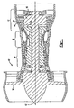
- Figure 1 shows a gas turbine engine 10, such as a gas turbine used for power generation or propulsion, circumferentially disposed about an engine centerline, or axial centerline axis 12.
- the engine 10 includes a fan 14, a compressor 16, a combustion section 18 and a turbine 11.
- air compressed in the compressor 16 is mixed with fuel which is burned in the combustion section 18 and expanded in turbine 11.
- the air compressed in the compressor and the fuel mixture expanded in the turbine 11 can both be referred to as a hot gas stream flow.
- the turbine 11 includes rotors 13 and 15 that, in response to the expansion, rotate, driving the compressor 16 and fan 14.
- the turbine 11 comprises alternating rows of rotary blades 20 and static airfoils or vanes 19.
- Figure 1 is a somewhat schematic representation, for illustrative purposes only, and is not a limitation of the instant invention, that may be employed on gas turbines used for electrical power generation and aircraft.
- Figure 2 shows blade 20 having a platform 22.
- a curved airfoil 24 extends upwardly from the platform 22.
- the airfoil 24 has a leading edge 25 and a trailing edge 23.
- a pressure side 26 contacts a hotter fluid than the suction side 28.
- Cooling passages 35 extend to provide one or more serpentine and straight cooling flow paths through the great bulk of the airfoil 24.
- An open cooling chamber 30 is formed adjacent the trailing edge 23.
- a wall 33 separates passage 35 from chamber 30.
- pedestals 34 and 36 connect the opposed pressure 26 and suction 28 walls.
- the chamber 30 is relatively open allowing flow of cooling air.
- the pedestals are spaced in an array along the length of the airfoil.
- a region 38 is defined having elliptic pedestals 34.
- elliptic pedestals 34 are used particularly around the lower edge of the array and adjacent the platform 22.
- the chamber 30 extends around and past the pedestals 32, 34 and 36. Pedestals 32 and 36 are cylindrical.
- the blade 20 is typically cast from a lost core casting technique.
- the core will initially have openings that form the pedestals 32, 34 and 36.
- Such openings have a flashing that is to be removed.
- a cylindrical opening is easiest to clean, as a simple cylindrical tool might be inserted into the opening.
- the elliptic openings require more work to clean.
- the elliptic pedestals 34 have a major diameter X that is greater than the minor diameter Y.
- the major diameter X is generally parallel to the platform 22.
- a (major diameter) : (minor diameter) ratio of 1.25 to 1.75 is desirable.
- One preferred embodiment has a ratio of approximately 1.5.
- one exemplary pedestal had a major diameter of .090" (2.29 mm), and a minor diameter of .065" (1.65 mm).
- a preferred range of minor diameters is .040" (1.02 mm) to .10" (2.54 mm) with a corresponding preferred range for the major diameters being set by the ratio range (.05" (1.27 mm) to .175" (4.44 mm)).
- the cylindrical pedestals 32, and the remaining pedestals generally above the area 38 all have a first smaller diameter than the cylindrical pedestals 36 that are adjacent the trailing edge.
- the pedestals 32 that are adjacent the leading edge can better withstand the thermal stresses, even adjacent platform 22, in that they tend to be longer than the pedestals spaced closer to the trailing edge.
- the width of the chamber 30 between the discharge side 26 and suction side 28 increases moving from the trailing edge towards the leading edge.
- relatively small diameter pedestals 32 are relatively long and can still withstand the stresses. Moving more toward the trailing edge, it will become more difficult for the shorter pedestals to withstand the stresses.
- a length to diameter (or L/D) measurement could be defined as the length of the pedestals or distance between the chamber walls, and the diameter of the pedestal.
- This L/D ratio can help define when the smaller diameter pedestals 34 can withstand thermal stresses. If the L/D ratio is greater than 1.5, then the pedestal is more flexible and accommodates thermal gradients rather than creating a high stress. For this calculation, the nominal diameter of the smaller diameter pedestals 32 is used for D. When the L/D ratio is less than 1.5, then the elliptical shape, or larger diameter pedestal concept might be considered.
- larger diameter pedestals 36 are arranged adjacent the trailing edge.
- the elliptic pedestals 34 intermediate the pedestals 32 and 36 preferably have a major diameter that roughly approximates the diameter of the cylindrical pedestals 36, while the elliptic pedestals 34 have a minor diameter that roughly approximates the diameter of the cylindrical pedestals 32.
- the range of the larger diameter pedestals 36 to the diameter of the smaller diameter pedestals 34 is also set by the preferred ratio range of 1.25 to 1.75 as described above.
- the cylindrical pedestals 36 adjacent the trailing edge will be among the shortest, and thus the most susceptible to damage from the thermal stresses.
- a worker of ordinary skill in the art may recognize that making the pedestals 34 cylindrical, but of a larger diameter, rather than elliptical, might provide benefits. It is also true, however, that if the pedestals 34 were made larger and cylindrical, it would be difficult to form an appropriate loss core for forming the pedestals. There would be less space between the pedestals, and it could be difficult to form a functioning core. For this reason, it is not desirable to simply make the pedestals 34 cylindrical, but larger.
- the present invention thus presents a unique shape for a pedestal that lowers stress concentrations, and improves the ability of the rotor blade to withstand thermal stresses.
Landscapes
- Engineering & Computer Science (AREA)
- Mechanical Engineering (AREA)
- General Engineering & Computer Science (AREA)
- Turbine Rotor Nozzle Sealing (AREA)
Claims (9)
- Aube (20) de rotor de turbine comprenant :une plate-forme (22) et une surface portante (24) s'étendant vers l'extérieur de ladite plate-forme (22) définissant ainsi une direction de longueur de ladite surface portante (24), ladite surface portante ayant une courbe avec un bord d'attaque (25) et un bord de fuite (23), et une paroi de pression (26) et une paroi d'aspiration (28) espacées l'une de l'autre et raccordant lesdits bords d'attaque et de fuite (25, 23) ; etune chambre de refroidissement (30) formée entre lesdites parois d'aspiration et de pression (26, 28) et adjacente audit bord de fuite (23), ladite chambre de refroidissement (30) étant généralement ouverte avec lesdites parois d'aspiration et de pression (26, 28) raccordées par des socles (32, 34, 36) dans ladite chambre de refroidissement (30), lesdits socles (34) étant agencés dans un réseau comprenant une pluralité de colonnes s'étendant le long d'une longueur de ladite surface portante (24), ladite pluralité de colonnes étant espacées les unes des autres dans une direction allant dudit bord de fuite (23) vers ledit bord d'attaque (25), avec certains (32, 36) desdits socles qui sont cylindriques, et d'autres (34) desdits socles qui ne sont pas cylindriques ;caractérisée en ce que lesdits socles non cylindriques ont une dimension supérieure dans un plan généralement parallèle à une surface supérieure de ladite plate-forme (22) que dans une direction perpendiculaire à ladite surface supérieure de ladite plate-forme (22), en ce que ledit réseau comprend six colonnes de socles, lesdits socles non cylindriques étant dans quatre des six colonnes, et en ce que lesdits socles non cylindriques sont généralement elliptiques, lesdits socles non cylindriques (34) sont positionnés de manière adjacente à ladite plate-forme (22) dans une région davantage soumise aux contraintes thermiques et lesdits socles cylindriques (32, 36) comprennent des socles de diamètres variables, et dans laquelle des socles de plus petit diamètre sont positionnés à l'intérieur de ladite chambre de refroidissement (30) dans une première desdites colonnes espacée davantage vers l'avant dudit bord d'attaque (25), et des socles de plus grand diamètre sont formés à l'intérieur de ladite chambre de refroidissement (30) dans une deuxième desdites colonne espacée davantage vers ledit bord de fuite (23), avec lesdits socles non cylindriques (34) dans les colonnes intermédiaires entre ladite colonne de socles de petit diamètre et ladite colonne de socles de grand diamètre.
- Aube selon la revendication 1, comprenant en outre des socles ayant différentes formes transversales.
- Aube selon la revendication 1 ou 2, dans laquelle des canaux de refroidissement sont formés à distance de ladite chambre de refroidissement (30) et vers ledit bord d'attaque (25).
- Aube selon l'une quelconque des revendications précédentes, dans laquelle un rapport d'un diamètre majeur desdits socles elliptiques sur un diamètre mineur est compris entre 1,25 et 1,75.
- Aube selon l'une quelconque des revendications précédentes, dans laquelle . un rapport d'un diamètre desdits socles cylindriques de plus grand diamètre sur un diamètre desdits socles cylindriques de plus petit diamètre est dans une plage comprise entre 1,25 et 1,75.
- Aube selon l'une quelconque des revendications précédentes, dans laquelle lesdits socles ont une longueur définie entre lesdites parois d'aspiration et de pression, et dans laquelle lesdits socles ayant un rapport de longueur sur un diamètre desdits socles inférieur à 1,5, sont réalisés pour être l'un parmi lesdits socles de plus grand diamètre et lesdits socles non cylindriques.
- Aube selon l'une des revendications précédentes, dans laquelle lesdits socles elliptiques (34) ont un diamètre majeur et un diamètre mineur, avec lesdits socles de plus petit diamètre qui ont un diamètre approximativement égal audit diamètre mineur desdits socles elliptiques, et lesdits socles cylindriques de plus grand diamètre ont un diamètre approximativement équivalent audit diamètre majeur desdits socles elliptiques.
- Aube selon la revendication 7, dans laquelle un rapport dudit diamètre majeur sur ledit diamètre mineur se trouve dans une plage comprise entre 1,25 et 1,75.
- Moteur de turbine à gaz (10) comprenant :une soufflante (14) ;un compresseur (16) ;une section de combustion (18) ; etune turbine (11) ayant des aubes (20) de rotor, chacune desdites aubes (20) de rotor étant une aube selon l'une quelconque des revendications précédentes.
Applications Claiming Priority (2)
| Application Number | Priority Date | Filing Date | Title |
|---|---|---|---|
| US738842 | 1991-07-31 | ||
| US10/738,842 US7175386B2 (en) | 2003-12-17 | 2003-12-17 | Airfoil with shaped trailing edge pedestals |
Publications (4)
| Publication Number | Publication Date |
|---|---|
| EP1548230A2 EP1548230A2 (fr) | 2005-06-29 |
| EP1548230A3 EP1548230A3 (fr) | 2006-07-26 |
| EP1548230B1 EP1548230B1 (fr) | 2010-02-10 |
| EP1548230B2 true EP1548230B2 (fr) | 2014-01-15 |
Family
ID=34552786
Family Applications (1)
| Application Number | Title | Priority Date | Filing Date |
|---|---|---|---|
| EP04257791.6A Expired - Lifetime EP1548230B2 (fr) | 2003-12-17 | 2004-12-15 | Aube ayant des entretoises profilées au niveau du bord de fuite |
Country Status (6)
| Country | Link |
|---|---|
| US (1) | US7175386B2 (fr) |
| EP (1) | EP1548230B2 (fr) |
| JP (1) | JP2005180432A (fr) |
| KR (1) | KR20050061304A (fr) |
| CN (1) | CN1629450A (fr) |
| RU (1) | RU2004137038A (fr) |
Families Citing this family (30)
| Publication number | Priority date | Publication date | Assignee | Title |
|---|---|---|---|---|
| US20080031739A1 (en) * | 2006-08-01 | 2008-02-07 | United Technologies Corporation | Airfoil with customized convective cooling |
| US20100221121A1 (en) * | 2006-08-17 | 2010-09-02 | Siemens Power Generation, Inc. | Turbine airfoil cooling system with near wall pin fin cooling chambers |
| US7713027B2 (en) * | 2006-08-28 | 2010-05-11 | United Technologies Corporation | Turbine blade with split impingement rib |
| US8257045B2 (en) * | 2008-08-15 | 2012-09-04 | United Technologies Corp. | Platforms with curved side edges and gas turbine engine systems involving such platforms |
| CH699998A1 (de) * | 2008-11-26 | 2010-05-31 | Alstom Technology Ltd | Leitschaufel für eine Gasturbine. |
| US8167536B2 (en) * | 2009-03-04 | 2012-05-01 | Siemens Energy, Inc. | Turbine blade leading edge tip cooling system |
| US8079821B2 (en) * | 2009-05-05 | 2011-12-20 | Siemens Energy, Inc. | Turbine airfoil with dual wall formed from inner and outer layers separated by a compliant structure |
| CN101915130B (zh) * | 2010-06-25 | 2013-04-03 | 北京理工大学 | 可变几何涡轮增压器喷嘴环三维叶片及其设计方法 |
| US10060264B2 (en) * | 2010-12-30 | 2018-08-28 | Rolls-Royce North American Technologies Inc. | Gas turbine engine and cooled flowpath component therefor |
| US9297261B2 (en) | 2012-03-07 | 2016-03-29 | United Technologies Corporation | Airfoil with improved internal cooling channel pedestals |
| US9366144B2 (en) | 2012-03-20 | 2016-06-14 | United Technologies Corporation | Trailing edge cooling |
| EP2682565B8 (fr) * | 2012-07-02 | 2016-09-21 | General Electric Technology GmbH | Pale refroidie pour une turbine à gaz |
| US10100645B2 (en) | 2012-08-13 | 2018-10-16 | United Technologies Corporation | Trailing edge cooling configuration for a gas turbine engine airfoil |
| JP2015527530A (ja) | 2012-08-20 | 2015-09-17 | アルストム テクノロジー リミテッドALSTOM Technology Ltd | 回転機械用の内部冷却される翼 |
| KR101422187B1 (ko) * | 2013-01-03 | 2014-07-22 | 인하대학교 산학협력단 | 냉각장치 내부냉각유로의 내면에 부착되는 핀-휜의 새로운 형상 구조 |
| US9695696B2 (en) | 2013-07-31 | 2017-07-04 | General Electric Company | Turbine blade with sectioned pins |
| US10427213B2 (en) | 2013-07-31 | 2019-10-01 | General Electric Company | Turbine blade with sectioned pins and method of making same |
| CN103437831B (zh) * | 2013-08-28 | 2015-06-17 | 国家电网公司 | 带有蛇形通道的汽轮机静叶及汽轮机静叶加热除湿装置 |
| WO2015031057A1 (fr) | 2013-08-28 | 2015-03-05 | United Technologies Corporation | Système de refroidissement de nervure de socle et de croisement de surface portante de moteur à turbine à gaz |
| CN103711528B (zh) * | 2013-10-22 | 2015-04-08 | 萍乡市慧成精密机电有限公司 | 混流涡轮增压器可变喷嘴环 |
| WO2015065717A1 (fr) * | 2013-10-29 | 2015-05-07 | United Technologies Corporation | Socles à augmentateur de transfert de chaleur |
| EP3099901B1 (fr) * | 2014-01-30 | 2019-10-09 | United Technologies Corporation | Aube rotorique de turbine avec profil aérodynamique avec configuration de socles de refroidissement de bord de fuite |
| CN106555776B (zh) * | 2015-09-25 | 2019-04-12 | 中国航发商用航空发动机有限责任公司 | 涡轮风扇发动机及其风扇叶片 |
| JP6671149B2 (ja) * | 2015-11-05 | 2020-03-25 | 三菱日立パワーシステムズ株式会社 | タービン翼及びガスタービン、タービン翼の中間加工品、タービン翼の製造方法 |
| WO2017095438A1 (fr) | 2015-12-04 | 2017-06-08 | Siemens Aktiengesellschaft | Surface portante de turbine avec agencement de refroidissement d'un bord de fuite à sollicitation |
| US10570749B2 (en) | 2016-01-22 | 2020-02-25 | United Technologies Corporation | Gas turbine blade with pedestal array |
| US10132168B2 (en) * | 2016-03-14 | 2018-11-20 | United Technologies Corporation | Airfoil |
| JP6976349B2 (ja) | 2017-04-07 | 2021-12-08 | ゼネラル・エレクトリック・カンパニイ | タービン組立体用冷却組立体及び、その製造方法 |
| EP3425772B1 (fr) | 2017-07-03 | 2020-11-25 | GE Energy Power Conversion Technology Limited | Machine électrique tournante comprenant un stator et un rotor |
| KR102114681B1 (ko) | 2018-09-21 | 2020-05-25 | 두산중공업 주식회사 | 핀-핀 배열을 포함하는 터빈 블레이드 |
Citations (4)
| Publication number | Priority date | Publication date | Assignee | Title |
|---|---|---|---|---|
| JPH0211801A (ja) † | 1988-06-29 | 1990-01-16 | Hitachi Ltd | ガスタービン冷却動翼 |
| US5288207A (en) † | 1992-11-24 | 1994-02-22 | United Technologies Corporation | Internally cooled turbine airfoil |
| JPH0953405A (ja) † | 1995-08-09 | 1997-02-25 | Mitsubishi Heavy Ind Ltd | 中空ガスタービン翼 |
| US20030129054A1 (en) † | 2002-01-04 | 2003-07-10 | Manning Robert F. | Methods and apparatus for cooling gas turbine nozzles |
Family Cites Families (18)
| Publication number | Priority date | Publication date | Assignee | Title |
|---|---|---|---|---|
| BE755567A (fr) * | 1969-12-01 | 1971-02-15 | Gen Electric | Structure d'aube fixe, pour moteur a turbines a gaz et arrangement de reglage de temperature associe |
| US4236870A (en) * | 1977-12-27 | 1980-12-02 | United Technologies Corporation | Turbine blade |
| US4180373A (en) * | 1977-12-28 | 1979-12-25 | United Technologies Corporation | Turbine blade |
| US4278400A (en) * | 1978-09-05 | 1981-07-14 | United Technologies Corporation | Coolable rotor blade |
| US4474532A (en) * | 1981-12-28 | 1984-10-02 | United Technologies Corporation | Coolable airfoil for a rotary machine |
| US4775296A (en) * | 1981-12-28 | 1988-10-04 | United Technologies Corporation | Coolable airfoil for a rotary machine |
| US4515523A (en) * | 1983-10-28 | 1985-05-07 | Westinghouse Electric Corp. | Cooling arrangement for airfoil stator vane trailing edge |
| JPS62271902A (ja) * | 1986-01-20 | 1987-11-26 | Hitachi Ltd | ガスタ−ビン冷却翼 |
| WO1994012768A2 (fr) * | 1992-11-24 | 1994-06-09 | United Technologies Corporation | Structure d'aube refroidissable |
| JP2961065B2 (ja) * | 1995-03-17 | 1999-10-12 | 三菱重工業株式会社 | ガスタービン動翼 |
| US5800124A (en) * | 1996-04-12 | 1998-09-01 | United Technologies Corporation | Cooled rotor assembly for a turbine engine |
| US6257831B1 (en) * | 1999-10-22 | 2001-07-10 | Pratt & Whitney Canada Corp. | Cast airfoil structure with openings which do not require plugging |
| JP2001152804A (ja) * | 1999-11-19 | 2001-06-05 | Mitsubishi Heavy Ind Ltd | ガスタービン設備及びタービン翼 |
| DE19963349A1 (de) * | 1999-12-27 | 2001-06-28 | Abb Alstom Power Ch Ag | Schaufel für Gasturbinen mit Drosselquerschnitt an Hinterkante |
| CA2334071C (fr) * | 2000-02-23 | 2005-05-24 | Mitsubishi Heavy Industries, Ltd. | Aube mobile de turbine a gaz |
| US6390775B1 (en) * | 2000-12-27 | 2002-05-21 | General Electric Company | Gas turbine blade with platform undercut |
| US7014424B2 (en) * | 2003-04-08 | 2006-03-21 | United Technologies Corporation | Turbine element |
| US6890154B2 (en) * | 2003-08-08 | 2005-05-10 | United Technologies Corporation | Microcircuit cooling for a turbine blade |
-
2003
- 2003-12-17 US US10/738,842 patent/US7175386B2/en not_active Expired - Lifetime
-
2004
- 2004-12-03 KR KR1020040100732A patent/KR20050061304A/ko not_active Abandoned
- 2004-12-13 JP JP2004360426A patent/JP2005180432A/ja not_active Ceased
- 2004-12-15 EP EP04257791.6A patent/EP1548230B2/fr not_active Expired - Lifetime
- 2004-12-16 CN CNA2004101020244A patent/CN1629450A/zh active Pending
- 2004-12-17 RU RU2004137038/06A patent/RU2004137038A/ru not_active Application Discontinuation
Patent Citations (4)
| Publication number | Priority date | Publication date | Assignee | Title |
|---|---|---|---|---|
| JPH0211801A (ja) † | 1988-06-29 | 1990-01-16 | Hitachi Ltd | ガスタービン冷却動翼 |
| US5288207A (en) † | 1992-11-24 | 1994-02-22 | United Technologies Corporation | Internally cooled turbine airfoil |
| JPH0953405A (ja) † | 1995-08-09 | 1997-02-25 | Mitsubishi Heavy Ind Ltd | 中空ガスタービン翼 |
| US20030129054A1 (en) † | 2002-01-04 | 2003-07-10 | Manning Robert F. | Methods and apparatus for cooling gas turbine nozzles |
Non-Patent Citations (1)
| Title |
|---|
| ASME Turbo Expo 2001-GT-0180 † |
Also Published As
| Publication number | Publication date |
|---|---|
| EP1548230A2 (fr) | 2005-06-29 |
| EP1548230B1 (fr) | 2010-02-10 |
| EP1548230A3 (fr) | 2006-07-26 |
| CN1629450A (zh) | 2005-06-22 |
| KR20050061304A (ko) | 2005-06-22 |
| US7175386B2 (en) | 2007-02-13 |
| JP2005180432A (ja) | 2005-07-07 |
| US20050135922A1 (en) | 2005-06-23 |
| RU2004137038A (ru) | 2006-05-27 |
Similar Documents
| Publication | Publication Date | Title |
|---|---|---|
| EP1548230B2 (fr) | Aube ayant des entretoises profilées au niveau du bord de fuite | |
| EP1010859B1 (fr) | Système de refroidissement pour une aube de turbine ayant un circuit de refroidissement à trois passages | |
| EP2230384B1 (fr) | Dispositif d'augmentation du refroidissement pour aube de turbine | |
| EP2230381B1 (fr) | Procédé d'utilisation et de reconstruction d'un dispositif d'augmentation de refroidissement à film d'air pour une aube de turbine | |
| CN103502576B (zh) | 形成在燃气涡轮发动机中使用的部件的多层面板外壁的方法 | |
| EP1467065B1 (fr) | Aube de turbine | |
| EP3734015B1 (fr) | Surface portante et moteur à turbine à gaz associé | |
| EP1998004B1 (fr) | Composant de turbine avec canaux de refroidissement pourvus des "microcircuits", décalés en direction axiale, ayant un écoulement radial | |
| EP1467064B1 (fr) | Aube de turbine refroidie | |
| EP2841711B1 (fr) | Profil aérodynamique pour un moteur à turbine à gaz | |
| US7901180B2 (en) | Enhanced turbine airfoil cooling | |
| EP1221538A2 (fr) | Aube de guidage refroidie | |
| EP1543219B1 (fr) | Conception de refroidissement faisant intervenir un generateur de turbulences pour une aube de turbine | |
| EP1055800A2 (fr) | Aube de turbine avec refroidissement interne | |
| EP1225304B1 (fr) | Refroidissement des congés d'une aube statorique | |
| EP3757352B1 (fr) | Procédé de fabrication d'un profil d'aube avec cavités internes | |
| EP3399145B1 (fr) | Profil d'aube avec cavité hybride de bord d'attaque | |
| EP4105442B1 (fr) | Schémas de refroidissement améliorés pour surfaces portantes de moteurs à turbine à gaz | |
| US20060269408A1 (en) | Turbine airfoil trailing edge cooling system with segmented impingement ribs | |
| EP3044418B1 (fr) | Aube de moteur à turbine à gaz avec système de refroidissement à déflecteur à double arceau | |
| EP3594448B1 (fr) | Profil aérodynamique doté d'un système de refroidissement par convection de bord d'attaque | |
| EP3453832B1 (fr) | Composants de moteur de section chaude ayant des orifices de décharge d'espace de segment | |
| EP3757351B1 (fr) | Procédé de fabrication d'une aube | |
| EP1801350A2 (fr) | Dispositif de refroidissement du bord de fuite d'une aube de turbine | |
| EP1167694A2 (fr) | Aube statorique refroidie |
Legal Events
| Date | Code | Title | Description |
|---|---|---|---|
| PUAI | Public reference made under article 153(3) epc to a published international application that has entered the european phase |
Free format text: ORIGINAL CODE: 0009012 |
|
| AK | Designated contracting states |
Kind code of ref document: A2 Designated state(s): AT BE BG CH CY CZ DE DK EE ES FI FR GB GR HU IE IS IT LI LT LU MC NL PL PT RO SE SI SK TR |
|
| AX | Request for extension of the european patent |
Extension state: AL BA HR LV MK YU |
|
| PUAL | Search report despatched |
Free format text: ORIGINAL CODE: 0009013 |
|
| AK | Designated contracting states |
Kind code of ref document: A3 Designated state(s): AT BE BG CH CY CZ DE DK EE ES FI FR GB GR HU IE IS IT LI LT LU MC NL PL PT RO SE SI SK TR |
|
| AX | Request for extension of the european patent |
Extension state: AL BA HR LV MK YU |
|
| 17P | Request for examination filed |
Effective date: 20060929 |
|
| AKX | Designation fees paid |
Designated state(s): FR GB |
|
| 17Q | First examination report despatched |
Effective date: 20070322 |
|
| REG | Reference to a national code |
Ref country code: DE Ref legal event code: 8566 |
|
| GRAP | Despatch of communication of intention to grant a patent |
Free format text: ORIGINAL CODE: EPIDOSNIGR1 |
|
| GRAS | Grant fee paid |
Free format text: ORIGINAL CODE: EPIDOSNIGR3 |
|
| GRAA | (expected) grant |
Free format text: ORIGINAL CODE: 0009210 |
|
| AK | Designated contracting states |
Kind code of ref document: B1 Designated state(s): FR GB |
|
| REG | Reference to a national code |
Ref country code: GB Ref legal event code: FG4D |
|
| PLBI | Opposition filed |
Free format text: ORIGINAL CODE: 0009260 |
|
| PLAX | Notice of opposition and request to file observation + time limit sent |
Free format text: ORIGINAL CODE: EPIDOSNOBS2 |
|
| PLAB | Opposition data, opponent's data or that of the opponent's representative modified |
Free format text: ORIGINAL CODE: 0009299OPPO |
|
| 26 | Opposition filed |
Opponent name: ALSTOM TECHNOLOGY LTD CHTI-INTELLECTUAL PROPERTY Effective date: 20101110 |
|
| R26 | Opposition filed (corrected) |
Opponent name: ALSTOM TECHNOLOGY LTD CHTI-INTELLECTUAL PROPERTY Effective date: 20101110 |
|
| PLAF | Information modified related to communication of a notice of opposition and request to file observations + time limit |
Free format text: ORIGINAL CODE: EPIDOSCOBS2 |
|
| PLBB | Reply of patent proprietor to notice(s) of opposition received |
Free format text: ORIGINAL CODE: EPIDOSNOBS3 |
|
| PGFP | Annual fee paid to national office [announced via postgrant information from national office to epo] |
Ref country code: FR Payment date: 20111219 Year of fee payment: 8 |
|
| APAH | Appeal reference modified |
Free format text: ORIGINAL CODE: EPIDOSCREFNO |
|
| APBM | Appeal reference recorded |
Free format text: ORIGINAL CODE: EPIDOSNREFNO |
|
| APBP | Date of receipt of notice of appeal recorded |
Free format text: ORIGINAL CODE: EPIDOSNNOA2O |
|
| APBU | Appeal procedure closed |
Free format text: ORIGINAL CODE: EPIDOSNNOA9O |
|
| REG | Reference to a national code |
Ref country code: FR Ref legal event code: ST Effective date: 20130830 |
|
| PG25 | Lapsed in a contracting state [announced via postgrant information from national office to epo] |
Ref country code: FR Free format text: LAPSE BECAUSE OF NON-PAYMENT OF DUE FEES Effective date: 20130102 |
|
| PUAH | Patent maintained in amended form |
Free format text: ORIGINAL CODE: 0009272 |
|
| STAA | Information on the status of an ep patent application or granted ep patent |
Free format text: STATUS: PATENT MAINTAINED AS AMENDED |
|
| 27A | Patent maintained in amended form |
Effective date: 20140115 |
|
| AK | Designated contracting states |
Kind code of ref document: B2 Designated state(s): FR GB |
|
| PGFP | Annual fee paid to national office [announced via postgrant information from national office to epo] |
Ref country code: GB Payment date: 20231121 Year of fee payment: 20 |
|
| REG | Reference to a national code |
Ref country code: GB Ref legal event code: PE20 Expiry date: 20241214 |
|
| PG25 | Lapsed in a contracting state [announced via postgrant information from national office to epo] |
Ref country code: GB Free format text: LAPSE BECAUSE OF EXPIRATION OF PROTECTION Effective date: 20241214 |
|
| PG25 | Lapsed in a contracting state [announced via postgrant information from national office to epo] |
Ref country code: GB Free format text: LAPSE BECAUSE OF EXPIRATION OF PROTECTION Effective date: 20241214 |