EP1548211B1 - Système de déménagement - Google Patents
Système de déménagement Download PDFInfo
- Publication number
- EP1548211B1 EP1548211B1 EP04023299A EP04023299A EP1548211B1 EP 1548211 B1 EP1548211 B1 EP 1548211B1 EP 04023299 A EP04023299 A EP 04023299A EP 04023299 A EP04023299 A EP 04023299A EP 1548211 B1 EP1548211 B1 EP 1548211B1
- Authority
- EP
- European Patent Office
- Prior art keywords
- removal apparatus
- platform
- covering
- covering structure
- mobile
- Prior art date
- Legal status (The legal status is an assumption and is not a legal conclusion. Google has not performed a legal analysis and makes no representation as to the accuracy of the status listed.)
- Expired - Lifetime
Links
- 230000001681 protective effect Effects 0.000 claims description 20
- 238000003780 insertion Methods 0.000 claims description 7
- 230000037431 insertion Effects 0.000 claims description 7
- 230000008878 coupling Effects 0.000 claims description 5
- 238000010168 coupling process Methods 0.000 claims description 5
- 238000005859 coupling reaction Methods 0.000 claims description 5
- 230000006355 external stress Effects 0.000 claims description 2
- 239000004677 Nylon Substances 0.000 description 2
- 238000000034 method Methods 0.000 description 2
- 229920001778 nylon Polymers 0.000 description 2
- 238000001556 precipitation Methods 0.000 description 2
- 238000005516 engineering process Methods 0.000 description 1
- 239000000463 material Substances 0.000 description 1
- 238000012986 modification Methods 0.000 description 1
- 230000004048 modification Effects 0.000 description 1
Images


Classifications
-
- B—PERFORMING OPERATIONS; TRANSPORTING
- B66—HOISTING; LIFTING; HAULING
- B66B—ELEVATORS; ESCALATORS OR MOVING WALKWAYS
- B66B9/00—Kinds or types of lifts in, or associated with, buildings or other structures
- B66B9/16—Mobile or transportable lifts specially adapted to be shifted from one part of a building or other structure to another part or to another building or structure
- B66B9/193—Mobile or transportable lifts specially adapted to be shifted from one part of a building or other structure to another part or to another building or structure with inclined liftways
-
- B—PERFORMING OPERATIONS; TRANSPORTING
- B60—VEHICLES IN GENERAL
- B60P—VEHICLES ADAPTED FOR LOAD TRANSPORTATION OR TO TRANSPORT, TO CARRY, OR TO COMPRISE SPECIAL LOADS OR OBJECTS
- B60P1/00—Vehicles predominantly for transporting loads and modified to facilitate loading, consolidating the load, or unloading
Definitions
- the present invention relates to a removal apparatus of the type described in the preamble of claim 1.
- An apparatus of this kind is disclosed in JP 11342785.
- the removal apparatuses used today consists of a transport vehicle inside which furniture and other items to be moved are transported, and a lift with a mobile platform that allows the furniture and other items to be transferred directly from the road, where the vehicle is parked, to the balcony or window of the apartment involved in the move, and vice versa.
- patent JP 11342785 describes a removal vehicle with canopies which can be pulled out of the side to cover the area next to the vehicle loading - unloading opening.
- the technical need which forms the basis of the present invention is to provide a removal apparatus which is easy to use even in the event of precipitation, and which guarantees protection from the weather both for the items moved, irrespective of their size, and the removal operators.
- the technical need of the present invention is also to provide a removal apparatus which guarantees this result especially at the lift platform loading/unloading area.
- the technical need of the present invention is to provide a removal apparatus which guarantees this result substantially irrespective of the reciprocal position of the vehicle and the lift.
- the numeral 1 denotes as a whole a removal apparatus made according to the present invention.
- the apparatus 1 comprises a first covering structure 10 which can be fitted at a lower position of a platform 7 of a lift 5 to protect the platform 7 from the weather when it is in the lower position.
- This first covering structure 10 is therefore designed to protect both items and people during platform 7 loading and unloading at ground level.
- composition of the first covering structure 10 are provided below, relative to the most complete embodiment of the present invention.
- the apparatus 1 comprises firstly a vehicle 2, with at least a first compartment 3 for transporting the items to be moved.
- This first compartment 3 can be accessed from the outside through at least one loading - unloading opening 4, and a transportable lift 5, which can be assembled close to a building 6 and is equipped with a transport platform 7 mobile between a lower position in which it is close to the ground and an upper position in which it is at a predetermined storey of the building 6 (in Figure 3 the platform 7 is represented simultaneously in both positions).
- the accompanying drawings illustrate a lift 5 mounted on a driving carriage 8, of the conventional type.
- the path along which the items to be moved are transferred is fitted with special covering means 9 arranged in such a way as to cover the items to be moved along the entire path, protecting them from the weather.
- these covering means 9 comprise at least a first and a second covering structure 10, 11, and temporary protective means 12 which can be attached to the platform 7.
- the first covering structure 10 can be assembled at the base of the lift 5 so that it is over the platform 7 when the platform is in the lower position, protecting it from the weather during loading - unloading operations.
- the second covering structure 11 can be assembled between the first covering structure 10 and the vehicle 2 loading - unloading opening 4, to create a covered path between the vehicle 2 and the platform 7 when the platform is in the lower position.
- the temporary protective means 12 are attached to the platform 7 and are designed to cover it during movements between the lower position and the upper position.
- the first covering structure 10 has at least a first side 13 which is open to allow the passage of the platform 7, and at least a second side 14 which is open (or can be opened) communicating with the second covering structure 11, which allows the transfer of the items to be moved between the vehicle 2 and the platform 7 in the lower position and vice versa.
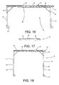
- the first covering structure 10 has, at the first open side 13, a roof 15 which can be at least partly lifted or opened to facilitate the passage of the platform 7 ( Figures 4, 19 - 22, 30 - 40).
- the roof 15 of the first covering structure 10 has a fixed part 16 and a mobile part 17 hinged to the fixed part 16 and which can be angled upwards relative to the fixed part 16.
- the mobile part 17 may also be angled downwards relative to the fixed part 16.
- the mobile part 17 of the roof 15 of the first covering structure 10 when in the angled position, can also be extended towards the outside of the first covering structure 10 ( Figures 4 and 22). In the embodiment illustrated this is achieved with a mobile part 17 configuration that is at least partly telescopic.
- the first covering structure 10 has a roof 15 which, at least at the first open side 13, can in turn be partly opened to facilitate the passage of the platform 7.
- the roof 15 of the first covering structure 10 has a fixed part 16 and a mobile part 17.
- the fixed part 16 advantageously (but not necessarily) has a C-shaped plan, whilst the mobile part 17 extends between the two arms of the C.
- the mobile part 17 is mobile between an active position in which it closes an opening 45 of the roof 15 (Figure 30) and a withdrawn position in which it leaves the opening 45 clear ( Figure 32) .
- the mobile part 17 advantageously consists of a roll-up device 46 (for example a sheet), designed to run, with its side edges, on the fixed part 16 ( Figure 33).
- a roll-up device 46 for example a sheet
- mobile supporting means 47 for the mobile part 17 which support the mobile part 17 in such a way that it projects outwards relative to the first covering structure 10.
- the mobile means 47 consist of two pull-out attachments 48 mounted on the fixed part 16.
- the mobile part 17 (the sheet) is motor-driven.
- control means for the mobile part, operatively connected both to the mobile part 17 motor (also not illustrated) and to special sensors (not illustrated) connected to the lift 5 and/or to the first covering structure 10.
- control means can be programmed to control the movement of the mobile part 17 according to the position of the platform 7, in such a way as to move the mobile part 17 to the withdrawn position when the platform 7 passes as it moves up or down.
- sensors in addition to sensors which detect the position of the platform 7, there may be safety sensors designed to check that the dimensions of the items loaded on the platform 7 do not exceed the dimensions of the part of the roof 15 which can be opened, to prevent accidental impact against the fixed part 16.
- the mobile part 17 comprises one or more covering panels 49, adjacent to one another and advantageously partly overlapping, to guarantee a seal against rain.
- each covering panel 49 is mounted on a bar 50 which is in turn hinged to a supporting beam 62 connected to the fixed part 16.
- each covering panel 49 is hinged relative to the fixed part 16 according to a horizontal axis of rotation, and is mobile between a central position in which it forms part of the roof 15 ( Figures 38 and 39 in which only the bars 50 are illustrated), and two limit positions rotated respectively upwards and downwards relative to the central position (not illustrated) in which they allow the platform 7 to pass.
- yielding supporting means 51 are attached to each covering panel 49 to hold it in the central position, in the absence of external stresses.
- these yielding supporting means 51 are in particular mounted between each bar 50 and the supporting beam 62, and comprise one or more spring-loaded hinges 52 which can rotate through approximately 90° about the central position of equilibrium.
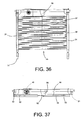
- each covering panel 49 (as well as the relative bar 50) can be divided into a plurality of pieces 53, starting from the supporting beam 62, each hinged to the previous one in the same way as the covering panel 49 as a whole is hinged relative to the fixed part 16. Therefore, as illustrated in Figure 40, there is a spring-loaded hinge 52 between each piece 53.
- the mobile supporting means 47 for the mobile part 17 which support the mobile part 17 in such a way that it projects outwards relative to the first covering structure 10.
- the mobile means 47 allow the supporting beam 62 to move along two side racks 54, parallel with the direction in which the bars 50 extend.
- the supporting beam 62 is mobile between a first limit position ( Figure 38) in which the covering panels 49 are partly inserted inside the fixed part 16, and a second limit position ( Figure 39) in which the covering panels 49 are completely outside the fixed part 16.
- the covering panels 49 (as well as the bars 50) must be divided into at least two pieces 53 so that, even when the supporting beam 62 is in the first position, at least one joint point is outside the fixed part, and therefore able to operate.
- the first covering structure 10 consists of a rigid frame 18 to which roll-up sheets 19 are attached which, once spread out cover its sides.
- Each sheet 19 is mobile between a rolled up condition in which it is rolled over itself, and a spread out condition in which it covers at least part of a side wall 20 of the first covering structure 10.
- the frame 18 has the shape of a parallelepiped and has at least two roll-up sheets 19, designed to cover at least two side walls 20.
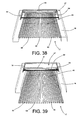
- the first covering structure 10 comprises a plurality of side protective panels 55.
- Each side protective panel 55 is mobile between a first position in which it forms a closed side surface of the first structure ( Figure 30), and a second position in which it allows passage through said side surface (relatively visible in Figure 37 where the structure is folded).
- the side protective panel 55 illustrated in Figures 35 and 36 consists of a framework 56 (Figure 35) covered by a sheet 57 ( Figure 36), in which holes (not illustrated) may be cut to prevent the side protective panel 55 from behaving like a sail in the wind.
- the two side protective panels 55 mounted on the short side of the first covering structure 10 may each be hinged to a leg (upright 21) of the first supporting structure 10, and to the side protective panel 55 mounted on the long side (case illustrated).
- the panels 55 may also be mounted in a removable fashion.
- the side protective panel 55 mounted on the long side may, for example, be mounted in a removable fashion, and be hinged to the roof 15 of the first covering structure 10 (case illustrated).
- the first covering structure 10 is also fitted with locking elements 58 designed to hold the side protective panels 55 in position.
- the side protective panels 55 consist of several parts connected in the appropriate way.
- the frame 18 of the first covering structure 10 has a plurality of vertical uprights 21 and horizontal crosspieces 22 connected to the vertical uprights 21, even using special locking pistons 23.
- at least the crosspiece 24 at the first open side 13 is partly removable to allow the passage of the platform 7 (Figure 23).
- Figures 16 and 18 are schematic side views of two alternative embodiments of the first covering structure 10.
- the uprights 21 have a fixed length
- the uprights are height-adjustable, since they have a telescopic structure with a plurality of predetermined levels 25 ( Figure 18).
- the height may be adjusted using any other method in addition to use of a telescopic structure.
- the uprights 21 can be fixed at different heights to angle the roof 15.
- the vehicle 2 also has at least a second compartment 26 in which the first covering structure 10 can be inserted when it is not used or when moving the apparatus 1.
- the first covering structure 10 may also be inserted directly in the first compartment 3, or may be transported using an auxiliary vehicle.
- the second compartment 26 extends in the upper part of the vehicle 2 above the first compartment 3 (as illustrated in the accompanying drawings), or at the side of the first compartment 3 (solution not illustrated), or below the floor of the first compartment 3 (this solution also not illustrated) .
- the first covering structure 10 can be moved between an open operating condition in which it can cover the platform 7 and a non-operating condition in which it is folded on itself (Figures 15 and 17). Folding of the first covering structure 10 involves folding the vertical uprights 21 which form the supporting legs under the crosspieces 22 which form the roof 15. Moreover, the frame 18 of the first covering structure 10 has at least one projecting upper portion 27 which can be inserted in the second compartment 26 when the first structure is in the operating condition.
- the latter has at least one insertion guide 28, whilst the first covering structure 10 has guide elements 29 (consisting of idle wheels) which can be coupled to the insertion guide 28.
- the side crosspieces 22 of the first supporting structure may also be fitted with a rack 30 designed to engage with a special motor-driven gear wheel (not illustrated) which allows the first covering structure 10 to be inserted in and removed from the second compartment 26 in an automated fashion.
- the frame 18 of the first covering structure 10 is rigid and can be directly drawn like a road trailer (by the vehicle 2 or by another vehicle).
- the first covering structure 10 is mounted on idle wheels 31 which allow it to be easily moved over the ground, but, to prevent accidental movements, it can also be made without wheels 31, or fitted with suitable supports (not illustrated) designed to lift the wheels 31 off the ground when the first covering structure 10 is assembled in the operating position.
- the apparatus 1 also comprises one or more stiffening elements 32 to lock the position of the covering structures relative to the vehicle 2 and/or to the lift 5 ( Figures 2 and 3).
- the second covering structure 11 in the preferred embodiment it has a bellows-style shape ( Figure 14), so that it can connect the vehicle 2 and the first covering structure 10, adjusting to their reciprocal position.
- the second covering structure 11 Since the second covering structure 11 is assembled between the vehicle 2 and the first covering structure 10, it can only be attached to them and be raised off the ground.
- the second covering structure 11 may have a rigid end 59 which can rest on the ground and be connected to the first covering structure 10 and a mobile end 60 which can be fixed to the vehicle 2 using belts 61.
- the vehicle 2 around the loading - unloading opening 4, the vehicle 2 has at least one seat 33 to which the second covering structure 11 is connected.
- the second covering structure 11 is mobile between an operating condition in which it is at least partly outside the seat 33 and can be connected to the first covering structure 10 using special hooks 34 ( Figure 14), and a travelling condition in which it is inserted in the seat 33 ( Figure 13).
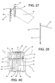
- the temporary protective means 12 comprise at least one roll-up sheet 35 attached to the platform 7 and mobile between a home condition in which it is rolled up over itself ( Figures 24 and 25) and a covering condition in which it covers the platform 7.
- the platform 7 is also fitted with couplings 36 ( Figure 26) to hold the sheet 35 in the covering condition.
- the platform 7 comprises a loading surface 37 and a plurality of tilting side boards 38.
- the roll-up sheet 35 can be attached both to below the loading surface 37 ( Figure 24) and to a side board 38 ( Figure 25).
- the removal apparatus 1 disclosed may be completed with further accessory parts.
- auxiliary structure 39 which can be attached to the storey of the building 6 to which the lift 5 is connected (at the balcony 40 as illustrated in Figures 2 to 5, or to the window 41 as illustrated in Figures 6 and 7), with at least one coupling element 42 designed to hold the roll-up sheet 35 of the temporary protective means 12 in a loading - unloading condition in which it covers and protects the platform 7 but at the same time allows platform access.
- the auxiliary structure 39 comprises two vertical columns 43 with a plurality of coupling elements 42 positioned at different heights.
- the auxiliary structure 39 can, therefore, be adapted to any operating situation.
- auxiliary structure 39 also comprises a canopy 44 mounted in such a way that it projects on the vertical columns 43.
- Assembly of the apparatus 1 disclosed involves initially assembly of the lift 5 using the known methods, then positioning the vehicle 2 near the lift 5.
- the first covering structure 10 is positioned (if necessary preceded by its assembly) at the base of the lift 5.
- the first covering structure 10 is removed from the second compartment 26, manually or automatically ( Figures 9 - 12).
- the vertical uprights 21 are lowered relative to the roof 15 and fixed to the crosspieces 22 using the locking pistons 23 ( Figures 10 - 11).
- the projecting portion of the frame 18 is also taken out of the second compartment 26.
- the first covering structure 10 is then positioned above the platform 7 when the platform is in the lower position, and the roof 15 is, if necessary, opened and extended (and the relative crosspiece 24 is removed).
- the opening 4 in the roof 15 is only necessary when the lift 5 is assembled with a gradient greater than a predetermined limit.
- the first covering structure 10 is locked to the vehicle 2 and/or the lift 5 by means of the stiffening elements.
- the second covering structure 11 is then removed from its seat 33 and fixed to the first covering structure 10.
- auxiliary structure 39 may also be assembled, which can be attached to the balcony 40, or, using special clamps not illustrated, to the window 41 jambs.
- the furniture loaded on the platform 7 is covered by the temporary protective means 12 which, when the platform 7 is in the upper position, can be connected to the auxiliary structure 39 as illustrated in Figures 3, 4 and 7, so that its protection from the weather is guaranteed during unloading.
- the furniture can be covered either with nylon and sheets, or with special parts fitted on either the vehicle 2 or the lift 5.
- the covering panels 49 can move from the central position to the limit positions by means of manual or motor-driven mechanical operation, or, preferably, by impact of the platform 7 or the furniture loaded on them.
- the present invention brings important advantages.
- the apparatus disclosed guarantees protection against the weather both for the items to be moved and the removal men/women, along the entire path from the vehicle to the apartment.
- the apparatus can also be used to provide shade from the sun, for both the furniture or other delicate and valuable items, and for the removal workers, allowing them to operate in a more agreeable environment.
- the apparatus disclosed may be assembled even where space is limited and the vehicle cannot be positioned directly alongside the lift.
- the roll-up device 46 configuration of the temporary protective means in no way hinders access to the loading platform and allows them to be adjusted to any item transported, irrespective of its dimensions.
- the first covering structure guarantees shelter from the weather at the platform loading zone, that is to say, where, due to the need to correctly position the furniture, it is not possible to keep it covered even with nylon or sheets.
Landscapes
- Engineering & Computer Science (AREA)
- Structural Engineering (AREA)
- Transportation (AREA)
- Civil Engineering (AREA)
- Automation & Control Theory (AREA)
- Mechanical Engineering (AREA)
- Tents Or Canopies (AREA)
- Mechanical Treatment Of Semiconductor (AREA)
- Weting (AREA)
- Vehicle Cleaning, Maintenance, Repair, Refitting, And Outriggers (AREA)
- Electrical Discharge Machining, Electrochemical Machining, And Combined Machining (AREA)
Claims (36)
- Un système de déménagement comprenant un véhicule (2) avec au moins un premier compartiment (3) pour transporter des objets à déménager, et accessible de l'extérieur par au moins une ouverture de chargement - déchargement (4), des moyens de couverture (9), comprenant au moins une deuxième structure de couverture associée à l'ouverture de chargement - déchargement (4) du véhicule (2), ledit système de déménagement étant caractérisé en ce qu'il comprend également un élévateur transportable (5), pouvant être assemblé près d'un bâtiment (6), et équipé d'une plate-forme de transport (7) mobile entre une position inférieure proche du sol et une position supérieure au niveau d'un étage prédéterminé du bâtiment (6), et en ce qu'il présente un passage pour le transfert des objets à déménager entre le véhicule (2) et la position supérieure de la plate-forme (7), lesdits moyens de couverture (9) pouvant être placés de façon à couvrir l'intégralité du passage et protéger ainsi des intempéries les objets à déménager, lesdits moyens de couverture (9) comprenant en outre :- au moins une première structure de couverture (10) pouvant être assemblée dans la position inférieure de la plate-forme (7) pour protéger la plate-forme (7) des intempéries quand elle est dans la position inférieure ; et- des moyens de protection temporaires (12), qui peuvent être fixés à la plate-forme (7) pour la couvrir pendant les mouvements entre la position inférieure et la position supérieure ;la deuxième structure de couverture (11) pouvant être assemblée entre la première structure de couverture (10) et l'ouverture de chargement - déchargement (4) du véhicule (2) pour créer un passage couvert entre le véhicule (2) et la plate-forme (7) dans sa position inférieure, et la première structure de couverture (10) ayant un toit (15) qui peut être soulevé ou ouvert au moins partiellement pour faciliter le passage de la plate-forme (7).
- Le système de déménagement selon la revendication 1, caractérisé en ce que la première structure de couverture (10) a au moins un premier côté ouvert (13) pour permettre le passage de la plate-forme (7), et au moins un deuxième côté ouvert (14) communiquant avec la deuxième structure de couverture (11).
- Le système de déménagement selon la revendication 2, caractérisé en ce que le toit (15) peut être au moins partiellement soulevé pour faciliter le passage de la plate-forme (7) au premier côté ouvert (13).
- Le système de déménagement selon la revendication 3, caractérisé en ce que le toit (15) de la première structure de couverture (10) a une partie fixe (16) et une partie mobile (17) articulée sur la partie fixe (16) et pouvant être orientée vers le bas et/ou vers le haut par rapport à la partie fixe (16).
- Le système de déménagement selon la revendication 4, caractérisé en ce que la partie mobile (17) est également extensible lorsqu'elle est orientée vers le haut.
- Le système de déménagement selon la revendication 5, caractérisé en ce que la partie mobile (17) a une structure télescopique.
- Le système de déménagement selon la revendication 1, caractérisé en ce que le toit (15) de la première structure de couverture (10) a une partie fixe (16) et une partie mobile (17).
- Le système de déménagement selon la revendication 7, caractérisé en ce que la partie mobile (17) se déplace entre une position active où elle ferme une ouverture (45) du toit (15) et une position rentrée où elle laisse l'ouverture (45) libre.
- Le système de déménagement selon l'une quelconque des revendications 7 ou 8, caractérisé en ce que la partie mobile (17) consiste en un dispositif à enroulement (46).
- Le système de déménagement selon l'une quelconque des revendications de 7 à 9, caractérisé en ce que la partie mobile (17) reçoit le mouvement d'un moteur.
- Le système de déménagement selon la revendication 10, caractérisé en ce que le mouvement de la partie mobile (17) est commandé en fonction de la position de la plate-forme (7), de façon à déplacer la partie mobile dans la position rentrée au passage de la plate-forme (7).
- Système de déménagement selon la revendication 7, caractérisé en ce que la partie mobile (17) comprend un ou plusieurs panneaux de couverture adjacents (49), chacun étant articulé à la partie fixe (16) selon un axe de rotation horizontal, et se déplace entre une position centrale où elle fait partie du toit (15) et deux positions limites orientées respectivement vers le haut et vers le bas par rapport à la position centrale, dans laquelle elle permet le passage de la plate-forme (7).
- Le système de déménagement selon la revendication 12, caractérisé en ce que la partie mobile comprend aussi des moyens de support élastiques (51) fixés à chacun des panneaux de couverture (49) pour les tenir dans la position centrale en l'absence de forces externes.
- Le système de déménagement selon la revendication 13, caractérisé en ce que les moyens de support élastiques (51) comprennent au moins une charnière à ressort (52).
- Le système de déménagement selon la revendication 12, 13 ou 14, caractérisé en ce que chaque panneau de couverture (49) est subdivisé en une pluralité de pièces (53), chacune étant articulée à la précédente de la même façon que le panneau de couverture (49) entier est articulé par rapport à la partie fixe.
- Le système de déménagement selon l'une quelconque des revendications de 7 à 15, caractérisé en ce qu'il comprend des moyens de support mobiles (47) qui soutiennent la partie mobile (17) de manière à ce qu'elle soit en saillie à l'extérieur par rapport à la première structure de couverture (10).
- Le système de déménagement selon l'une quelconque des revendications de 2 à 16, caractérisé en ce que la première structure de couverture (10) présente une pluralité de montants verticaux (21) et de traverses horizontales (22) connectées aux montants verticaux (21), avec au moins l'une des traverses (22), (24), positionnée du premier côté ouvert (13),au moins partiellement amovible pour faciliter le passage de la plate-forme (7).
- Le système de déménagement selon l'une quelconque des revendications précédentes, caractérisé en ce que la première structure de couverture (10) comprend aussi une pluralité de feuilles à enroulement (19) pour couvrir ses côtés.
- Le système de déménagement selon la revendication 18, caractérisé en ce que chacune des feuilles (19) est mobile entre une position enroulée où elle est enroulée sur elle-même et une position déroulée où elle forme une surface latérale fermée de la première structure de couverture (10).
- Le système de déménagement selon l'une quelconque des revendications de 1 à 17, caractérisé en ce que la première structure de couverture (10) comprend aussi une pluralité de panneaux latéraux de protection (55).
- Le système de déménagement selon la revendication 20, caractérisé en ce que chacune des panneaux latéraux de protection (55) est mobile entre une première position où il forme une surface latérale fermée de la première structure (10) et une deuxième position où il permet le passage à travers la surface latérale.
- Le système de déménagement selon l'une quelconque des revendications précédentes, caractérisé en ce que le véhicule (2) est également doté d'un deuxième compartiment (26) et en ce que la première structure de couverture (10) peut être insérée dans le deuxième compartiment (26).
- Le système de déménagement selon la revendication 22, caractérisé en ce que la première structure de couverture (10) peut être déplacée entre une position opérationnelle où elle peut couvrir la plate-forme (7) et une position non opérationnelle où elle est repliée sur elle-même et peut être insérée dans le deuxième compartiment (26).
- Le système de déménagement selon la revendication 22 ou 23, caractérisé en ce que le deuxième compartiment (26) s'étend dans la partie supérieure du véhicule (2), dans une partie latérale du véhicule (2) ou dans une partie inférieure du véhicule (2).
- Le système de déménagement selon la revendication 24, caractérisé en ce que la première structure de couverture (10) présente au moins une portion supérieure saillante (27) qui peut être insérée dans le deuxième compartiment (26) lorsqu'elle est en position opérationnelle, ladite structure pouvant ensuite être ramenée en position non opérationnelle.
- Le système de déménagement selon la revendication 24 ou 25, caractérisé en ce que le deuxième compartiment (26) a au moins un guide d'insertion (28) pour guider l'introduction et le retrait de la première structure de couverture (10), et en ce que la première structure de couverture (10) a des éléments de guidage (29) qui peuvent être couplés au guide d'insertion (28).
- Le système de déménagement selon l'une quelconque des revendications précédentes, caractérisé en ce que la première structure de couverture (10) a une pluralité de pieds de support verticaux réglables en hauteur.
- Le système de déménagement selon l'une quelconque des revendications précédentes, caractérisé en ce que la première structure de couverture (10) est montée sur des roues libres (31).
- Le système de déménagement selon l'une quelconque des revendications précédentes, caractérisé en ce qu'il comprend aussi un ou plusieurs éléments de renforcement (32) pour bloquer la position des structures de couverture par rapport au véhicule (2) et/ou à l'élévateur (5).
- Le système de déménagement selon l'une quelconque des revendications précédentes, caractérisé en ce que la deuxième structure de couverture (11) est en forme de soufflet.
- Le système de déménagement selon l'une quelconque des revendications 1 à 29, caractérisé en ce que la deuxième structure de couverture (11) a une extrémité rigide (59) qui peut être connectée à la première structure de couverture (10), et une extrémité mobile (60) qui peut être fixée au véhicule (2).
- Le système de déménagement selon l'une quelconque des revendications précédentes, caractérisé en ce que le véhicule (2) a au moins un logement (33) autour de l'ouverture de chargement - déchargement (4), la deuxième structure de couverture (11) étant connectée au logement (33) et étant mobile entre une position opérationnelle où elle est au moins partiellement hors du logement (33) et peut être connectée à la première structure de couverture (10) et une position de voyage où elle est insérée dans le logement (33).
- Le système de déménagement selon l'une quelconque des revendications précédentes, caractérisé en ce que les protections temporaires (12) comprennent au moins une feuille à enroulement (35) pouvant être fixée à la plate-forme (7) et être déplacée entre une position de repos où elle est enroulée sur elle-même et une position de couverture où elle couvre la plate-forme (7), la plate-forme (7) étant aussi dotée d'éléments de retenue (36) pour maintenir la feuille (35) dans la position de couverture.
- Le système de déménagement selon l'une quelconque des revendications précédentes, caractérisé en ce qu'il comprend aussi une structure auxiliaire (39), qui peut être fixée à l'étage du bâtiment (6) auquel l'élévateur (5) est relié quand il est utilisé, la structure auxiliaire (39) comprenant au moins un élément de retenue (42) pour maintenir les protections temporaires (12) dans une condition de chargement - déchargement, dans laquelle elles couvrent la plate-forme (7) tout en permettant l'accès à cette dernière.
- Le système de déménagement selon la revendication 34, caractérisé en ce que la structure auxiliaire (39) comprend aussi un auvent (44) pour protéger davantage la plate-forme (7).
- Une première structure de couverture (10) pour un système de déménagement à assembler à la position inférieure de la plate-forme (7) d'un élévateur (5) du système de déménagement pour protéger ladite plate-forme (7) des intempéries quand elle est dans la position inférieure, caractérisée en ce que la première structure de couverture (10) est faite selon l'une quelconque des revendications précédentes.
Applications Claiming Priority (2)
| Application Number | Priority Date | Filing Date | Title |
|---|---|---|---|
| ITVR20030118 | 2003-10-15 | ||
| IT000118A ITVR20030118A1 (it) | 2003-10-15 | 2003-10-15 | Attrezzatura per traslochi. |
Publications (2)
| Publication Number | Publication Date |
|---|---|
| EP1548211A1 EP1548211A1 (fr) | 2005-06-29 |
| EP1548211B1 true EP1548211B1 (fr) | 2006-08-02 |
Family
ID=34531959
Family Applications (1)
| Application Number | Title | Priority Date | Filing Date |
|---|---|---|---|
| EP04023299A Expired - Lifetime EP1548211B1 (fr) | 2003-10-15 | 2004-09-30 | Système de déménagement |
Country Status (4)
| Country | Link |
|---|---|
| EP (1) | EP1548211B1 (fr) |
| AT (1) | ATE335111T1 (fr) |
| DE (1) | DE602004001749T2 (fr) |
| IT (1) | ITVR20030118A1 (fr) |
Family Cites Families (4)
| Publication number | Priority date | Publication date | Assignee | Title |
|---|---|---|---|---|
| GB2140479A (en) * | 1983-05-10 | 1984-11-28 | Guerrero Jesus Villa | Folding shelters |
| DE3633505A1 (de) * | 1985-10-10 | 1987-04-16 | Boecker Albert Gmbh & Co Kg | Lastenpritsche fuer schraegaufzuege |
| JPH11342785A (ja) * | 1998-06-02 | 1999-12-14 | Kanto Giken:Kk | 引越用貨物自動車 |
| DE20213307U1 (de) * | 2002-08-29 | 2002-10-24 | hymer idc GmbH & Co.KG, 88339 Bad Waldsee | Umbausatz für ein Kraftfahrzeug und Kraftfahrzeug |
-
2003
- 2003-10-15 IT IT000118A patent/ITVR20030118A1/it unknown
-
2004
- 2004-09-30 AT AT04023299T patent/ATE335111T1/de not_active IP Right Cessation
- 2004-09-30 EP EP04023299A patent/EP1548211B1/fr not_active Expired - Lifetime
- 2004-09-30 DE DE602004001749T patent/DE602004001749T2/de not_active Expired - Fee Related
Also Published As
| Publication number | Publication date |
|---|---|
| ITVR20030118A1 (it) | 2005-04-16 |
| DE602004001749T2 (de) | 2007-10-04 |
| EP1548211A1 (fr) | 2005-06-29 |
| DE602004001749D1 (de) | 2006-09-14 |
| ATE335111T1 (de) | 2006-08-15 |
Similar Documents
| Publication | Publication Date | Title |
|---|---|---|
| US4635412A (en) | Folding house transportable in the form of a stackable container | |
| CA1325032C (fr) | Annexe | |
| US5862827A (en) | Mobile and adjustable elevated platform | |
| US5237784A (en) | Shelter container fit for habitation with extendible inner volume | |
| US3737190A (en) | Camper unit | |
| US12296662B2 (en) | Automotive cargo/tray cover assembly | |
| IE60765B1 (en) | Transportable construction element in the form of a container | |
| US20160096465A1 (en) | Railing system, particularly for travel trailers | |
| GB1572352A (en) | Vehicle body | |
| US20220097593A1 (en) | Vehicle Mounted Enclosure | |
| WO2017042575A1 (fr) | Toits relevable pour véhicules | |
| EP1363804B1 (fr) | V hicule ravitailleur d'a ronef couvert | |
| US6220657B1 (en) | Cover system for a golf cart | |
| US3254657A (en) | Camping device and method | |
| KR102403573B1 (ko) | 자동 루프탑 텐트가 구비된 차량 | |
| EP1548211B1 (fr) | Système de déménagement | |
| US3259422A (en) | Sleeper unit for station wagons and the like | |
| US2806478A (en) | Collapsible shelter device for motor vehicles | |
| US3078117A (en) | Camping and touring trailer | |
| AU2021254582B2 (en) | Stowable Veranda for Recreational Vehicle | |
| KR101836105B1 (ko) | 화물트럭의 덮개 장치 | |
| CN109383360A (zh) | 一种车顶具有可扩充空间的房车 | |
| US20210371016A1 (en) | Rack System for Pickup Trucks | |
| RU223175U1 (ru) | Кузов транспортного средства, трансформируемый в сцену | |
| CN107650771B (zh) | 一种自主升降系统及其使用方法 |
Legal Events
| Date | Code | Title | Description |
|---|---|---|---|
| PUAI | Public reference made under article 153(3) epc to a published international application that has entered the european phase |
Free format text: ORIGINAL CODE: 0009012 |
|
| AK | Designated contracting states |
Kind code of ref document: A1 Designated state(s): AT BE BG CH CY CZ DE DK EE ES FI FR GB GR HU IE IT LI LU MC NL PL PT RO SE SI SK TR |
|
| AX | Request for extension of the european patent |
Extension state: AL HR LT LV MK |
|
| 17P | Request for examination filed |
Effective date: 20050511 |
|
| GRAP | Despatch of communication of intention to grant a patent |
Free format text: ORIGINAL CODE: EPIDOSNIGR1 |
|
| AKX | Designation fees paid |
Designated state(s): AT BE BG CH CY CZ DE DK EE ES FI FR GB GR HU IE IT LI LU MC NL PL PT RO SE SI SK TR |
|
| RIC1 | Information provided on ipc code assigned before grant |
Ipc: E04H 15/00 20060101AFI20060221BHEP Ipc: B60P 1/00 20060101ALI20060221BHEP |
|
| GRAS | Grant fee paid |
Free format text: ORIGINAL CODE: EPIDOSNIGR3 |
|
| GRAA | (expected) grant |
Free format text: ORIGINAL CODE: 0009210 |
|
| AK | Designated contracting states |
Kind code of ref document: B1 Designated state(s): AT BE BG CH CY CZ DE DK EE ES FI FR GB GR HU IE IT LI LU MC NL PL PT RO SE SI SK TR |
|
| PG25 | Lapsed in a contracting state [announced via postgrant information from national office to epo] |
Ref country code: RO Free format text: LAPSE BECAUSE OF FAILURE TO SUBMIT A TRANSLATION OF THE DESCRIPTION OR TO PAY THE FEE WITHIN THE PRESCRIBED TIME-LIMIT Effective date: 20060802 Ref country code: PL Free format text: LAPSE BECAUSE OF FAILURE TO SUBMIT A TRANSLATION OF THE DESCRIPTION OR TO PAY THE FEE WITHIN THE PRESCRIBED TIME-LIMIT Effective date: 20060802 Ref country code: NL Free format text: LAPSE BECAUSE OF FAILURE TO SUBMIT A TRANSLATION OF THE DESCRIPTION OR TO PAY THE FEE WITHIN THE PRESCRIBED TIME-LIMIT Effective date: 20060802 Ref country code: SK Free format text: LAPSE BECAUSE OF FAILURE TO SUBMIT A TRANSLATION OF THE DESCRIPTION OR TO PAY THE FEE WITHIN THE PRESCRIBED TIME-LIMIT Effective date: 20060802 Ref country code: SI Free format text: LAPSE BECAUSE OF FAILURE TO SUBMIT A TRANSLATION OF THE DESCRIPTION OR TO PAY THE FEE WITHIN THE PRESCRIBED TIME-LIMIT Effective date: 20060802 Ref country code: BE Free format text: LAPSE BECAUSE OF FAILURE TO SUBMIT A TRANSLATION OF THE DESCRIPTION OR TO PAY THE FEE WITHIN THE PRESCRIBED TIME-LIMIT Effective date: 20060802 Ref country code: AT Free format text: LAPSE BECAUSE OF FAILURE TO SUBMIT A TRANSLATION OF THE DESCRIPTION OR TO PAY THE FEE WITHIN THE PRESCRIBED TIME-LIMIT Effective date: 20060802 Ref country code: CZ Free format text: LAPSE BECAUSE OF FAILURE TO SUBMIT A TRANSLATION OF THE DESCRIPTION OR TO PAY THE FEE WITHIN THE PRESCRIBED TIME-LIMIT Effective date: 20060802 Ref country code: LI Free format text: LAPSE BECAUSE OF FAILURE TO SUBMIT A TRANSLATION OF THE DESCRIPTION OR TO PAY THE FEE WITHIN THE PRESCRIBED TIME-LIMIT Effective date: 20060802 Ref country code: CH Free format text: LAPSE BECAUSE OF FAILURE TO SUBMIT A TRANSLATION OF THE DESCRIPTION OR TO PAY THE FEE WITHIN THE PRESCRIBED TIME-LIMIT Effective date: 20060802 Ref country code: FI Free format text: LAPSE BECAUSE OF FAILURE TO SUBMIT A TRANSLATION OF THE DESCRIPTION OR TO PAY THE FEE WITHIN THE PRESCRIBED TIME-LIMIT Effective date: 20060802 |
|
| REG | Reference to a national code |
Ref country code: GB Ref legal event code: FG4D |
|
| REG | Reference to a national code |
Ref country code: CH Ref legal event code: EP |
|
| REG | Reference to a national code |
Ref country code: IE Ref legal event code: FG4D |
|
| REF | Corresponds to: |
Ref document number: 602004001749 Country of ref document: DE Date of ref document: 20060914 Kind code of ref document: P |
|
| PG25 | Lapsed in a contracting state [announced via postgrant information from national office to epo] |
Ref country code: MC Free format text: LAPSE BECAUSE OF NON-PAYMENT OF DUE FEES Effective date: 20060930 |
|
| PG25 | Lapsed in a contracting state [announced via postgrant information from national office to epo] |
Ref country code: SE Free format text: LAPSE BECAUSE OF FAILURE TO SUBMIT A TRANSLATION OF THE DESCRIPTION OR TO PAY THE FEE WITHIN THE PRESCRIBED TIME-LIMIT Effective date: 20061102 Ref country code: DK Free format text: LAPSE BECAUSE OF FAILURE TO SUBMIT A TRANSLATION OF THE DESCRIPTION OR TO PAY THE FEE WITHIN THE PRESCRIBED TIME-LIMIT Effective date: 20061102 Ref country code: BG Free format text: LAPSE BECAUSE OF FAILURE TO SUBMIT A TRANSLATION OF THE DESCRIPTION OR TO PAY THE FEE WITHIN THE PRESCRIBED TIME-LIMIT Effective date: 20061102 |
|
| PG25 | Lapsed in a contracting state [announced via postgrant information from national office to epo] |
Ref country code: ES Free format text: LAPSE BECAUSE OF FAILURE TO SUBMIT A TRANSLATION OF THE DESCRIPTION OR TO PAY THE FEE WITHIN THE PRESCRIBED TIME-LIMIT Effective date: 20061113 |
|
| NLV1 | Nl: lapsed or annulled due to failure to fulfill the requirements of art. 29p and 29m of the patents act | ||
| PG25 | Lapsed in a contracting state [announced via postgrant information from national office to epo] |
Ref country code: PT Free format text: LAPSE BECAUSE OF FAILURE TO SUBMIT A TRANSLATION OF THE DESCRIPTION OR TO PAY THE FEE WITHIN THE PRESCRIBED TIME-LIMIT Effective date: 20070102 |
|
| REG | Reference to a national code |
Ref country code: CH Ref legal event code: PL |
|
| ET | Fr: translation filed | ||
| PLBE | No opposition filed within time limit |
Free format text: ORIGINAL CODE: 0009261 |
|
| STAA | Information on the status of an ep patent application or granted ep patent |
Free format text: STATUS: NO OPPOSITION FILED WITHIN TIME LIMIT |
|
| 26N | No opposition filed |
Effective date: 20070503 |
|
| PGFP | Annual fee paid to national office [announced via postgrant information from national office to epo] |
Ref country code: DE Payment date: 20071004 Year of fee payment: 4 |
|
| PG25 | Lapsed in a contracting state [announced via postgrant information from national office to epo] |
Ref country code: GR Free format text: LAPSE BECAUSE OF FAILURE TO SUBMIT A TRANSLATION OF THE DESCRIPTION OR TO PAY THE FEE WITHIN THE PRESCRIBED TIME-LIMIT Effective date: 20061103 |
|
| PGFP | Annual fee paid to national office [announced via postgrant information from national office to epo] |
Ref country code: FR Payment date: 20070928 Year of fee payment: 4 |
|
| PG25 | Lapsed in a contracting state [announced via postgrant information from national office to epo] |
Ref country code: EE Free format text: LAPSE BECAUSE OF FAILURE TO SUBMIT A TRANSLATION OF THE DESCRIPTION OR TO PAY THE FEE WITHIN THE PRESCRIBED TIME-LIMIT Effective date: 20060802 |
|
| PG25 | Lapsed in a contracting state [announced via postgrant information from national office to epo] |
Ref country code: HU Free format text: LAPSE BECAUSE OF FAILURE TO SUBMIT A TRANSLATION OF THE DESCRIPTION OR TO PAY THE FEE WITHIN THE PRESCRIBED TIME-LIMIT Effective date: 20070203 Ref country code: TR Free format text: LAPSE BECAUSE OF FAILURE TO SUBMIT A TRANSLATION OF THE DESCRIPTION OR TO PAY THE FEE WITHIN THE PRESCRIBED TIME-LIMIT Effective date: 20060802 Ref country code: LU Free format text: LAPSE BECAUSE OF NON-PAYMENT OF DUE FEES Effective date: 20060930 |
|
| PG25 | Lapsed in a contracting state [announced via postgrant information from national office to epo] |
Ref country code: CY Free format text: LAPSE BECAUSE OF FAILURE TO SUBMIT A TRANSLATION OF THE DESCRIPTION OR TO PAY THE FEE WITHIN THE PRESCRIBED TIME-LIMIT Effective date: 20060802 |
|
| GBPC | Gb: european patent ceased through non-payment of renewal fee |
Effective date: 20080930 |
|
| REG | Reference to a national code |
Ref country code: FR Ref legal event code: ST Effective date: 20090529 |
|
| PG25 | Lapsed in a contracting state [announced via postgrant information from national office to epo] |
Ref country code: IE Free format text: LAPSE BECAUSE OF NON-PAYMENT OF DUE FEES Effective date: 20080930 |
|
| PG25 | Lapsed in a contracting state [announced via postgrant information from national office to epo] |
Ref country code: DE Free format text: LAPSE BECAUSE OF NON-PAYMENT OF DUE FEES Effective date: 20090401 Ref country code: IT Free format text: LAPSE BECAUSE OF NON-PAYMENT OF DUE FEES Effective date: 20080930 |
|
| PGFP | Annual fee paid to national office [announced via postgrant information from national office to epo] |
Ref country code: IE Payment date: 20071011 Year of fee payment: 4 |
|
| PG25 | Lapsed in a contracting state [announced via postgrant information from national office to epo] |
Ref country code: FR Free format text: LAPSE BECAUSE OF NON-PAYMENT OF DUE FEES Effective date: 20080930 |
|
| PGFP | Annual fee paid to national office [announced via postgrant information from national office to epo] |
Ref country code: IT Payment date: 20070930 Year of fee payment: 4 |
|
| PG25 | Lapsed in a contracting state [announced via postgrant information from national office to epo] |
Ref country code: GB Free format text: LAPSE BECAUSE OF NON-PAYMENT OF DUE FEES Effective date: 20080930 |