EP1548211B1 - A removal apparatus - Google Patents
A removal apparatus Download PDFInfo
- Publication number
- EP1548211B1 EP1548211B1 EP04023299A EP04023299A EP1548211B1 EP 1548211 B1 EP1548211 B1 EP 1548211B1 EP 04023299 A EP04023299 A EP 04023299A EP 04023299 A EP04023299 A EP 04023299A EP 1548211 B1 EP1548211 B1 EP 1548211B1
- Authority
- EP
- European Patent Office
- Prior art keywords
- removal apparatus
- platform
- covering
- covering structure
- mobile
- Prior art date
- Legal status (The legal status is an assumption and is not a legal conclusion. Google has not performed a legal analysis and makes no representation as to the accuracy of the status listed.)
- Not-in-force
Links
Images


Classifications
-
- B—PERFORMING OPERATIONS; TRANSPORTING
- B66—HOISTING; LIFTING; HAULING
- B66B—ELEVATORS; ESCALATORS OR MOVING WALKWAYS
- B66B9/00—Kinds or types of lifts in, or associated with, buildings or other structures
- B66B9/16—Mobile or transportable lifts specially adapted to be shifted from one part of a building or other structure to another part or to another building or structure
- B66B9/193—Mobile or transportable lifts specially adapted to be shifted from one part of a building or other structure to another part or to another building or structure with inclined liftways
-
- B—PERFORMING OPERATIONS; TRANSPORTING
- B60—VEHICLES IN GENERAL
- B60P—VEHICLES ADAPTED FOR LOAD TRANSPORTATION OR TO TRANSPORT, TO CARRY, OR TO COMPRISE SPECIAL LOADS OR OBJECTS
- B60P1/00—Vehicles predominantly for transporting loads and modified to facilitate loading, consolidating the load, or unloading
Definitions
- the present invention relates to a removal apparatus of the type described in the preamble of claim 1.
- An apparatus of this kind is disclosed in JP 11342785.
- the removal apparatuses used today consists of a transport vehicle inside which furniture and other items to be moved are transported, and a lift with a mobile platform that allows the furniture and other items to be transferred directly from the road, where the vehicle is parked, to the balcony or window of the apartment involved in the move, and vice versa.
- patent JP 11342785 describes a removal vehicle with canopies which can be pulled out of the side to cover the area next to the vehicle loading - unloading opening.
- the technical need which forms the basis of the present invention is to provide a removal apparatus which is easy to use even in the event of precipitation, and which guarantees protection from the weather both for the items moved, irrespective of their size, and the removal operators.
- the technical need of the present invention is also to provide a removal apparatus which guarantees this result especially at the lift platform loading/unloading area.
- the technical need of the present invention is to provide a removal apparatus which guarantees this result substantially irrespective of the reciprocal position of the vehicle and the lift.
- the numeral 1 denotes as a whole a removal apparatus made according to the present invention.
- the apparatus 1 comprises a first covering structure 10 which can be fitted at a lower position of a platform 7 of a lift 5 to protect the platform 7 from the weather when it is in the lower position.
- This first covering structure 10 is therefore designed to protect both items and people during platform 7 loading and unloading at ground level.
- composition of the first covering structure 10 are provided below, relative to the most complete embodiment of the present invention.
- the apparatus 1 comprises firstly a vehicle 2, with at least a first compartment 3 for transporting the items to be moved.
- This first compartment 3 can be accessed from the outside through at least one loading - unloading opening 4, and a transportable lift 5, which can be assembled close to a building 6 and is equipped with a transport platform 7 mobile between a lower position in which it is close to the ground and an upper position in which it is at a predetermined storey of the building 6 (in Figure 3 the platform 7 is represented simultaneously in both positions).
- the accompanying drawings illustrate a lift 5 mounted on a driving carriage 8, of the conventional type.
- the path along which the items to be moved are transferred is fitted with special covering means 9 arranged in such a way as to cover the items to be moved along the entire path, protecting them from the weather.
- these covering means 9 comprise at least a first and a second covering structure 10, 11, and temporary protective means 12 which can be attached to the platform 7.
- the first covering structure 10 can be assembled at the base of the lift 5 so that it is over the platform 7 when the platform is in the lower position, protecting it from the weather during loading - unloading operations.
- the second covering structure 11 can be assembled between the first covering structure 10 and the vehicle 2 loading - unloading opening 4, to create a covered path between the vehicle 2 and the platform 7 when the platform is in the lower position.
- the temporary protective means 12 are attached to the platform 7 and are designed to cover it during movements between the lower position and the upper position.
- the first covering structure 10 has at least a first side 13 which is open to allow the passage of the platform 7, and at least a second side 14 which is open (or can be opened) communicating with the second covering structure 11, which allows the transfer of the items to be moved between the vehicle 2 and the platform 7 in the lower position and vice versa.
- the first covering structure 10 has, at the first open side 13, a roof 15 which can be at least partly lifted or opened to facilitate the passage of the platform 7 ( Figures 4, 19 - 22, 30 - 40).
- the roof 15 of the first covering structure 10 has a fixed part 16 and a mobile part 17 hinged to the fixed part 16 and which can be angled upwards relative to the fixed part 16.
- the mobile part 17 may also be angled downwards relative to the fixed part 16.
- the mobile part 17 of the roof 15 of the first covering structure 10 when in the angled position, can also be extended towards the outside of the first covering structure 10 ( Figures 4 and 22). In the embodiment illustrated this is achieved with a mobile part 17 configuration that is at least partly telescopic.
- the first covering structure 10 has a roof 15 which, at least at the first open side 13, can in turn be partly opened to facilitate the passage of the platform 7.
- the roof 15 of the first covering structure 10 has a fixed part 16 and a mobile part 17.
- the fixed part 16 advantageously (but not necessarily) has a C-shaped plan, whilst the mobile part 17 extends between the two arms of the C.
- the mobile part 17 is mobile between an active position in which it closes an opening 45 of the roof 15 (Figure 30) and a withdrawn position in which it leaves the opening 45 clear ( Figure 32) .
- the mobile part 17 advantageously consists of a roll-up device 46 (for example a sheet), designed to run, with its side edges, on the fixed part 16 ( Figure 33).
- a roll-up device 46 for example a sheet
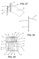
- mobile supporting means 47 for the mobile part 17 which support the mobile part 17 in such a way that it projects outwards relative to the first covering structure 10.
- the mobile means 47 consist of two pull-out attachments 48 mounted on the fixed part 16.
- the mobile part 17 (the sheet) is motor-driven.
- control means for the mobile part, operatively connected both to the mobile part 17 motor (also not illustrated) and to special sensors (not illustrated) connected to the lift 5 and/or to the first covering structure 10.
- control means can be programmed to control the movement of the mobile part 17 according to the position of the platform 7, in such a way as to move the mobile part 17 to the withdrawn position when the platform 7 passes as it moves up or down.
- sensors in addition to sensors which detect the position of the platform 7, there may be safety sensors designed to check that the dimensions of the items loaded on the platform 7 do not exceed the dimensions of the part of the roof 15 which can be opened, to prevent accidental impact against the fixed part 16.
- the mobile part 17 comprises one or more covering panels 49, adjacent to one another and advantageously partly overlapping, to guarantee a seal against rain.
- each covering panel 49 is mounted on a bar 50 which is in turn hinged to a supporting beam 62 connected to the fixed part 16.
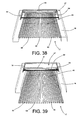
- each covering panel 49 is hinged relative to the fixed part 16 according to a horizontal axis of rotation, and is mobile between a central position in which it forms part of the roof 15 ( Figures 38 and 39 in which only the bars 50 are illustrated), and two limit positions rotated respectively upwards and downwards relative to the central position (not illustrated) in which they allow the platform 7 to pass.
- yielding supporting means 51 are attached to each covering panel 49 to hold it in the central position, in the absence of external stresses.
- these yielding supporting means 51 are in particular mounted between each bar 50 and the supporting beam 62, and comprise one or more spring-loaded hinges 52 which can rotate through approximately 90° about the central position of equilibrium.
- each covering panel 49 (as well as the relative bar 50) can be divided into a plurality of pieces 53, starting from the supporting beam 62, each hinged to the previous one in the same way as the covering panel 49 as a whole is hinged relative to the fixed part 16. Therefore, as illustrated in Figure 40, there is a spring-loaded hinge 52 between each piece 53.
- the mobile supporting means 47 for the mobile part 17 which support the mobile part 17 in such a way that it projects outwards relative to the first covering structure 10.
- the mobile means 47 allow the supporting beam 62 to move along two side racks 54, parallel with the direction in which the bars 50 extend.
- the supporting beam 62 is mobile between a first limit position ( Figure 38) in which the covering panels 49 are partly inserted inside the fixed part 16, and a second limit position ( Figure 39) in which the covering panels 49 are completely outside the fixed part 16.
- the covering panels 49 (as well as the bars 50) must be divided into at least two pieces 53 so that, even when the supporting beam 62 is in the first position, at least one joint point is outside the fixed part, and therefore able to operate.
- the first covering structure 10 consists of a rigid frame 18 to which roll-up sheets 19 are attached which, once spread out cover its sides.
- Each sheet 19 is mobile between a rolled up condition in which it is rolled over itself, and a spread out condition in which it covers at least part of a side wall 20 of the first covering structure 10.
- the frame 18 has the shape of a parallelepiped and has at least two roll-up sheets 19, designed to cover at least two side walls 20.
- the first covering structure 10 comprises a plurality of side protective panels 55.
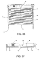
- Each side protective panel 55 is mobile between a first position in which it forms a closed side surface of the first structure ( Figure 30), and a second position in which it allows passage through said side surface (relatively visible in Figure 37 where the structure is folded).
- the side protective panel 55 illustrated in Figures 35 and 36 consists of a framework 56 (Figure 35) covered by a sheet 57 ( Figure 36), in which holes (not illustrated) may be cut to prevent the side protective panel 55 from behaving like a sail in the wind.
- the two side protective panels 55 mounted on the short side of the first covering structure 10 may each be hinged to a leg (upright 21) of the first supporting structure 10, and to the side protective panel 55 mounted on the long side (case illustrated).
- the panels 55 may also be mounted in a removable fashion.
- the side protective panel 55 mounted on the long side may, for example, be mounted in a removable fashion, and be hinged to the roof 15 of the first covering structure 10 (case illustrated).
- the first covering structure 10 is also fitted with locking elements 58 designed to hold the side protective panels 55 in position.
- the side protective panels 55 consist of several parts connected in the appropriate way.
- the frame 18 of the first covering structure 10 has a plurality of vertical uprights 21 and horizontal crosspieces 22 connected to the vertical uprights 21, even using special locking pistons 23.
- at least the crosspiece 24 at the first open side 13 is partly removable to allow the passage of the platform 7 (Figure 23).
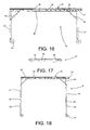
- Figures 16 and 18 are schematic side views of two alternative embodiments of the first covering structure 10.
- the uprights 21 have a fixed length
- the uprights are height-adjustable, since they have a telescopic structure with a plurality of predetermined levels 25 ( Figure 18).
- the height may be adjusted using any other method in addition to use of a telescopic structure.
- the uprights 21 can be fixed at different heights to angle the roof 15.
- the vehicle 2 also has at least a second compartment 26 in which the first covering structure 10 can be inserted when it is not used or when moving the apparatus 1.
- the first covering structure 10 may also be inserted directly in the first compartment 3, or may be transported using an auxiliary vehicle.
- the second compartment 26 extends in the upper part of the vehicle 2 above the first compartment 3 (as illustrated in the accompanying drawings), or at the side of the first compartment 3 (solution not illustrated), or below the floor of the first compartment 3 (this solution also not illustrated) .
- the first covering structure 10 can be moved between an open operating condition in which it can cover the platform 7 and a non-operating condition in which it is folded on itself (Figures 15 and 17). Folding of the first covering structure 10 involves folding the vertical uprights 21 which form the supporting legs under the crosspieces 22 which form the roof 15. Moreover, the frame 18 of the first covering structure 10 has at least one projecting upper portion 27 which can be inserted in the second compartment 26 when the first structure is in the operating condition.
- the latter has at least one insertion guide 28, whilst the first covering structure 10 has guide elements 29 (consisting of idle wheels) which can be coupled to the insertion guide 28.
- the side crosspieces 22 of the first supporting structure may also be fitted with a rack 30 designed to engage with a special motor-driven gear wheel (not illustrated) which allows the first covering structure 10 to be inserted in and removed from the second compartment 26 in an automated fashion.
- the frame 18 of the first covering structure 10 is rigid and can be directly drawn like a road trailer (by the vehicle 2 or by another vehicle).
- the first covering structure 10 is mounted on idle wheels 31 which allow it to be easily moved over the ground, but, to prevent accidental movements, it can also be made without wheels 31, or fitted with suitable supports (not illustrated) designed to lift the wheels 31 off the ground when the first covering structure 10 is assembled in the operating position.
- the apparatus 1 also comprises one or more stiffening elements 32 to lock the position of the covering structures relative to the vehicle 2 and/or to the lift 5 ( Figures 2 and 3).
- the second covering structure 11 in the preferred embodiment it has a bellows-style shape ( Figure 14), so that it can connect the vehicle 2 and the first covering structure 10, adjusting to their reciprocal position.
- the second covering structure 11 Since the second covering structure 11 is assembled between the vehicle 2 and the first covering structure 10, it can only be attached to them and be raised off the ground.
- the second covering structure 11 may have a rigid end 59 which can rest on the ground and be connected to the first covering structure 10 and a mobile end 60 which can be fixed to the vehicle 2 using belts 61.
- the vehicle 2 around the loading - unloading opening 4, the vehicle 2 has at least one seat 33 to which the second covering structure 11 is connected.
- the second covering structure 11 is mobile between an operating condition in which it is at least partly outside the seat 33 and can be connected to the first covering structure 10 using special hooks 34 ( Figure 14), and a travelling condition in which it is inserted in the seat 33 ( Figure 13).
- the temporary protective means 12 comprise at least one roll-up sheet 35 attached to the platform 7 and mobile between a home condition in which it is rolled up over itself ( Figures 24 and 25) and a covering condition in which it covers the platform 7.
- the platform 7 is also fitted with couplings 36 ( Figure 26) to hold the sheet 35 in the covering condition.
- the platform 7 comprises a loading surface 37 and a plurality of tilting side boards 38.
- the roll-up sheet 35 can be attached both to below the loading surface 37 ( Figure 24) and to a side board 38 ( Figure 25).
- the removal apparatus 1 disclosed may be completed with further accessory parts.
- auxiliary structure 39 which can be attached to the storey of the building 6 to which the lift 5 is connected (at the balcony 40 as illustrated in Figures 2 to 5, or to the window 41 as illustrated in Figures 6 and 7), with at least one coupling element 42 designed to hold the roll-up sheet 35 of the temporary protective means 12 in a loading - unloading condition in which it covers and protects the platform 7 but at the same time allows platform access.
- the auxiliary structure 39 comprises two vertical columns 43 with a plurality of coupling elements 42 positioned at different heights.
- the auxiliary structure 39 can, therefore, be adapted to any operating situation.
- auxiliary structure 39 also comprises a canopy 44 mounted in such a way that it projects on the vertical columns 43.
- Assembly of the apparatus 1 disclosed involves initially assembly of the lift 5 using the known methods, then positioning the vehicle 2 near the lift 5.
- the first covering structure 10 is positioned (if necessary preceded by its assembly) at the base of the lift 5.
- the first covering structure 10 is removed from the second compartment 26, manually or automatically ( Figures 9 - 12).
- the vertical uprights 21 are lowered relative to the roof 15 and fixed to the crosspieces 22 using the locking pistons 23 ( Figures 10 - 11).
- the projecting portion of the frame 18 is also taken out of the second compartment 26.
- the first covering structure 10 is then positioned above the platform 7 when the platform is in the lower position, and the roof 15 is, if necessary, opened and extended (and the relative crosspiece 24 is removed).
- the opening 4 in the roof 15 is only necessary when the lift 5 is assembled with a gradient greater than a predetermined limit.
- the first covering structure 10 is locked to the vehicle 2 and/or the lift 5 by means of the stiffening elements.
- the second covering structure 11 is then removed from its seat 33 and fixed to the first covering structure 10.
- auxiliary structure 39 may also be assembled, which can be attached to the balcony 40, or, using special clamps not illustrated, to the window 41 jambs.
- the furniture loaded on the platform 7 is covered by the temporary protective means 12 which, when the platform 7 is in the upper position, can be connected to the auxiliary structure 39 as illustrated in Figures 3, 4 and 7, so that its protection from the weather is guaranteed during unloading.
- the furniture can be covered either with nylon and sheets, or with special parts fitted on either the vehicle 2 or the lift 5.
- the covering panels 49 can move from the central position to the limit positions by means of manual or motor-driven mechanical operation, or, preferably, by impact of the platform 7 or the furniture loaded on them.
- the present invention brings important advantages.
- the apparatus disclosed guarantees protection against the weather both for the items to be moved and the removal men/women, along the entire path from the vehicle to the apartment.
- the apparatus can also be used to provide shade from the sun, for both the furniture or other delicate and valuable items, and for the removal workers, allowing them to operate in a more agreeable environment.
- the apparatus disclosed may be assembled even where space is limited and the vehicle cannot be positioned directly alongside the lift.
- the roll-up device 46 configuration of the temporary protective means in no way hinders access to the loading platform and allows them to be adjusted to any item transported, irrespective of its dimensions.
- the first covering structure guarantees shelter from the weather at the platform loading zone, that is to say, where, due to the need to correctly position the furniture, it is not possible to keep it covered even with nylon or sheets.
Landscapes
- Engineering & Computer Science (AREA)
- Structural Engineering (AREA)
- Transportation (AREA)
- Civil Engineering (AREA)
- Automation & Control Theory (AREA)
- Mechanical Engineering (AREA)
- Tents Or Canopies (AREA)
- Mechanical Treatment Of Semiconductor (AREA)
- Weting (AREA)
- Electrical Discharge Machining, Electrochemical Machining, And Combined Machining (AREA)
- Vehicle Cleaning, Maintenance, Repair, Refitting, And Outriggers (AREA)
Abstract
Description
- The present invention relates to a removal apparatus of the type described in the preamble of
claim 1. An apparatus of this kind is disclosed in JP 11342785. - The removal apparatuses used today consists of a transport vehicle inside which furniture and other items to be moved are transported, and a lift with a mobile platform that allows the furniture and other items to be transferred directly from the road, where the vehicle is parked, to the balcony or window of the apartment involved in the move, and vice versa.
- However, this known technology has the significant disadvantage of being greatly affected by the weather.
- In particular, in the event of precipitation, the move becomes quite problematic and in some cases impossible. It is essential that the furniture and other items (often packed in cardboard boxes) do not get wet, since they may be ruined.
- A variant is described in patent DE 3633505, which describes a loading platform having a removable rigid upper cover. However, this solution only guarantees protection from the rain for small furniture or other items and only when they are on the lift.
- In contrast, patent JP 11342785 describes a removal vehicle with canopies which can be pulled out of the side to cover the area next to the vehicle loading - unloading opening.
- However, that solution is not suitable for use with lifts, still less when the lift cannot be brought alongside the vehicle.
- In this situation, the technical need which forms the basis of the present invention is to provide a removal apparatus which is easy to use even in the event of precipitation, and which guarantees protection from the weather both for the items moved, irrespective of their size, and the removal operators.
- The technical need of the present invention is also to provide a removal apparatus which guarantees this result especially at the lift platform loading/unloading area.
- In particular, the technical need of the present invention is to provide a removal apparatus which guarantees this result substantially irrespective of the reciprocal position of the vehicle and the lift.
- The technical need specified and the aims indicated are substantially achieved by a removal apparatus as described in the claims herein.
- Further features and the advantages of the present invention, are more clearly illustrated in the detailed description which follows, with reference to the accompanying drawings, which illustrate several preferred examplary embodiments of a removal apparatus, without limiting the scope of the inventive concept, in which:
- Figure 1 is a schematic axonometric view of a removal apparatus according to the prior art;
- Figure 2 is a schematic axonometric view with some parts transparent, of a removal apparatus made according to the present invention, in a first operating situation;
- Figure 3 is a schematic axonometric view with some parts transparent and other duplicated, of a removal apparatus made according to the present invention, in a second operating situation;
- Figure 4 is a schematic axonometric view of a removal apparatus made according to the present invention, in a third operating situation;
- Figure 5 is a schematic axonometric view with some parts transparent, of a removal apparatus made according to the present invention, in another operating situation;
- Figure 6 is a schematic axonometric view with some parts transparent, of a removal apparatus made according to the present invention, in another operating situation;
- Figure 7 is a schematic axonometric view with some parts transparent, of a removal apparatus made according to the present invention, in another operating situation;
- Figure 8 is a schematic side view with some parts transparent and others cut away, of part of a removal apparatus made according to the present invention;
- Figures 9 to 12 are schematic side views with some parts transparent and others cut away, of the apparatus illustrated in Figure 8 during a sequence of assembly steps;
- Figure 13 is a schematic rear view of several details of a removal apparatus made according to the present invention;
- Figure 14 is a view of the apparatus illustrated in Figure 13 in the operating condition;
- Figure 15 is a schematic side view of a detail of the removal apparatus made according to the present invention;
- Figure 16 is a view of the detail illustrated in Figure 15 in the operating condition;
- Figure 17 is a rear view of the detail illustrated in Figure 15;
- Figure 18 is a view of an alternative embodiment of the detail illustrated in Figure 16;
- Figure 19 is a rear view of the detail illustrated in Figure 16;
- Figure 20 is a rear view of an alternative embodiment of the detail illustrated in Figure 19;
- Figures 21 and 22 are views of the detail illustrated in Figure 20 in different operating conditions;
- Figure 23 is a view of another alternative embodiment of the detail illustrated in Figure 16;
- Figures 24 and 25 illustrate two alternative embodiments of a platform which is part of the apparatus according to the present invention;
- Figure 26 is an axonometric view with some parts transparent of a platform which is part of the apparatus according to the present invention;
- Figure 27 is a schematic axonometric view, with some parts transparent, of another detail of the apparatus according to the present invention;
- Figure 28 is a side view of another part of the apparatus according to the present invention, in two operating conditions;
- Figure 29 is an axonometric top view of an alternative embodiment of a part of the apparatus illustrated in Figure 14;
- Figure 30 is an axonometric top view of an alternative embodiment of a part of the apparatus illustrated in Figure 12;
- Figure 31 is a schematic front axonometric view, with some parts cut away, of the structure illustrated in Figure 30 in a different operating condition;
- Figure 32 is a schematic front axonometric view, with some parts cut away, of the structure illustrated in Figure 31 in a different operating condition;
- Figure 33 is a schematic front axonometric view, with some parts cut away, of the structure illustrated in Figure 31 in a different operating condition;
- Figure 34 is a side view with some parts cut away of the structure illustrated in Figure 31;
- Figure 35 is a side view with some further parts visible of the structure illustrated in Figure 34 in a different operating condition;
- Figure 36 is a side view with further parts visible of the structure illustrated in Figure 34;
- Figure 37 is a side view of the structure illustrated in Figure 36 in the folded condition;
- Figure 38 is a schematic front axonometric view, with some parts cut away, of an alternative embodiment of the structure illustrated in Figure 31;
- Figure 39 is a schematic front axonometric view, with some parts cut away, of the structure illustrated in Figure 38 in a different operating condition;
- Figure 40 is a top view of a detail of the structure illustrated in Figures 38 and 39.
- With reference to the accompanying drawings, the
numeral 1 denotes as a whole a removal apparatus made according to the present invention. - In the most simple embodiment of the present invention, the
apparatus 1 comprises afirst covering structure 10 which can be fitted at a lower position of aplatform 7 of alift 5 to protect theplatform 7 from the weather when it is in the lower position. This first coveringstructure 10 is therefore designed to protect both items and people duringplatform 7 loading and unloading at ground level. - Details of the composition of the first covering
structure 10 are provided below, relative to the most complete embodiment of the present invention. - In the most complete embodiment, the
apparatus 1 comprises firstly avehicle 2, with at least afirst compartment 3 for transporting the items to be moved. Thisfirst compartment 3 can be accessed from the outside through at least one loading - unloadingopening 4, and atransportable lift 5, which can be assembled close to abuilding 6 and is equipped with atransport platform 7 mobile between a lower position in which it is close to the ground and an upper position in which it is at a predetermined storey of the building 6 (in Figure 3 theplatform 7 is represented simultaneously in both positions). The accompanying drawings illustrate alift 5 mounted on a drivingcarriage 8, of the conventional type. - The path along which the items to be moved are transferred, extending between the
vehicle 2 and theplatform 7 upper position, is fitted withspecial covering means 9 arranged in such a way as to cover the items to be moved along the entire path, protecting them from the weather. - Therefore, these covering means 9 comprise at least a first and a second covering
structure protective means 12 which can be attached to theplatform 7. - As already said, the first covering
structure 10 can be assembled at the base of thelift 5 so that it is over theplatform 7 when the platform is in the lower position, protecting it from the weather during loading - unloading operations. - In contrast, the
second covering structure 11 can be assembled between thefirst covering structure 10 and thevehicle 2 loading - unloadingopening 4, to create a covered path between thevehicle 2 and theplatform 7 when the platform is in the lower position. - In contrast, the temporary
protective means 12 are attached to theplatform 7 and are designed to cover it during movements between the lower position and the upper position. - In all of the embodiments illustrated in the accompanying drawings, the first covering
structure 10 has at least afirst side 13 which is open to allow the passage of theplatform 7, and at least asecond side 14 which is open (or can be opened) communicating with thesecond covering structure 11, which allows the transfer of the items to be moved between thevehicle 2 and theplatform 7 in the lower position and vice versa. - Advantageously, in the preferred embodiments, the first covering
structure 10 has, at the firstopen side 13, aroof 15 which can be at least partly lifted or opened to facilitate the passage of the platform 7 (Figures 4, 19 - 22, 30 - 40). - In particular, in the embodiments illustrated in Figures 4 and 19 - 22, the
roof 15 of the first coveringstructure 10 has afixed part 16 and amobile part 17 hinged to thefixed part 16 and which can be angled upwards relative to thefixed part 16. - Advantageously, the
mobile part 17 may also be angled downwards relative to the fixedpart 16. - In the most complete embodiment the
mobile part 17 of theroof 15 of thefirst covering structure 10, when in the angled position, can also be extended towards the outside of the first covering structure 10 (Figures 4 and 22). In the embodiment illustrated this is achieved with amobile part 17 configuration that is at least partly telescopic. - In contrast, in the embodiments illustrated in Figures 30 to 40, the
first covering structure 10 has aroof 15 which, at least at the firstopen side 13, can in turn be partly opened to facilitate the passage of theplatform 7. - In particular, the
roof 15 of thefirst covering structure 10 has a fixedpart 16 and amobile part 17. As illustrated in the accompanying drawings, the fixedpart 16 advantageously (but not necessarily) has a C-shaped plan, whilst themobile part 17 extends between the two arms of the C. - In the embodiment illustrated in Figures 30 to 37, the
mobile part 17 is mobile between an active position in which it closes anopening 45 of the roof 15 (Figure 30) and a withdrawn position in which it leaves theopening 45 clear (Figure 32) . - In particular, the
mobile part 17 advantageously consists of a roll-up device 46 (for example a sheet), designed to run, with its side edges, on the fixed part 16 (Figure 33). - Moreover, there may also be mobile supporting means 47 for the
mobile part 17 which support themobile part 17 in such a way that it projects outwards relative to thefirst covering structure 10. In the accompanying drawings the mobile means 47 consist of two pull-outattachments 48 mounted on the fixedpart 16. - In addition, in the preferred embodiment of the
first covering structure 10, the mobile part 17 (the sheet) is motor-driven. - There may also be control means (not illustrated) for the mobile part, operatively connected both to the
mobile part 17 motor (also not illustrated) and to special sensors (not illustrated) connected to thelift 5 and/or to thefirst covering structure 10. - In particular, the control means can be programmed to control the movement of the
mobile part 17 according to the position of theplatform 7, in such a way as to move themobile part 17 to the withdrawn position when theplatform 7 passes as it moves up or down. - As regards the sensors, in addition to sensors which detect the position of the
platform 7, there may be safety sensors designed to check that the dimensions of the items loaded on theplatform 7 do not exceed the dimensions of the part of theroof 15 which can be opened, to prevent accidental impact against the fixedpart 16. - In contrast, in the embodiment illustrated in Figures 38 to 40, the
mobile part 17 comprises one ormore covering panels 49, adjacent to one another and advantageously partly overlapping, to guarantee a seal against rain. - As illustrated in Figure 40, each covering
panel 49 is mounted on abar 50 which is in turn hinged to a supportingbeam 62 connected to the fixedpart 16. - In this way, each covering
panel 49 is hinged relative to the fixedpart 16 according to a horizontal axis of rotation, and is mobile between a central position in which it forms part of the roof 15 (Figures 38 and 39 in which only thebars 50 are illustrated), and two limit positions rotated respectively upwards and downwards relative to the central position (not illustrated) in which they allow theplatform 7 to pass. - Moreover, yielding supporting
means 51 are attached to each coveringpanel 49 to hold it in the central position, in the absence of external stresses. In the embodiment illustrated, these yielding supporting means 51 are in particular mounted between eachbar 50 and the supportingbeam 62, and comprise one or more spring-loadedhinges 52 which can rotate through approximately 90° about the central position of equilibrium. - When the dimensions of the mobile part 17 (that is to say, the length of the individual covering panels 49) are relatively large, each covering panel 49 (as well as the relative bar 50) can be divided into a plurality of
pieces 53, starting from the supportingbeam 62, each hinged to the previous one in the same way as the coveringpanel 49 as a whole is hinged relative to the fixedpart 16. Therefore, as illustrated in Figure 40, there is a spring-loadedhinge 52 between eachpiece 53. - Again in this embodiment, there may be mobile supporting means 47 for the
mobile part 17 which support themobile part 17 in such a way that it projects outwards relative to thefirst covering structure 10. In the accompanying drawings the mobile means 47 allow the supportingbeam 62 to move along twoside racks 54, parallel with the direction in which thebars 50 extend. - In this way, the supporting
beam 62 is mobile between a first limit position (Figure 38) in which the coveringpanels 49 are partly inserted inside the fixedpart 16, and a second limit position (Figure 39) in which the coveringpanels 49 are completely outside thefixed part 16. As a result, again in this case the covering panels 49 (as well as the bars 50) must be divided into at least twopieces 53 so that, even when the supportingbeam 62 is in the first position, at least one joint point is outside the fixed part, and therefore able to operate. - In the embodiments illustrated in Figures 4 and 19 - 22, the
first covering structure 10 consists of arigid frame 18 to which roll-upsheets 19 are attached which, once spread out cover its sides. Eachsheet 19 is mobile between a rolled up condition in which it is rolled over itself, and a spread out condition in which it covers at least part of aside wall 20 of thefirst covering structure 10. - In the accompanying drawings from 2 to 7, the
frame 18 has the shape of a parallelepiped and has at least two roll-upsheets 19, designed to cover at least twoside walls 20. - Alternatively, in the embodiment illustrated in Figures 30 to 40, the
first covering structure 10 comprises a plurality of sideprotective panels 55. Each sideprotective panel 55 is mobile between a first position in which it forms a closed side surface of the first structure (Figure 30), and a second position in which it allows passage through said side surface (relatively visible in Figure 37 where the structure is folded). - The side
protective panel 55 illustrated in Figures 35 and 36 consists of a framework 56 (Figure 35) covered by a sheet 57 (Figure 36), in which holes (not illustrated) may be cut to prevent the sideprotective panel 55 from behaving like a sail in the wind. - In the embodiment illustrated in Figure 30, the two side
protective panels 55 mounted on the short side of thefirst covering structure 10 may each be hinged to a leg (upright 21) of the first supportingstructure 10, and to the sideprotective panel 55 mounted on the long side (case illustrated). Alternatively, thepanels 55 may also be mounted in a removable fashion. - The side
protective panel 55 mounted on the long side may, for example, be mounted in a removable fashion, and be hinged to theroof 15 of the first covering structure 10 (case illustrated). - In all of the cases the
first covering structure 10 is also fitted with lockingelements 58 designed to hold the sideprotective panels 55 in position. - Moreover, in other embodiments the side
protective panels 55 consist of several parts connected in the appropriate way. - In the embodiments illustrated in the accompanying drawings, the
frame 18 of thefirst covering structure 10 has a plurality ofvertical uprights 21 andhorizontal crosspieces 22 connected to thevertical uprights 21, even usingspecial locking pistons 23. In the case of afirst covering structure 10 with aliftable roof 15, at least the crosspiece 24 at the firstopen side 13 is partly removable to allow the passage of the platform 7 (Figure 23). - In contrast, in the case of the first covering structure illustrated in Figure 30, the
horizontal crosspieces 22 are substituted by the fixedpart 16 of the roof which forms a single C-shaped body. - Figures 16 and 18 are schematic side views of two alternative embodiments of the
first covering structure 10. In the embodiment in Figure 16 theuprights 21 have a fixed length, whilst in the embodiment in Figure 18 the uprights are height-adjustable, since they have a telescopic structure with a plurality of predetermined levels 25 (Figure 18). However, the height may be adjusted using any other method in addition to use of a telescopic structure. - In the case of
adjustable uprights 21, advantageously theuprights 21 can be fixed at different heights to angle theroof 15. - In the preferred embodiment, the
vehicle 2 also has at least asecond compartment 26 in which thefirst covering structure 10 can be inserted when it is not used or when moving theapparatus 1. However, in some cases thefirst covering structure 10 may also be inserted directly in thefirst compartment 3, or may be transported using an auxiliary vehicle. - Advantageously, the
second compartment 26 extends in the upper part of thevehicle 2 above the first compartment 3 (as illustrated in the accompanying drawings), or at the side of the first compartment 3 (solution not illustrated), or below the floor of the first compartment 3 (this solution also not illustrated) . - In the embodiments illustrated, to facilitate its insertion in the
second compartment 26, thefirst covering structure 10 can be moved between an open operating condition in which it can cover theplatform 7 and a non-operating condition in which it is folded on itself (Figures 15 and 17). Folding of thefirst covering structure 10 involves folding thevertical uprights 21 which form the supporting legs under thecrosspieces 22 which form theroof 15. Moreover, theframe 18 of thefirst covering structure 10 has at least one projectingupper portion 27 which can be inserted in thesecond compartment 26 when the first structure is in the operating condition. - To facilitate the insertion and removal of the
first covering structure 10 in thesecond compartment 26, the latter has at least oneinsertion guide 28, whilst thefirst covering structure 10 has guide elements 29 (consisting of idle wheels) which can be coupled to theinsertion guide 28. - Moreover, the
side crosspieces 22 of the first supporting structure may also be fitted with arack 30 designed to engage with a special motor-driven gear wheel (not illustrated) which allows thefirst covering structure 10 to be inserted in and removed from thesecond compartment 26 in an automated fashion. - However, it should be noticed that there are also embodiments in which the
frame 18 of thefirst covering structure 10 is rigid and can be directly drawn like a road trailer (by thevehicle 2 or by another vehicle). - Finally, in the embodiments illustrated, the
first covering structure 10 is mounted onidle wheels 31 which allow it to be easily moved over the ground, but, to prevent accidental movements, it can also be made withoutwheels 31, or fitted with suitable supports (not illustrated) designed to lift thewheels 31 off the ground when thefirst covering structure 10 is assembled in the operating position. - To prevent unwanted movements of the first and
second covering structure 11, theapparatus 1 also comprises one ormore stiffening elements 32 to lock the position of the covering structures relative to thevehicle 2 and/or to the lift 5 (Figures 2 and 3). - As regards the
second covering structure 11, in the preferred embodiment it has a bellows-style shape (Figure 14), so that it can connect thevehicle 2 and thefirst covering structure 10, adjusting to their reciprocal position. - Since the
second covering structure 11 is assembled between thevehicle 2 and thefirst covering structure 10, it can only be attached to them and be raised off the ground. - Alternatively, as illustrated in Figure 29, the
second covering structure 11 may have arigid end 59 which can rest on the ground and be connected to thefirst covering structure 10 and amobile end 60 which can be fixed to thevehicle 2 usingbelts 61. In the preferred embodiment of the present invention, around the loading - unloadingopening 4, thevehicle 2 has at least oneseat 33 to which thesecond covering structure 11 is connected. Moreover, thesecond covering structure 11 is mobile between an operating condition in which it is at least partly outside theseat 33 and can be connected to thefirst covering structure 10 using special hooks 34 (Figure 14), and a travelling condition in which it is inserted in the seat 33 (Figure 13). - The temporary
protective means 12 comprise at least one roll-upsheet 35 attached to theplatform 7 and mobile between a home condition in which it is rolled up over itself (Figures 24 and 25) and a covering condition in which it covers theplatform 7. Theplatform 7 is also fitted with couplings 36 (Figure 26) to hold thesheet 35 in the covering condition. - As illustrated in Figures 24, 25 and 26, the
platform 7 comprises aloading surface 37 and a plurality of tiltingside boards 38. The roll-upsheet 35 can be attached both to below the loading surface 37 (Figure 24) and to a side board 38 (Figure 25). - The
removal apparatus 1 disclosed may be completed with further accessory parts. - For example, there may be an
auxiliary structure 39 which can be attached to the storey of thebuilding 6 to which thelift 5 is connected (at thebalcony 40 as illustrated in Figures 2 to 5, or to thewindow 41 as illustrated in Figures 6 and 7), with at least onecoupling element 42 designed to hold the roll-upsheet 35 of the temporaryprotective means 12 in a loading - unloading condition in which it covers and protects theplatform 7 but at the same time allows platform access. - In the embodiment in Figure 27 the
auxiliary structure 39 comprises twovertical columns 43 with a plurality ofcoupling elements 42 positioned at different heights. Theauxiliary structure 39 can, therefore, be adapted to any operating situation. - In addition, the
auxiliary structure 39 also comprises acanopy 44 mounted in such a way that it projects on thevertical columns 43. - Assembly of the
apparatus 1 disclosed involves initially assembly of thelift 5 using the known methods, then positioning thevehicle 2 near thelift 5. - Then the
first covering structure 10 is positioned (if necessary preceded by its assembly) at the base of thelift 5. - If required, before assembling the
first covering structure 10, thefirst covering structure 10 is removed from thesecond compartment 26, manually or automatically (Figures 9 - 12). In particular, as soon as possible thevertical uprights 21 are lowered relative to theroof 15 and fixed to thecrosspieces 22 using the locking pistons 23 (Figures 10 - 11). Finally, the projecting portion of theframe 18 is also taken out of thesecond compartment 26. - The
first covering structure 10 is then positioned above theplatform 7 when the platform is in the lower position, and theroof 15 is, if necessary, opened and extended (and therelative crosspiece 24 is removed). Theopening 4 in theroof 15 is only necessary when thelift 5 is assembled with a gradient greater than a predetermined limit. - At this point the
first covering structure 10 is locked to thevehicle 2 and/or thelift 5 by means of the stiffening elements. - In the most complete embodiment of the invention, the
second covering structure 11 is then removed from itsseat 33 and fixed to thefirst covering structure 10. - If necessary, the
auxiliary structure 39 may also be assembled, which can be attached to thebalcony 40, or, using special clamps not illustrated, to thewindow 41 jambs. - During the move, the furniture loaded on the
platform 7 is covered by the temporaryprotective means 12 which, when theplatform 7 is in the upper position, can be connected to theauxiliary structure 39 as illustrated in Figures 3, 4 and 7, so that its protection from the weather is guaranteed during unloading. - In the most simple embodiment of the present invention, both during transfer from the
vehicle 2 to thefirst covering structure 10, and during thelift 5 upward movement, the furniture can be covered either with nylon and sheets, or with special parts fitted on either thevehicle 2 or thelift 5. - The covering
panels 49 can move from the central position to the limit positions by means of manual or motor-driven mechanical operation, or, preferably, by impact of theplatform 7 or the furniture loaded on them. - The present invention brings important advantages.
- Firstly, the apparatus disclosed guarantees protection against the weather both for the items to be moved and the removal men/women, along the entire path from the vehicle to the apartment.
- Secondly, on summer days, the apparatus can also be used to provide shade from the sun, for both the furniture or other delicate and valuable items, and for the removal workers, allowing them to operate in a more agreeable environment.
- In addition the apparatus disclosed may be assembled even where space is limited and the vehicle cannot be positioned directly alongside the lift.
- Moreover, the roll-up
device 46 configuration of the temporary protective means in no way hinders access to the loading platform and allows them to be adjusted to any item transported, irrespective of its dimensions. - Even in the most simple embodiment, the first covering structure guarantees shelter from the weather at the platform loading zone, that is to say, where, due to the need to correctly position the furniture, it is not possible to keep it covered even with nylon or sheets.
- It should also be noticed that the present invention is relatively easy to make and even the cost linked to implementation of the invention is not very high.
- The invention described may be subject to many modifications and variations, without thereby departing from the scope of the appended claims.
- All details may be substituted by other technically equivalent elements and all materials used, as well as the shapes and dimensions of the various components, may be any according to requirements.
Claims (36)
- A removal apparatus comprising a vehicle (2) with at least a first compartment (3) for transporting items to be moved, and accessible from the outside at least through a loading - unloading opening (4), covering means (9) comprising at least a second covering structure associated to the vehicle (2) loading - unloading opening (4), the removal apparatus characterised in that it further comprises a transportable lift (5), which can be assembled close to a building (6), the lift having a transport platform (7) mobile between a lower position in which it is close to the ground and an upper position in which it is at a predetermined storey of the building (6), there also being a path for transferring the items to be moved extending between the vehicle (2) and the platform (7) upper position, said covering means being arrangeable in such a way that they cover the items to be moved along the entire path, protecting them from the weather, the covering means (9) further comprising:- at least a first covering structure (10) which can be assembled at the platform (7) lower position to protect the platform (7) from the weather when it is in the lower position; and- temporary protective means (12) which can be attached to the platform (7) to cover it during movements between the lower position and the upper position;the second covering structure (11) being assemblable between the first covering structure (10) and the vehicle (2) loading - unloading opening (4) to create a covered path between the vehicle (2) and the platform (7) in its lowered position, and in that the first covering structure (10) has a roof (15) which can be at least partly lifted or opened to facilitate the passage of the platform (7).
- The removal apparatus according to claim 1, characterised in that the first covering structure (10) has at least a first open side (13) to allow the passage of the platform (7), and at least a second open side (14) communicating with the second covering structure (11).
- The removal apparatus according to claim 2, characterised in that the roof (15) can be at least partly lifted to facilitate the passage of the platform (7) at the first open side (13).
- The removal apparatus according to claim 3, characterised in that the roof (15) of the first covering structure (10) has a fixed part (16) and a mobile part (17) hinged to the fixed part (16) which can be angled downwards and/or upwards relative to the fixed part (16).
- The removal apparatus according to claim 4, characterised in that in the angled position the portion of the mobile part (17) which is angled upwards is also extendable.
- The removal apparatus according to claim 5, characterised in that the mobile part (17) has a telescopic structure.
- The removal apparatus according to claim 1, characterised in that the roof (15) of the first covering structure (10) has a fixed part (16) and a mobile part (17).
- The removal apparatus according to claim 7, characterised in that the mobile part (17) is mobile between an active position in which it closes an opening (45) of the roof (15) and a withdrawn position in which it leaves the opening (45) clear.
- The removal apparatus according to either of the claims 7 and 8, characterised in that the mobile part (17) consists of a roll-up device (46).
- The removal apparatus according to any of the claims from 7 to 9, characterised in that the mobile part (17) is motor-driven.
- The removal apparatus according to claim 10, characterised in that the movement of the mobile part (17) is controlled according to the position of the platform (7), so as to move the mobile part into the withdrawn position when the platform (7) passes.
- The removal apparatus according to claim 7, characterised in that the mobile part (17) comprises one or more adjacent covering panels (49), each hinged relative to the fixed part (16) according to a horizontal axis of rotation, and mobile between a central position in which it forms part of the roof (15), and two limit positions rotated respectively upwards and downwards relative to the central position, in which it allows the passage of the platform (7).
- The removal apparatus according to claim 12, characterised in that the mobile part also comprises yielding supporting means (51) attached to each of the covering panels (49) to hold them in the central position in the absence of external stresses.
- The removal apparatus according to claim 13, characterised in that the yielding supporting means (51) comprise at least one spring-loaded hinge (52).
- The removal apparatus according to claim 12, 13 or 14, characterised in that each covering panel (49) is divided into a plurality of pieces (53), each hinged to the previous one in the same way as the covering panel (49) as a whole is hinged relative to the fixed part.
- The removal apparatus according to any of the claims from 7 to 15, characterised in that it comprises mobile supporting means (47) for the mobile part (17) which support the mobile part in such a way that it projects outwards relative to the first covering structure (10).
- The removal apparatus according to any of the claims from 2 to 16, characterised in that the first covering structure (10) has a plurality of vertical uprights (21) and horizontal crosspieces (22) connected to the vertical uprights (21), at least one of the crosspieces (22), (24), positioned at the first open side (13), being at least partly removable to facilitate the passage of the platform (7).
- The removal apparatus according to any of the previous claims, characterised in that the first covering structure (10) also comprises a plurality of roll-up sheets (19) for covering its sides.
- The removal apparatus according to claim 18, characterised in that each of the sheets (19) is mobile between a rolled up condition in which it is rolled up over itself and a spread out condition in which it forms a closed side surface of the first covering structure (10).
- The removal apparatus according to any of the claims from 1 to 17, characterised in that the first covering structure (10) also comprises a plurality of side protective panels (55).
- The removal apparatus according to claim 20, characterised in that each of the side protective panels (55) is mobile between a first position in which it forms a closed side surface of the first structure (10) and a second position in which it allows passage through the side surface.
- The removal apparatus according to any of the previous claims, characterised in that the vehicle (2) also has at least a second compartment (26) and characterised in that the first covering structure (10) can be inserted in the second compartment (26).
- The removal apparatus according to claim 22, characterised in that the first covering structure (10) can be moved between an operating condition in which it can cover the platform (7) and a non-operating condition in which it is folded over itself, and in which it can be inserted in the second compartment (26).
- The removal apparatus according to claim 22 or 23, characterised in that the second compartment (26) extends in the upper part of the vehicle (2), in a side part of the vehicle (2) or in a lower part of the vehicle (2).
- The removal apparatus according to claim 24, characterised in that the first covering structure (10) has at least one projecting upper portion (27) which can be inserted in the second compartment (26) when it is in the operating condition, it then being possible to bring the structure into the non-operating condition.
- The removal apparatus according to claim 24 or 25, characterised in that the second compartment (26) has at least one insertion guide (28) for guiding the insertion and removal of the first covering structure (10), and also characterised in that the first covering structure (10) has guide elements (29) which can be coupled to the insertion guide (28).
- The removal apparatus according to any of the previous claims, characterised in that the first covering structure (10) has a plurality of height-adjustable vertical supporting legs.
- The removal apparatus according to any of the previous claims, characterised in that the first covering structure (10) is mounted on idle wheels (31).
- The removal apparatus according to any of the previous claims, characterised in that it also comprises one or more stiffening elements (32) to lock the position of the covering structures relative to the vehicle (2) and/or relative to the lift (5).
- The removal apparatus according to any of the previous claims, characterised in that the second covering structure (11) has a bellows shape.
- The removal apparatus according to any of the claims from 1 to 29, characterised in that the second covering structure (11) has a rigid end (59) which can be connected to the first covering structure (10) and a mobile end (60) which can be fixed to the vehicle (2).
- The removal apparatus according to any of the previous claims, characterised in that the vehicle (2) has at least one seat (33) created around the loading - unloading opening (4), the second covering structure (11) being connected to the seat (33) and being mobile between an operating condition in which it is at least partly outside the seat (33) and can be connected to the first covering structure (10), and a travelling condition in which it is inserted in the seat (33).
- The removal apparatus according to any of the previous claims, characterised in that the temporary protective means (12) comprise at least one roll-up sheet (35) attachable to the platform (7) and movable between a home condition in which it is rolled up over itself and a covering condition in which it covers the platform (7), the platform (7) also being fitted with couplings (36) for holding the sheet (35) in the covering condition.
- The removal apparatus according to any of the previous claims, characterised in that it also comprises an auxiliary structure (39) which can be attached to the storey of the building (6) to which the lift (5) is connected when in use, the auxiliary structure (39) comprising at least one coupling element (42) to hold the temporary protective means (12) in a loading - unloading condition in which they cover the platform (7), at the same time allowing access to it.
- The removal apparatus according to claim 34, characterised in that the auxiliary structure (39) also comprises a canopy (44) to further protect the platform (7).
- A first covering structure (10) for a removal apparatus to be assembled at the lower position of a lift (5) platform (7) of the removal apparatus to protect the platform (7) from the weather when it is in the lower position, characterised in that the first covering structure (10) is made in accordance with any of the previous claims.
Applications Claiming Priority (2)
| Application Number | Priority Date | Filing Date | Title |
|---|---|---|---|
| ITVR20030118 | 2003-10-15 | ||
| IT000118A ITVR20030118A1 (en) | 2003-10-15 | 2003-10-15 | EQUIPMENT FOR REMOVALS. |
Publications (2)
| Publication Number | Publication Date |
|---|---|
| EP1548211A1 EP1548211A1 (en) | 2005-06-29 |
| EP1548211B1 true EP1548211B1 (en) | 2006-08-02 |
Family
ID=34531959
Family Applications (1)
| Application Number | Title | Priority Date | Filing Date |
|---|---|---|---|
| EP04023299A Not-in-force EP1548211B1 (en) | 2003-10-15 | 2004-09-30 | A removal apparatus |
Country Status (4)
| Country | Link |
|---|---|
| EP (1) | EP1548211B1 (en) |
| AT (1) | ATE335111T1 (en) |
| DE (1) | DE602004001749T2 (en) |
| IT (1) | ITVR20030118A1 (en) |
Family Cites Families (4)
| Publication number | Priority date | Publication date | Assignee | Title |
|---|---|---|---|---|
| GB2140479A (en) * | 1983-05-10 | 1984-11-28 | Guerrero Jesus Villa | Folding shelters |
| DE3633505A1 (en) * | 1985-10-10 | 1987-04-16 | Boecker Albert Gmbh & Co Kg | Load platform for inclined hoists |
| JPH11342785A (en) * | 1998-06-02 | 1999-12-14 | Kanto Giken:Kk | Truck for removal |
| DE20213307U1 (en) * | 2002-08-29 | 2002-10-24 | Hymer Idc Gmbh & Co Kg | Conversion kit for a motor vehicle and motor vehicle |
-
2003
- 2003-10-15 IT IT000118A patent/ITVR20030118A1/en unknown
-
2004
- 2004-09-30 AT AT04023299T patent/ATE335111T1/en not_active IP Right Cessation
- 2004-09-30 DE DE602004001749T patent/DE602004001749T2/en not_active Expired - Fee Related
- 2004-09-30 EP EP04023299A patent/EP1548211B1/en not_active Not-in-force
Also Published As
| Publication number | Publication date |
|---|---|
| DE602004001749T2 (en) | 2007-10-04 |
| DE602004001749D1 (en) | 2006-09-14 |
| ITVR20030118A1 (en) | 2005-04-16 |
| ATE335111T1 (en) | 2006-08-15 |
| EP1548211A1 (en) | 2005-06-29 |
Similar Documents
| Publication | Publication Date | Title |
|---|---|---|
| US4635412A (en) | Folding house transportable in the form of a stackable container | |
| US5862827A (en) | Mobile and adjustable elevated platform | |
| CA1325032C (en) | Annexe | |
| US5237784A (en) | Shelter container fit for habitation with extendible inner volume | |
| US3737190A (en) | Camper unit | |
| IE60765B1 (en) | Transportable construction element in the form of a container | |
| US20160096465A1 (en) | Railing system, particularly for travel trailers | |
| GB1572352A (en) | Vehicle body | |
| CA2110348A1 (en) | Container of variable volume | |
| WO2017042575A1 (en) | Raising roofs for vehicles | |
| AU2021300880B2 (en) | Automotive cargo/tray cover assembly | |
| US20220097593A1 (en) | Vehicle Mounted Enclosure | |
| KR20200125161A (en) | Loof top cover type vehicle | |
| KR102403573B1 (en) | Roof top tent for vehicle | |
| EP1363804B1 (en) | Sheltered aircraft supply vehicle | |
| EP1548211B1 (en) | A removal apparatus | |
| US3254657A (en) | Camping device and method | |
| US3259422A (en) | Sleeper unit for station wagons and the like | |
| US2806478A (en) | Collapsible shelter device for motor vehicles | |
| CN109383360A (en) | A kind of roof has the caravan in extendible space | |
| US20210371016A1 (en) | Rack System for Pickup Trucks | |
| US3078117A (en) | Camping and touring trailer | |
| RU223175U1 (en) | Vehicle body transformable into stage | |
| EP0881112A1 (en) | Integrated system for large-volume containers and transport means | |
| CN218623633U (en) | Roof tent and vehicle |
Legal Events
| Date | Code | Title | Description |
|---|---|---|---|
| PUAI | Public reference made under article 153(3) epc to a published international application that has entered the european phase |
Free format text: ORIGINAL CODE: 0009012 |
|
| AK | Designated contracting states |
Kind code of ref document: A1 Designated state(s): AT BE BG CH CY CZ DE DK EE ES FI FR GB GR HU IE IT LI LU MC NL PL PT RO SE SI SK TR |
|
| AX | Request for extension of the european patent |
Extension state: AL HR LT LV MK |
|
| 17P | Request for examination filed |
Effective date: 20050511 |
|
| GRAP | Despatch of communication of intention to grant a patent |
Free format text: ORIGINAL CODE: EPIDOSNIGR1 |
|
| AKX | Designation fees paid |
Designated state(s): AT BE BG CH CY CZ DE DK EE ES FI FR GB GR HU IE IT LI LU MC NL PL PT RO SE SI SK TR |
|
| RIC1 | Information provided on ipc code assigned before grant |
Ipc: E04H 15/00 20060101AFI20060221BHEP Ipc: B60P 1/00 20060101ALI20060221BHEP |
|
| GRAS | Grant fee paid |
Free format text: ORIGINAL CODE: EPIDOSNIGR3 |
|
| GRAA | (expected) grant |
Free format text: ORIGINAL CODE: 0009210 |
|
| AK | Designated contracting states |
Kind code of ref document: B1 Designated state(s): AT BE BG CH CY CZ DE DK EE ES FI FR GB GR HU IE IT LI LU MC NL PL PT RO SE SI SK TR |
|
| PG25 | Lapsed in a contracting state [announced via postgrant information from national office to epo] |
Ref country code: RO Free format text: LAPSE BECAUSE OF FAILURE TO SUBMIT A TRANSLATION OF THE DESCRIPTION OR TO PAY THE FEE WITHIN THE PRESCRIBED TIME-LIMIT Effective date: 20060802 Ref country code: PL Free format text: LAPSE BECAUSE OF FAILURE TO SUBMIT A TRANSLATION OF THE DESCRIPTION OR TO PAY THE FEE WITHIN THE PRESCRIBED TIME-LIMIT Effective date: 20060802 Ref country code: NL Free format text: LAPSE BECAUSE OF FAILURE TO SUBMIT A TRANSLATION OF THE DESCRIPTION OR TO PAY THE FEE WITHIN THE PRESCRIBED TIME-LIMIT Effective date: 20060802 Ref country code: SK Free format text: LAPSE BECAUSE OF FAILURE TO SUBMIT A TRANSLATION OF THE DESCRIPTION OR TO PAY THE FEE WITHIN THE PRESCRIBED TIME-LIMIT Effective date: 20060802 Ref country code: SI Free format text: LAPSE BECAUSE OF FAILURE TO SUBMIT A TRANSLATION OF THE DESCRIPTION OR TO PAY THE FEE WITHIN THE PRESCRIBED TIME-LIMIT Effective date: 20060802 Ref country code: BE Free format text: LAPSE BECAUSE OF FAILURE TO SUBMIT A TRANSLATION OF THE DESCRIPTION OR TO PAY THE FEE WITHIN THE PRESCRIBED TIME-LIMIT Effective date: 20060802 Ref country code: AT Free format text: LAPSE BECAUSE OF FAILURE TO SUBMIT A TRANSLATION OF THE DESCRIPTION OR TO PAY THE FEE WITHIN THE PRESCRIBED TIME-LIMIT Effective date: 20060802 Ref country code: CZ Free format text: LAPSE BECAUSE OF FAILURE TO SUBMIT A TRANSLATION OF THE DESCRIPTION OR TO PAY THE FEE WITHIN THE PRESCRIBED TIME-LIMIT Effective date: 20060802 Ref country code: LI Free format text: LAPSE BECAUSE OF FAILURE TO SUBMIT A TRANSLATION OF THE DESCRIPTION OR TO PAY THE FEE WITHIN THE PRESCRIBED TIME-LIMIT Effective date: 20060802 Ref country code: CH Free format text: LAPSE BECAUSE OF FAILURE TO SUBMIT A TRANSLATION OF THE DESCRIPTION OR TO PAY THE FEE WITHIN THE PRESCRIBED TIME-LIMIT Effective date: 20060802 Ref country code: FI Free format text: LAPSE BECAUSE OF FAILURE TO SUBMIT A TRANSLATION OF THE DESCRIPTION OR TO PAY THE FEE WITHIN THE PRESCRIBED TIME-LIMIT Effective date: 20060802 |
|
| REG | Reference to a national code |
Ref country code: GB Ref legal event code: FG4D |
|
| REG | Reference to a national code |
Ref country code: CH Ref legal event code: EP |
|
| REG | Reference to a national code |
Ref country code: IE Ref legal event code: FG4D |
|
| REF | Corresponds to: |
Ref document number: 602004001749 Country of ref document: DE Date of ref document: 20060914 Kind code of ref document: P |
|
| PG25 | Lapsed in a contracting state [announced via postgrant information from national office to epo] |
Ref country code: MC Free format text: LAPSE BECAUSE OF NON-PAYMENT OF DUE FEES Effective date: 20060930 |
|
| PG25 | Lapsed in a contracting state [announced via postgrant information from national office to epo] |
Ref country code: SE Free format text: LAPSE BECAUSE OF FAILURE TO SUBMIT A TRANSLATION OF THE DESCRIPTION OR TO PAY THE FEE WITHIN THE PRESCRIBED TIME-LIMIT Effective date: 20061102 Ref country code: DK Free format text: LAPSE BECAUSE OF FAILURE TO SUBMIT A TRANSLATION OF THE DESCRIPTION OR TO PAY THE FEE WITHIN THE PRESCRIBED TIME-LIMIT Effective date: 20061102 Ref country code: BG Free format text: LAPSE BECAUSE OF FAILURE TO SUBMIT A TRANSLATION OF THE DESCRIPTION OR TO PAY THE FEE WITHIN THE PRESCRIBED TIME-LIMIT Effective date: 20061102 |
|
| PG25 | Lapsed in a contracting state [announced via postgrant information from national office to epo] |
Ref country code: ES Free format text: LAPSE BECAUSE OF FAILURE TO SUBMIT A TRANSLATION OF THE DESCRIPTION OR TO PAY THE FEE WITHIN THE PRESCRIBED TIME-LIMIT Effective date: 20061113 |
|
| NLV1 | Nl: lapsed or annulled due to failure to fulfill the requirements of art. 29p and 29m of the patents act | ||
| PG25 | Lapsed in a contracting state [announced via postgrant information from national office to epo] |
Ref country code: PT Free format text: LAPSE BECAUSE OF FAILURE TO SUBMIT A TRANSLATION OF THE DESCRIPTION OR TO PAY THE FEE WITHIN THE PRESCRIBED TIME-LIMIT Effective date: 20070102 |
|
| REG | Reference to a national code |
Ref country code: CH Ref legal event code: PL |
|
| ET | Fr: translation filed | ||
| PLBE | No opposition filed within time limit |
Free format text: ORIGINAL CODE: 0009261 |
|
| STAA | Information on the status of an ep patent application or granted ep patent |
Free format text: STATUS: NO OPPOSITION FILED WITHIN TIME LIMIT |
|
| 26N | No opposition filed |
Effective date: 20070503 |
|
| PGFP | Annual fee paid to national office [announced via postgrant information from national office to epo] |
Ref country code: DE Payment date: 20071004 Year of fee payment: 4 |
|
| PG25 | Lapsed in a contracting state [announced via postgrant information from national office to epo] |
Ref country code: GR Free format text: LAPSE BECAUSE OF FAILURE TO SUBMIT A TRANSLATION OF THE DESCRIPTION OR TO PAY THE FEE WITHIN THE PRESCRIBED TIME-LIMIT Effective date: 20061103 |
|
| PGFP | Annual fee paid to national office [announced via postgrant information from national office to epo] |
Ref country code: FR Payment date: 20070928 Year of fee payment: 4 |
|
| PG25 | Lapsed in a contracting state [announced via postgrant information from national office to epo] |
Ref country code: EE Free format text: LAPSE BECAUSE OF FAILURE TO SUBMIT A TRANSLATION OF THE DESCRIPTION OR TO PAY THE FEE WITHIN THE PRESCRIBED TIME-LIMIT Effective date: 20060802 |
|
| PG25 | Lapsed in a contracting state [announced via postgrant information from national office to epo] |
Ref country code: HU Free format text: LAPSE BECAUSE OF FAILURE TO SUBMIT A TRANSLATION OF THE DESCRIPTION OR TO PAY THE FEE WITHIN THE PRESCRIBED TIME-LIMIT Effective date: 20070203 Ref country code: TR Free format text: LAPSE BECAUSE OF FAILURE TO SUBMIT A TRANSLATION OF THE DESCRIPTION OR TO PAY THE FEE WITHIN THE PRESCRIBED TIME-LIMIT Effective date: 20060802 Ref country code: LU Free format text: LAPSE BECAUSE OF NON-PAYMENT OF DUE FEES Effective date: 20060930 |
|
| PG25 | Lapsed in a contracting state [announced via postgrant information from national office to epo] |
Ref country code: CY Free format text: LAPSE BECAUSE OF FAILURE TO SUBMIT A TRANSLATION OF THE DESCRIPTION OR TO PAY THE FEE WITHIN THE PRESCRIBED TIME-LIMIT Effective date: 20060802 |
|
| GBPC | Gb: european patent ceased through non-payment of renewal fee |
Effective date: 20080930 |
|
| REG | Reference to a national code |
Ref country code: FR Ref legal event code: ST Effective date: 20090529 |
|
| PG25 | Lapsed in a contracting state [announced via postgrant information from national office to epo] |
Ref country code: IE Free format text: LAPSE BECAUSE OF NON-PAYMENT OF DUE FEES Effective date: 20080930 |
|
| PG25 | Lapsed in a contracting state [announced via postgrant information from national office to epo] |
Ref country code: DE Free format text: LAPSE BECAUSE OF NON-PAYMENT OF DUE FEES Effective date: 20090401 Ref country code: IT Free format text: LAPSE BECAUSE OF NON-PAYMENT OF DUE FEES Effective date: 20080930 |
|
| PGFP | Annual fee paid to national office [announced via postgrant information from national office to epo] |
Ref country code: IE Payment date: 20071011 Year of fee payment: 4 |
|
| PG25 | Lapsed in a contracting state [announced via postgrant information from national office to epo] |
Ref country code: FR Free format text: LAPSE BECAUSE OF NON-PAYMENT OF DUE FEES Effective date: 20080930 |
|
| PGFP | Annual fee paid to national office [announced via postgrant information from national office to epo] |
Ref country code: IT Payment date: 20070930 Year of fee payment: 4 |
|
| PG25 | Lapsed in a contracting state [announced via postgrant information from national office to epo] |
Ref country code: GB Free format text: LAPSE BECAUSE OF NON-PAYMENT OF DUE FEES Effective date: 20080930 |