EP1548162A2 - Drafting apparatus with fiber feeding means having longer service lifetime - Google Patents
Drafting apparatus with fiber feeding means having longer service lifetime Download PDFInfo
- Publication number
- EP1548162A2 EP1548162A2 EP04027376A EP04027376A EP1548162A2 EP 1548162 A2 EP1548162 A2 EP 1548162A2 EP 04027376 A EP04027376 A EP 04027376A EP 04027376 A EP04027376 A EP 04027376A EP 1548162 A2 EP1548162 A2 EP 1548162A2
- Authority
- EP
- European Patent Office
- Prior art keywords
- endless belt
- feeding means
- pair
- fiber
- drafting apparatus
- Prior art date
- Legal status (The legal status is an assumption and is not a legal conclusion. Google has not performed a legal analysis and makes no representation as to the accuracy of the status listed.)
- Withdrawn
Links
Images


Classifications
-
- D—TEXTILES; PAPER
- D01—NATURAL OR MAN-MADE THREADS OR FIBRES; SPINNING
- D01H—SPINNING OR TWISTING
- D01H5/00—Drafting machines or arrangements ; Threading of roving into drafting machine
- D01H5/18—Drafting machines or arrangements without fallers or like pinned bars
- D01H5/70—Constructional features of drafting elements
- D01H5/86—Aprons; Apron supports; Apron tensioning arrangements
-
- D—TEXTILES; PAPER
- D01—NATURAL OR MAN-MADE THREADS OR FIBRES; SPINNING
- D01H—SPINNING OR TWISTING
- D01H5/00—Drafting machines or arrangements ; Threading of roving into drafting machine
- D01H5/18—Drafting machines or arrangements without fallers or like pinned bars
- D01H5/26—Drafting machines or arrangements without fallers or like pinned bars in which fibres are controlled by one or more endless aprons
Definitions
- This invention concerns a drafting apparatus constructed in a way such that a fiber bundle is transported to the downstream side while stretched, and particularly, to improvement on fiber feeding means in the drafting apparatus.
- a drafting apparatus As well known, a drafting apparatus, as shown in Fig. 3, has been installed in a yarn manufacturing machine such as a spinning machine constituted of a drafting apparatus D and a spinning member S downstream thereof and besides in a fiber processing machine such as a roving machine and a slivering machine.
- the drafting apparatus D in a spinning machine as an example thereof includes : plural pairs of drafting rollers, which constitutes pairs of fiber feeding means.
- the drafting rollers are for use in drafting a sliver F and constituted of, for example, a pair of front rollers Rf, a pair of second rollers R2 having aprons, a pair of third rollers R3 and a pair of back rollers Rb.
- the invention has been made in order to solve the problem of the prior art and it is an object of the invention to provide a drafting apparatus, one of a pair of fiber feeding means constituting which is formed with an endless belt as an especially important element to thereby achieve a longer lifetime in service of a front roller Rf, to realize labor-saving in spinning operation and to improve an operation efficiency.
- the invention set forth in claim 2 is the drafting apparatus set forth in claim 1, characterized in that a tension is imparted to the endless belt in state of being wound around at least two pulleys, one of the at least two pulleys works to bring the endless belt into contact with the nip point so as to form the nip point, the at least two pulleys are disposed so that a direction in which the endless belt extends between the at least two pulleys intersects with a direction in which the fiber bundle is fed and the endless belt is wound around the at least two pulleys.
- Fig. 1 is a side view schematically showing a main section of a spinning machine combined with a drafting apparatus according to the invention.
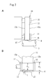
- Figs. 2 A and 2B show an example of the drafting apparatus in which an endless belt is applied to the top side of a pair of a first feeding means Rf, wherein Fig. 2A is a plan view schematically showing a main portion thereof and Fig. 2B is a cross sectional view of part of the endless belt together with related portions thereof.
- the endless belt means 11 in the pair of first feed means Rf includes the endless belt 12 and at least two pulleys 14 and 15 and a tension is imparted to the endless belt 12 in a state of being wound around the at least two pulleys 14 and 15.
- the pulley 14 brings the endless belt 12 into contact with the nip point N so as to form the nip point N, which can be realized with a configuration in which a line EL in a direction in which the endless belt means 11 spanned over the two pulleys extends intersects with a direction FD in which the fiber bundle is fed.
- plural pairs of fiber feeding means include: a pair of first feeding means Rf; a pair of second feeding means R2 having aprons; a pair of third feeding means R3 and a pair of fourth feeding means Rb in the order from the downstream side, wherein each of the pairs of second, third and fourth feeding means R2, R3 and Rb are constituted of a top roller 2 and bottom roller 3 combined and the pair of first feeding means Rf is constituted of the endless belt means 11 and a bottom roller 3 combined.
- Each of these pairs of fiber feeding means is higher in speed toward the downstream side.
- the endless belt 12 is composed of a pair of fiber feeding means having the highest fiber feed speed in the most downstream side, that is disposed in the pair of first feeding means Rf.
- a sliver F is drafted through the front roller Rf, the second roller R2 and the third roller R3, thereafter, guided into an air nozzle S1 and a pair of twisting rollers T constituting a spinning member S and a fiber bundle is twisted by a cooperative action of the air nozzle S1 and the twisting rollers T.
- a twisting efficiency of the combination is high with the result that a yarn can be spun at a high speed (200 m/min or higher).
- the effect of a longer lifetime in service in the invention is more conspicuous with a higher spinning speed, that is with a higher feed speed of the drafting apparatus D.
- a pulley 14 for bringing the endless belt 12 into contact with the nip point N has the protrusions 16 and 17 formed outwardly from the both ends 12a and 12a of the endless belt 12 in the width direction thereof and the level difference portions d are formed between each of the protrusions 16 and 17, and the contact portion at the nip point N of the endless belt 12. That is, if an outer diameter of the pulley 14 is set to ⁇ 1, an outer diameter of the protrusions 16 and 17 is set to ⁇ 2 and a thickness of the endless belt 12 is set to t by definition, the level difference portions d are formed if setting is made so as to establish a relation of [ ( ⁇ 2 - ⁇ 1) /2] ⁇ t.
- a drafting apparatus D related to the invention is applied to a spinning machine using a vortex air stream
- the invention is not limited the this application and can also applied to any of fiber processing machines each installed with a drafting apparatus such as a roving machine, slivering machine and a ring fine spinning machine.
- one of the pair of the fiber feeding means is constituted of an endless belt to thereby enable a longer lifetime in service of the fiber feeding means to be realized; thereby enabling the desired object to be achieved.
Landscapes
- Engineering & Computer Science (AREA)
- Mechanical Engineering (AREA)
- Textile Engineering (AREA)
- Spinning Or Twisting Of Yarns (AREA)
Abstract
Description
Claims (6)
- A drafting apparatus including a pair of fiber feeding means for transporting a fiber bundle to the downstream side while grasping the fiber bundle at a nip point and stretching it, characterized in that one of the pair of fiber feeding means is constituted of an endless belt, and the pair of fiber feeding means is provided so that a feeding force acting in a direction of feeding the fiber bundle with the endless belt is concentrated on the nip point.
- The drafting apparatus set forth in claim 1, characterized in that a tension is imparted to the endless belt in state of being wound around at least two pulleys, one of the at least two pulleys works to bring the endless belt into contact with the nip point so as to form the nip point, the at least two pulleys are disposed so that a direction in which the endless belt extends between the at least two pulleys intersects with a direction in which the fiber bundle is fed and the endless belt is wound around the at least two pulleys.
- The drafting apparatus set forth in claim 1 or 2, characterized in that plural pairs of feeding means thereof provided so as to be higher in feed speed of a pair of feeding means toward the downstream, wherein the endless belt is disposed in a pair of fiber feeding means having the highest fiber feed speed in the most downstream side.
- The drafting apparatus set forth in claim 3, characterized in that the pulley for bringing the endless belt into contact with the nip point has protrusions formed outwardly from the both ends of the endless belt in the width direction thereof and level difference portions are formed between the protrusions and a contact portion at the nip point of the endless belt.
- The drafting apparatus set forth in any one of claims 1 to 4, characterized in that the pair of fiber feeding means one of which is constituted of an endless belt is used in a spinning machine installed with a spinning member twisting a drafted fiber bundle with the action of a vortex air stream thereon.
- The drafting apparatus set forth in claim 5, characterized in that the spinning member is constituted of an air-spin nozzle generating a vortex air stream and a hollow guide shaft having a passage for a produced yarn.
Applications Claiming Priority (2)
| Application Number | Priority Date | Filing Date | Title |
|---|---|---|---|
| JP2003424665 | 2003-12-22 | ||
| JP2003424665A JP2005179857A (en) | 2003-12-22 | 2003-12-22 | Drafting device |
Publications (2)
| Publication Number | Publication Date |
|---|---|
| EP1548162A2 true EP1548162A2 (en) | 2005-06-29 |
| EP1548162A3 EP1548162A3 (en) | 2006-12-20 |
Family
ID=34544929
Family Applications (1)
| Application Number | Title | Priority Date | Filing Date |
|---|---|---|---|
| EP04027376A Withdrawn EP1548162A3 (en) | 2003-12-22 | 2004-11-18 | Drafting apparatus with fiber feeding means having longer service lifetime |
Country Status (3)
| Country | Link |
|---|---|
| EP (1) | EP1548162A3 (en) |
| JP (1) | JP2005179857A (en) |
| CN (1) | CN1637179A (en) |
Cited By (2)
| Publication number | Priority date | Publication date | Assignee | Title |
|---|---|---|---|---|
| WO2007101742A1 (en) * | 2006-03-08 | 2007-09-13 | Deutsche Institute für Textil- und Faserforschung Stuttgart | Wearing coating for delivery rollers of a drawing roller frame |
| WO2010016808A1 (en) * | 2008-08-04 | 2010-02-11 | Ozdilek Alisveris Merkezleri Ve Tekstil Sanayi Anonim Sirketi | Compact yarn manufacturing system |
Families Citing this family (2)
| Publication number | Priority date | Publication date | Assignee | Title |
|---|---|---|---|---|
| JP2012117181A (en) * | 2010-12-03 | 2012-06-21 | Toyota Industries Corp | Draft machine for drawing process |
| CN104963051B (en) * | 2015-07-09 | 2018-03-13 | 上海兰邦工业纤维有限公司 | Mechanical compact spinning manufacture aramid fiber yarn and its method, apparatus of aramid fiber covering yarn and the aramid fiber covering yarn of preparation |
Family Cites Families (3)
| Publication number | Priority date | Publication date | Assignee | Title |
|---|---|---|---|---|
| DE816069C (en) * | 1950-03-08 | 1951-10-08 | Deutscher Spinnereimaschb Ingo | Drafting system for spinning machines |
| GB1184787A (en) * | 1960-11-20 | 1970-03-18 | Mackie & Sons Ltd J | Improvements relating to Textile Drafting Apparatus |
| DE10260025A1 (en) * | 2002-12-19 | 2004-07-08 | Deutsche Institute für Textil- und Faserforschung (DITF) | Coating for drafting rollers |
-
2003
- 2003-12-22 JP JP2003424665A patent/JP2005179857A/en active Pending
-
2004
- 2004-11-18 EP EP04027376A patent/EP1548162A3/en not_active Withdrawn
- 2004-12-22 CN CN 200410103731 patent/CN1637179A/en active Pending
Cited By (3)
| Publication number | Priority date | Publication date | Assignee | Title |
|---|---|---|---|---|
| WO2007101742A1 (en) * | 2006-03-08 | 2007-09-13 | Deutsche Institute für Textil- und Faserforschung Stuttgart | Wearing coating for delivery rollers of a drawing roller frame |
| US8099835B2 (en) | 2006-03-08 | 2012-01-24 | Deutsche Institute fur Textile-und Faserforschung Stuttgart | Wearing coating for delivery rollers of a drawing roller frame |
| WO2010016808A1 (en) * | 2008-08-04 | 2010-02-11 | Ozdilek Alisveris Merkezleri Ve Tekstil Sanayi Anonim Sirketi | Compact yarn manufacturing system |
Also Published As
| Publication number | Publication date |
|---|---|
| EP1548162A3 (en) | 2006-12-20 |
| CN1637179A (en) | 2005-07-13 |
| JP2005179857A (en) | 2005-07-07 |
Similar Documents
| Publication | Publication Date | Title |
|---|---|---|
| JP3503704B2 (en) | Draft fiber strand bundling device | |
| JP3657314B2 (en) | Spinning method and spinning machine | |
| US6318060B1 (en) | Method and spinning machine for the production of core yarn | |
| US6131383A (en) | Spinning machine having a drafting frame provided with a suction roller | |
| US6185790B1 (en) | Arrangement for condensing a drafted fiber strand | |
| US6131382A (en) | Method of and apparatus for making a mock yarn | |
| US6209303B1 (en) | Arrangement and method for spinning a yarn | |
| CN1602373A (en) | Stretching machines for endless textile machines with fiber belt compressors | |
| JP2000073224A (en) | Spinning machinery having a plural number of spinning stations | |
| US4718225A (en) | Pneumatic spinning machine | |
| JP2007506007A (en) | Manufacturing method and manufacturing apparatus for core yarn or core strand | |
| CN1298904C (en) | Spinning machine for producing core-spun yarn | |
| EP1548162A2 (en) | Drafting apparatus with fiber feeding means having longer service lifetime | |
| US6298523B1 (en) | Apparatus for condensing a fiber strand and a method of making yarn using same | |
| CN1589342A (en) | Device on a spinning machine for compacting a fibre assembly | |
| JP2004512434A (en) | Spinner equipment for condensing fiber strands | |
| JP2003313735A (en) | Spinner equipment for condensing fiber strands | |
| US6338183B1 (en) | Arrangement for condensing a fiber strand | |
| EP2072647B1 (en) | Draft roller | |
| JP2003313734A (en) | Apparatus for producing mock ply yarn | |
| CN112760765B (en) | Cotton condenser for a drafting system of a spinning machine and drafting system of a cotton condenser | |
| JP2002235252A (en) | Assembly for spinning machines for condensing fiber strands | |
| Kumar et al. | Compact spinning: a critical review | |
| US7076840B2 (en) | Draft device | |
| JP5398948B2 (en) | Method and apparatus for manufacturing a core yarn |
Legal Events
| Date | Code | Title | Description |
|---|---|---|---|
| PUAI | Public reference made under article 153(3) epc to a published international application that has entered the european phase |
Free format text: ORIGINAL CODE: 0009012 |
|
| AK | Designated contracting states |
Kind code of ref document: A2 Designated state(s): AT BE BG CH CY CZ DE DK EE ES FI FR GB GR HU IE IS IT LI LU MC NL PL PT RO SE SI SK TR |
|
| AX | Request for extension of the european patent |
Extension state: AL HR LT LV MK YU |
|
| PUAL | Search report despatched |
Free format text: ORIGINAL CODE: 0009013 |
|
| AK | Designated contracting states |
Kind code of ref document: A3 Designated state(s): AT BE BG CH CY CZ DE DK EE ES FI FR GB GR HU IE IS IT LI LU MC NL PL PT RO SE SI SK TR |
|
| AX | Request for extension of the european patent |
Extension state: AL HR LT LV MK YU |
|
| AKX | Designation fees paid |
Designated state(s): CH DE LI |
|
| STAA | Information on the status of an ep patent application or granted ep patent |
Free format text: STATUS: THE APPLICATION IS DEEMED TO BE WITHDRAWN |
|
| 18D | Application deemed to be withdrawn |
Effective date: 20070621 |