EP1547503A1 - Scheibenrandstütze - Google Patents
Scheibenrandstütze Download PDFInfo
- Publication number
- EP1547503A1 EP1547503A1 EP04257709A EP04257709A EP1547503A1 EP 1547503 A1 EP1547503 A1 EP 1547503A1 EP 04257709 A EP04257709 A EP 04257709A EP 04257709 A EP04257709 A EP 04257709A EP 1547503 A1 EP1547503 A1 EP 1547503A1
- Authority
- EP
- European Patent Office
- Prior art keywords
- channel
- sheet
- assembly according
- protector
- edge
- Prior art date
- Legal status (The legal status is an assumption and is not a legal conclusion. Google has not performed a legal analysis and makes no representation as to the accuracy of the status listed.)
- Withdrawn
Links
Images


Classifications
-
- A—HUMAN NECESSITIES
- A47—FURNITURE; DOMESTIC ARTICLES OR APPLIANCES; COFFEE MILLS; SPICE MILLS; SUCTION CLEANERS IN GENERAL
- A47K—SANITARY EQUIPMENT; ACCESSORIES THEREFOR, e.g. TOILET ACCESSORIES
- A47K3/00—Baths; Showers; Appurtenances therefor
- A47K3/28—Showers or bathing douches
- A47K3/30—Screens or collapsible cabinets for showers or baths
- A47K3/36—Articulated screens
-
- A—HUMAN NECESSITIES
- A47—FURNITURE; DOMESTIC ARTICLES OR APPLIANCES; COFFEE MILLS; SPICE MILLS; SUCTION CLEANERS IN GENERAL
- A47K—SANITARY EQUIPMENT; ACCESSORIES THEREFOR, e.g. TOILET ACCESSORIES
- A47K3/00—Baths; Showers; Appurtenances therefor
- A47K3/28—Showers or bathing douches
- A47K3/30—Screens or collapsible cabinets for showers or baths
Definitions
- the present invention relates to sheet edge support.
- a requirement for sheet edge support arises, for example, in the installation of shower enclosures and shower screens, when the edge of a sheet is required to be supported against a wall or other support structure.
- the support arrangement is required to provide mechanical support and sealing against water leakage, and to be aesthetically acceptable.
- the sheet material is conventionally glass. Arrangements for supporting the edge of glass shower screens should seek to avoid dangers associated with the glass being damaged, particularly during installation and particularly during self-assembly by amateur installers. Toughened glass is typically used, which will shatter if mishandled.
- the present invention provides an assembly for receiving the edge of a sheet for support, comprising a channel member having a mouth through which the edge of the sheet is received, in use, into the channel, opposed gasket members extending along the channel to receive the sheet therebetween, to seal between the channel and a sheet received therein, substantially to prevent ingress of water into the channel, and at least one protector member located within the channel to embrace a sheet edge, substantially to prevent direct contact with the sheet edge within the channel, except by the protector member.
- the protector member may include a base portion located, in use, in the base of the channel, and members extending from the base portion toward the channel mouth, for receiving a sheet edge therebetween.
- the extending members preferably comprise at least one arm to each side of the sheet edge.
- the protector member preferably has a plurality of members extending from the base portion to each side of the sheet edge.
- the protector member may be mounted, in use, within the channel member, to be retained in a substantially fixed position relative to the channel member.
- the protector member may include at least one retaining portion which engages the channel member to retain the protector member, as aforesaid.
- the channel member may define a recess into which the retaining portion fits.
- the retaining portion may be resilient, to press against the channel member.
- the protector member preferably has retaining portions projecting generally transversely of the channel member and in generally opposite directions, for engagement with the channel member.
- the protector member may define an aperture for receiving a fixing screw.
- the aperture is preferably recessed into the protector member to receive the head of a fixing screw and to prevent contact between a sheet edge and the screw head, by abutment of the sheet edge with the protector member around the recessed aperture.
- the aperture is preferably defined in the base portion of the protector member.
- the channel member preferably defines an aperture for receiving the fixing screw, whereby a single screw serves, in use, to mount the protector member in the channel member, and to mount the channel member to a support structure.
- Brace means may be provided to connect between the sheet member and the support structure, to maintain alignment therebetween.
- the brace means may be adjustable.
- a plurality of protector members are preferably provided, spaced along the channel member.
- the or each protector member may be resilient, relative to the material of the channel member, to provide a cushion for the sheet edge, in the event of contact.
- the invention also provides a protector member for use in an assembly of the type defined above.
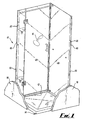
- Fig. 1 illustrates a shower enclosure indicated generally at 10, mounted on a square shower tray 12 against an internal angle (at 14) of walls 16 of a bathroom, shower room etc. The walls are shown broken away, in Fig. 1.
- a conventional shower head illustrated schematically at 18, allows the user to take a shower by standing on the tray 12 within the enclosure 10.
- the enclosure 10 contains the shower water, Which falls to the tray 12 for drainage.
- Fig. 2 shows an arrangement in accordance with the invention, for providing sealing along the edge 22 of one of the sheets 20.
- the assembly 24 includes a channel member 26 having a mouth indicated generally at 28 through which the edge 22 of the sheet 20 is received into the channel of the member 26.
- Gasket strips 30 are provided at the mouth 28.
- the strips 30 are mounted in opposed positions on the channel member 26, by means of T section retaining formations which fit in complementary T section channels at the mouth 28.
- the channel member 26 and the gasket strips 30 may be formed by extrusion, to have a constant cross-section along their entire length, so that the gasket strips 30 can extend along the entire length of the channel member 26.
- the gasket strips 30 are formed of soft, resilient material between which the sheet 20 can be forced to provide slight compression of the strips 30, thereby providing a substantially watertight seal between the sheet 20 and the channel 26. This substantially prevents the ingress of water into the channel, to remove one route for possible leakage.
- a protector member 36 is provided for protecting the glass edge 22.
- the protector 36 (illustrated also in Fig. 3) has a base portion 38 which sits at the base of the channel member 26, and four fingers 42 which project away from the base 38, toward the mouth 28. Two fingers 42 are located to either side of the sheet 20. The fingers 42 extend sufficiently far to ensure that during normal installation, the fingers 42 will embrace the edge 22. Consequently, contact between the edge 22 and the walls of the channel member 26, arising from misalignment of the sheet 20 in the nip between the gaskets 30, is prevented by abutment between the edge 22 and the fingers 42. The significance of this will be described below.
- the base 38 carries leaf springs 44 attached at 46 to the base 38 and flexible therebetween.
- the springs 44 are received in grooves 48 defined between the base 40 and shallow flanges 50 formed in the walls of the channel 26.
- the grooves 48 extend the whole length of the channel 26, by virtue of the extruded nature of the channel 26.
- the springs 44 press into the grooves 48 to provide light restraint on the protector 36, resisting the protector 36 from sliding along the channel 26, once set in position. Further resistance is provided by pegs 51 which sit in corresponding apertures in the channel 26, once set in position.
- an aperture 52 formed through the base 38 for receiving a fixing screw 54 (Fig. 2).
- the base 38 is recessed at 56 around the aperture 52, to receive the screw head 58 without any part of the screw head 58 projecting beyond the base 38, toward the edge 22.
- Corresponding apertures 60 are provided periodically in the base 40, so that the screw 54 serves two fixing purposes, namely to fix the protector 36 in position along the channel 26, and also to mount the channel 26 to the wall 16.
- Apertures 60 are provided at desired spacings along the channel 26, such as a spacing of 20 cm, with a fixing screw 54 being used at each aperture 60. It is preferred that a protector 36 is also used at each aperture 60, in the manner described. Accordingly, a typical installation will include a line of spaced protectors 36, whereas the gasket strips 30 will extend continuously along the length of the channel 26.
- the apertures 60 are visible in Fig. 1, each with two associated apertures for receiving pegs 51.
- the protector 36 may be made of a material such as polypropylene and by moulding, rather than by extrusion. Moulding allows the form of the protector 36 to be much more complex than could be achieved by extrusion (as can be seen from Fig. 3).
- the use of relatively small, moulded components at spaced intervals, as described, also reduces the material requirements for providing the functions of the protector 36, as compared with a continuous component formed by extrusion.
- the protectors 36 would be introduced at one end of the channel 26, engaging the springs 44 into the grooves 48 and sliding the protectors 36 down the channel 26 to the appropriate positions at each aperture 60. It can be seen from Fig. 3 that the pegs 51 have chamfered tips to assist in moving them past positions other than their final position.
- the channel 26 may be provided with the gasket strips 30 already installed, or they may be installed at this stage, by feeding one end into the channels 34 at one end of the channel 26, and feeding the strips 30 along the channels 34 until the strips are in position along the entire length of the channel 26.
- the channel 26 is then offered to the wall 16 at the appropriate position, to run vertically up the wall 16. Fixing screws 54 are then introduced through the mouth 28, through the aperture 52 and the aperture 60, and tightened to mount the channel 26 on the wall 16, simultaneously securing the protector 36 in position along the channel 26.
- the edge 22 of the glass sheet 20 is then introduced between the strips 30, through the mouth 28, into the channel 26, to be located between the fingers 42.
- each protector 36 will be engaged by the edge 22, before the edge 22 is able to engage directly against the material of the channel 26.
- the channel 26 will typically be a metal extrusion which is much harder than the plastics material of the protector 36. Accordingly, the protector 36 will provide a cushion between the edge 22 and the channel 26, protecting the glass sheet 20 against damage. It can readily be understood that shattered glass is highly undesirable during the installation of a shower enclosure, which would normally be used by a bare footed user.
- edge 22 is provided by the base 38.
- the installer pushes the sheet 20 too far into the channel 26, so that the edge 22 approaches the screw heads 58, abutment between the edge 22 and the screw heads 58 will be prevented by the sheet 20 first encountering the material of the base 38, around the recess 56.
- the material of the protector 36 will provide a cushion for the edge 22, in particular preventing direct contact between the edge 22 and the screw head 58.
- the screw head 58 would normally be metal, with consequent risk of damage to the glass in the event of direct contact.
- the edge 22 is significantly spaced from the base 38. It is desirable for the channel 26 to be sufficiently deep for a normal installation to result in relative positions as shown in Figs. 2 and 3. This allows more freedom to accommodate non-standard installations, as follows. If the wall 16 against which the channel 26 is to be installed is not vertical, that is, if the intersection of the plane of the sheet 20 and the plane of the wall 16 is not vertical, the channel 26 will not be vertical when attached to the wall 16 and viewed perpendicular to the plane of the sheet 20. This can be accommodated by having the edge 22 more deeply in the channel 26 at one end than at the other. The edge 22 remains protected, as described, both against misalignment (by abutment with the fingers 42) and against excessive penetration (by the base 38), as has been described.
- the position of the sheet 20 relative to the channel 26 may be maintained by the grip exerted on the edge 22 by the gasket strips 30. However, this may introduce a further risk of damage to the glass 20. It is thus preferred that the relative positions are maintained by additional brace arrangements 62 (Fig. 4).
- a brace 62 is attached to the sheet 20 and to the wall 16, thereby holding the sheet 20 relative to the wall 16.
- the brace 62 may be adjustable in various ways, to allow the final position of the sheet 20 to be set.
- the brace 60 may include an arm 64 of adjustable length, carrying heads 66 for attachment to the glass 20 and the wall 16, by means of pivots at 68, allowing the angle of the arm 64 to be varied.
- the brace 62 may be adapted for other functional purposes, such as carrying a soap dish 70.
- the brace 62 will be visible to a user of the shower, and is thus preferably finished in an aesthetic manner.
- the channel member 26 will be extruded from metal and that the gasket strips 30 will be extruded from a resilient plastics material.
- the protector 36 is preferably moulded, as has been described, and may have a resilience which is between that of the relatively soft seal of the strips 30, and the rigidity of the channel member 26.
- the dimensions of the protector 36 can be chosen in conjunction with the choice of material, to provide adequate cushioning of the edge 22, to protect it during expected normal usage.
Landscapes
- Health & Medical Sciences (AREA)
- Public Health (AREA)
- Epidemiology (AREA)
- General Health & Medical Sciences (AREA)
- Bathtubs, Showers, And Their Attachments (AREA)
Applications Claiming Priority (2)
| Application Number | Priority Date | Filing Date | Title |
|---|---|---|---|
| GB0330066 | 2003-12-27 | ||
| GB0330066A GB0330066D0 (en) | 2003-12-27 | 2003-12-27 | Sheet edge support |
Publications (1)
| Publication Number | Publication Date |
|---|---|
| EP1547503A1 true EP1547503A1 (de) | 2005-06-29 |
Family
ID=31503209
Family Applications (1)
| Application Number | Title | Priority Date | Filing Date |
|---|---|---|---|
| EP04257709A Withdrawn EP1547503A1 (de) | 2003-12-27 | 2004-12-11 | Scheibenrandstütze |
Country Status (2)
| Country | Link |
|---|---|
| EP (1) | EP1547503A1 (de) |
| GB (1) | GB0330066D0 (de) |
Cited By (6)
| Publication number | Priority date | Publication date | Assignee | Title |
|---|---|---|---|---|
| WO2007017620A1 (en) * | 2005-08-09 | 2007-02-15 | Dlp Limited | Compensator device |
| GB2453133A (en) * | 2007-09-26 | 2009-04-01 | Majestic Shower Company Ltd | Shower screen |
| CN101766457A (zh) * | 2010-01-25 | 2010-07-07 | 张烜铭 | 一种屏风式连体折叠复合纤维薄膜洗浴房 |
| DE102014007697A1 (de) * | 2014-05-22 | 2015-12-17 | Roto Frank Ag | Abstützelement zur Montagehilfe bei einem Flügelrahmen eines Wohndachfensters sowie Verfahren zum Einhängen und/oder Aushängen eines Flügelrahmens |
| CN108601488A (zh) * | 2015-12-16 | 2018-09-28 | 阿罗玻璃镜业有限公司 | 淋浴围封间头 |
| WO2020249761A1 (en) * | 2019-06-14 | 2020-12-17 | Merlyn Industries Limited | An adjustable coupling apparatus and a method for coupling a screen or a panel to a structure |
Citations (3)
| Publication number | Priority date | Publication date | Assignee | Title |
|---|---|---|---|---|
| DE2159520A1 (de) * | 1970-12-07 | 1972-06-15 | Schiekmetall, Paul Schiek & Co KG, Wien | Verglasung |
| US4134238A (en) * | 1976-06-24 | 1979-01-16 | Saint-Gobain Industries | Assembly of shaped leaves |
| GB2294965A (en) * | 1994-11-02 | 1996-05-15 | Komfort Systems Ltd | Glass panel edge gasket and framing members for a partitioning system |
-
2003
- 2003-12-27 GB GB0330066A patent/GB0330066D0/en not_active Ceased
-
2004
- 2004-12-11 EP EP04257709A patent/EP1547503A1/de not_active Withdrawn
Patent Citations (3)
| Publication number | Priority date | Publication date | Assignee | Title |
|---|---|---|---|---|
| DE2159520A1 (de) * | 1970-12-07 | 1972-06-15 | Schiekmetall, Paul Schiek & Co KG, Wien | Verglasung |
| US4134238A (en) * | 1976-06-24 | 1979-01-16 | Saint-Gobain Industries | Assembly of shaped leaves |
| GB2294965A (en) * | 1994-11-02 | 1996-05-15 | Komfort Systems Ltd | Glass panel edge gasket and framing members for a partitioning system |
Cited By (8)
| Publication number | Priority date | Publication date | Assignee | Title |
|---|---|---|---|---|
| WO2007017620A1 (en) * | 2005-08-09 | 2007-02-15 | Dlp Limited | Compensator device |
| GB2453133A (en) * | 2007-09-26 | 2009-04-01 | Majestic Shower Company Ltd | Shower screen |
| CN101766457A (zh) * | 2010-01-25 | 2010-07-07 | 张烜铭 | 一种屏风式连体折叠复合纤维薄膜洗浴房 |
| CN101766457B (zh) * | 2010-01-25 | 2015-01-07 | 张烜铭 | 一种屏风式连体折叠复合纤维薄膜洗浴房 |
| DE102014007697A1 (de) * | 2014-05-22 | 2015-12-17 | Roto Frank Ag | Abstützelement zur Montagehilfe bei einem Flügelrahmen eines Wohndachfensters sowie Verfahren zum Einhängen und/oder Aushängen eines Flügelrahmens |
| CN108601488A (zh) * | 2015-12-16 | 2018-09-28 | 阿罗玻璃镜业有限公司 | 淋浴围封间头 |
| CN108601488B (zh) * | 2015-12-16 | 2021-05-07 | 阿罗玻璃镜业有限公司 | 淋浴围封间头 |
| WO2020249761A1 (en) * | 2019-06-14 | 2020-12-17 | Merlyn Industries Limited | An adjustable coupling apparatus and a method for coupling a screen or a panel to a structure |
Also Published As
| Publication number | Publication date |
|---|---|
| GB0330066D0 (en) | 2004-02-04 |
Similar Documents
| Publication | Publication Date | Title |
|---|---|---|
| US9010033B2 (en) | Wall rail system | |
| EP0740519B1 (de) | Verstellbare zarge | |
| RU2733242C2 (ru) | Система хранения, покрывающая накладка и способ изготолвления покрывающей накладки | |
| US8110743B2 (en) | Electrical box cover with insect guard | |
| CA2481856C (en) | Combination mounting bracket and adapter plate for mounting electrical boxes | |
| US20160262277A1 (en) | Rail seal for electronic equipment enclosure | |
| GB2571437A (en) | Wall mount for an electronic display, computer arrangement and method for mounting an electronic display and a computer system to a wall | |
| RU2681088C2 (ru) | Электрическое устройство с защищенным соединением | |
| CN101399434A (zh) | 密封组件 | |
| RU2004100941A (ru) | Перемещаемое по высоте средство защиты угловых кромок | |
| US20060117684A1 (en) | Modular raceway | |
| EP1547503A1 (de) | Scheibenrandstütze | |
| US20110173906A1 (en) | Floor gland | |
| CA2603884A1 (en) | Support frame and cover plate for wall mounting an electrical apparatus | |
| JP2019216637A (ja) | 防鳥装置 | |
| US10790611B1 (en) | Telecommunication box connector with protective outer shield | |
| HU223720B1 (hu) | Szerelvénytartó kábelcsatornához | |
| GB2330855A (en) | A protective strip for a door edge | |
| US20140332638A1 (en) | Backplate for a utility box | |
| US6343947B1 (en) | Mounting assembly with dual entry cantilever latch | |
| KR102365985B1 (ko) | 케이블 몰드 | |
| CN204869866U (zh) | 玻璃背板 | |
| US6274818B1 (en) | Universal cable designation/retainer assembly | |
| KR100763283B1 (ko) | 벽걸이 디스플레이 장치용 월 마운트 장치 | |
| CN220359378U (zh) | 一种防护网结构及电加热装置 |
Legal Events
| Date | Code | Title | Description |
|---|---|---|---|
| PUAI | Public reference made under article 153(3) epc to a published international application that has entered the european phase |
Free format text: ORIGINAL CODE: 0009012 |
|
| AK | Designated contracting states |
Kind code of ref document: A1 Designated state(s): AT BE BG CH CY CZ DE DK EE ES FI FR GB GR HU IE IS IT LI LT LU MC NL PL PT RO SE SI SK TR |
|
| AX | Request for extension of the european patent |
Extension state: AL BA HR LV MK YU |
|
| 17P | Request for examination filed |
Effective date: 20050628 |
|
| AKX | Designation fees paid |
Designated state(s): AT BE BG CH CY CZ DE DK EE ES FI FR GB GR HU IE IS IT LI LT LU MC NL PL PT RO SE SI SK TR |
|
| 17Q | First examination report despatched |
Effective date: 20081125 |
|
| STAA | Information on the status of an ep patent application or granted ep patent |
Free format text: STATUS: THE APPLICATION IS DEEMED TO BE WITHDRAWN |
|
| 18D | Application deemed to be withdrawn |
Effective date: 20090606 |