EP1547224B1 - Überwachungssystem und einrichtung für ein elektrisches stromversorgungsleitungsnetzwerk - Google Patents
Überwachungssystem und einrichtung für ein elektrisches stromversorgungsleitungsnetzwerk Download PDFInfo
- Publication number
- EP1547224B1 EP1547224B1 EP03799737A EP03799737A EP1547224B1 EP 1547224 B1 EP1547224 B1 EP 1547224B1 EP 03799737 A EP03799737 A EP 03799737A EP 03799737 A EP03799737 A EP 03799737A EP 1547224 B1 EP1547224 B1 EP 1547224B1
- Authority
- EP
- European Patent Office
- Prior art keywords
- line
- multisensor
- camera
- power
- temperature
- Prior art date
- Legal status (The legal status is an assumption and is not a legal conclusion. Google has not performed a legal analysis and makes no representation as to the accuracy of the status listed.)
- Expired - Lifetime
Links
Images




Classifications
-
- H—ELECTRICITY
- H02—GENERATION; CONVERSION OR DISTRIBUTION OF ELECTRIC POWER
- H02J—ELECTRIC POWER NETWORKS; CIRCUIT ARRANGEMENTS OR SYSTEMS FOR SUPPLYING OR DISTRIBUTING ELECTRIC POWER; SYSTEMS FOR STORING ELECTRIC ENERGY
- H02J13/00—Circuit arrangements for providing remote monitoring or remote control of equipment in a power distribution network
- H02J13/12—Monitoring network conditions, e.g. electrical magnitudes or operational status
-
- H—ELECTRICITY
- H02—GENERATION; CONVERSION OR DISTRIBUTION OF ELECTRIC POWER
- H02J—ELECTRIC POWER NETWORKS; CIRCUIT ARRANGEMENTS OR SYSTEMS FOR SUPPLYING OR DISTRIBUTING ELECTRIC POWER; SYSTEMS FOR STORING ELECTRIC ENERGY
- H02J13/00—Circuit arrangements for providing remote monitoring or remote control of equipment in a power distribution network
- H02J13/13—Circuit arrangements for providing remote monitoring or remote control of equipment in a power distribution network characterised by the transmission of data to equipment in the power network
- H02J13/1331—Circuit arrangements for providing remote monitoring or remote control of equipment in a power distribution network characterised by the transmission of data to equipment in the power network using wireless data transmission
-
- H—ELECTRICITY
- H02—GENERATION; CONVERSION OR DISTRIBUTION OF ELECTRIC POWER
- H02J—ELECTRIC POWER NETWORKS; CIRCUIT ARRANGEMENTS OR SYSTEMS FOR SUPPLYING OR DISTRIBUTING ELECTRIC POWER; SYSTEMS FOR STORING ELECTRIC ENERGY
- H02J13/00—Circuit arrangements for providing remote monitoring or remote control of equipment in a power distribution network
- H02J13/18—Circuit arrangements for providing remote monitoring or remote control of equipment in a power distribution network characterised by the remotely-controlled equipment, e.g. converters or transformers
- H02J13/333—Circuit arrangements for providing remote monitoring or remote control of equipment in a power distribution network characterised by the remotely-controlled equipment, e.g. converters or transformers the equipment forming part of substations
-
- Y—GENERAL TAGGING OF NEW TECHNOLOGICAL DEVELOPMENTS; GENERAL TAGGING OF CROSS-SECTIONAL TECHNOLOGIES SPANNING OVER SEVERAL SECTIONS OF THE IPC; TECHNICAL SUBJECTS COVERED BY FORMER USPC CROSS-REFERENCE ART COLLECTIONS [XRACs] AND DIGESTS
- Y02—TECHNOLOGIES OR APPLICATIONS FOR MITIGATION OR ADAPTATION AGAINST CLIMATE CHANGE
- Y02B—CLIMATE CHANGE MITIGATION TECHNOLOGIES RELATED TO BUILDINGS, e.g. HOUSING, HOUSE APPLIANCES OR RELATED END-USER APPLICATIONS
- Y02B70/00—Technologies for an efficient end-user side electric power management and consumption
- Y02B70/30—Systems integrating technologies related to power network operation and communication or information technologies for improving the carbon footprint of the management of residential or tertiary loads, i.e. smart grids as climate change mitigation technology in the buildings sector, including also the last stages of power distribution and the control, monitoring or operating management systems at local level
-
- Y—GENERAL TAGGING OF NEW TECHNOLOGICAL DEVELOPMENTS; GENERAL TAGGING OF CROSS-SECTIONAL TECHNOLOGIES SPANNING OVER SEVERAL SECTIONS OF THE IPC; TECHNICAL SUBJECTS COVERED BY FORMER USPC CROSS-REFERENCE ART COLLECTIONS [XRACs] AND DIGESTS
- Y02—TECHNOLOGIES OR APPLICATIONS FOR MITIGATION OR ADAPTATION AGAINST CLIMATE CHANGE
- Y02E—REDUCTION OF GREENHOUSE GAS [GHG] EMISSIONS, RELATED TO ENERGY GENERATION, TRANSMISSION OR DISTRIBUTION
- Y02E60/00—Enabling technologies; Technologies with a potential or indirect contribution to GHG emissions mitigation
-
- Y—GENERAL TAGGING OF NEW TECHNOLOGICAL DEVELOPMENTS; GENERAL TAGGING OF CROSS-SECTIONAL TECHNOLOGIES SPANNING OVER SEVERAL SECTIONS OF THE IPC; TECHNICAL SUBJECTS COVERED BY FORMER USPC CROSS-REFERENCE ART COLLECTIONS [XRACs] AND DIGESTS
- Y04—INFORMATION OR COMMUNICATION TECHNOLOGIES HAVING AN IMPACT ON OTHER TECHNOLOGY AREAS
- Y04S—SYSTEMS INTEGRATING TECHNOLOGIES RELATED TO POWER NETWORK OPERATION, COMMUNICATION OR INFORMATION TECHNOLOGIES FOR IMPROVING THE ELECTRICAL POWER GENERATION, TRANSMISSION, DISTRIBUTION, MANAGEMENT OR USAGE, i.e. SMART GRIDS
- Y04S10/00—Systems supporting electrical power generation, transmission or distribution
- Y04S10/30—State monitoring, e.g. fault, temperature monitoring, insulator monitoring, corona discharge
-
- Y—GENERAL TAGGING OF NEW TECHNOLOGICAL DEVELOPMENTS; GENERAL TAGGING OF CROSS-SECTIONAL TECHNOLOGIES SPANNING OVER SEVERAL SECTIONS OF THE IPC; TECHNICAL SUBJECTS COVERED BY FORMER USPC CROSS-REFERENCE ART COLLECTIONS [XRACs] AND DIGESTS
- Y04—INFORMATION OR COMMUNICATION TECHNOLOGIES HAVING AN IMPACT ON OTHER TECHNOLOGY AREAS
- Y04S—SYSTEMS INTEGRATING TECHNOLOGIES RELATED TO POWER NETWORK OPERATION, COMMUNICATION OR INFORMATION TECHNOLOGIES FOR IMPROVING THE ELECTRICAL POWER GENERATION, TRANSMISSION, DISTRIBUTION, MANAGEMENT OR USAGE, i.e. SMART GRIDS
- Y04S20/00—Management or operation of end-user stationary applications or the last stages of power distribution; Controlling, monitoring or operating thereof
- Y04S20/20—End-user application control systems
- Y04S20/242—Home appliances
-
- Y—GENERAL TAGGING OF NEW TECHNOLOGICAL DEVELOPMENTS; GENERAL TAGGING OF CROSS-SECTIONAL TECHNOLOGIES SPANNING OVER SEVERAL SECTIONS OF THE IPC; TECHNICAL SUBJECTS COVERED BY FORMER USPC CROSS-REFERENCE ART COLLECTIONS [XRACs] AND DIGESTS
- Y04—INFORMATION OR COMMUNICATION TECHNOLOGIES HAVING AN IMPACT ON OTHER TECHNOLOGY AREAS
- Y04S—SYSTEMS INTEGRATING TECHNOLOGIES RELATED TO POWER NETWORK OPERATION, COMMUNICATION OR INFORMATION TECHNOLOGIES FOR IMPROVING THE ELECTRICAL POWER GENERATION, TRANSMISSION, DISTRIBUTION, MANAGEMENT OR USAGE, i.e. SMART GRIDS
- Y04S40/00—Systems for electrical power generation, transmission, distribution or end-user application management characterised by the use of communication or information technologies, or communication or information technology specific aspects supporting them
- Y04S40/12—Systems for electrical power generation, transmission, distribution or end-user application management characterised by the use of communication or information technologies, or communication or information technology specific aspects supporting them characterised by data transport means between the monitoring, controlling or managing units and monitored, controlled or operated electrical equipment
- Y04S40/126—Systems for electrical power generation, transmission, distribution or end-user application management characterised by the use of communication or information technologies, or communication or information technology specific aspects supporting them characterised by data transport means between the monitoring, controlling or managing units and monitored, controlled or operated electrical equipment using wireless data transmission
Definitions
- the present invention relates to a device for monitoring an electric overhead transmission line.
- Power lines for transmission of electric power are dimensioned for the amperage to be transmitted, and for the length of the line spans in question. In addition, due consideration must be taken with regard to exposing the line span to wind, as well as the weighing down by snow and ice in northern areas.
- the power lines may become strongly heated by the sun and by a generally high air temperature, and if currents are then transmitted with amperages approaching the maximum amperage for which the line is designed, the wire may experience such a large sag increase that it will be perilous to enter the area thereunder. Also in other areas the increase of sag for the power lines in summer, may cause that the distance to trees thereunder will be too short. This may cause a flashover from the power line to the trees, and may result in forest fires and electrical power failure.
- the power network companies may experience the problem that it is difficult to transmit the energy amount that the power line was actually constructed for.
- a power supplier may be under the delusion that the energy transmission takes place in accordance with statutory safety routines and with the necessary safety margins, but has in reality no control over ambient temperature, solar heating etc. that in reality will determine the transmission capacity of the line.
- the present invention aims at solving the above mentioned problems.
- the solution in accordance with the invention is a device for monitoring an electric overhead line, and the device is defined precisely in the appended claim 1.
- Favourable and preferable embodiments appear from the attached claims 2-11.
- the present invention provides the possibility of real time regulating of maximum transferable power, since it will be possible to monitor continuously from a power plant the condition of the power lines in question, so that overload, forest fire and dangerous passage of persons can be avoided, while at the same time capacity of the lines can be utilized at a maximum.
- one of the aspects of the invention consists in a device that can be designated as a "multisensor" that is able to detect, and output signals regarding, a plurality of parameters that are of importance for power lines.
- a multisensor that is able to detect, and output signals regarding, a plurality of parameters that are of importance for power lines.
- it is not necessarily important to monitor all parameters, but some of the parameters mentioned here, will always be of interest: it concerns line temperature, which is measured by a probe that engages the line itself, air temperature to be measured by a probe directed outward into the air, line slope or line sag increase, galloping, wind speed, wind direction, concentration of precipitation particles in the air, distance to ground level, quality of line current, snow/ice load on the line, and a visual image of the line.
- Increase of line sag is measured by detecting a slope angle, for instance by means of mercury switches.
- Sag increase can be due to various factors, such as previously mentioned. If the sag increase measurement is set in connection with a temperature measurement, snow and ice load can be determined.
- the quality and stability of current flowing in the line can be measured by means of a measurement transformer, while wind speed and wind direction are measured by means of a traditional wind gauge.
- the distance to ground level is measured separately by means of a built-in laser range finder.
- the concentration of raindrops or snow particles in the air can be measured by a laser particle counter that comprises a mirror for a light fan from a laser. Rain and snow have a cooling effect on a line, and such a cooling influence is a factor that must be included in a prognosis.
- the multisensor includes "visual safety backup" by having mounted therein a camera that can be used to see visually the various warning signals.
- the camera has an independent function for monitoring the line itself, weather conditions around the line and vegetation below the line.
- Warning regarding "galloping line” has been mentioned above, and this means a warning regarding a damaging phenomenon for a line, namely a vibration mode in which a waveform propagates along the line, usually started by wind.
- a propagating wave, or for that matter a standing wave, along the line may have amplitudes large enough to result in damage. It is therefore important to detect such a motion, i.e. receiving an automatic warning regarding such a motion from a sensor device in accordance with the invention, because then the current can be shut down before destruction occurs, and the damage can then be limited.
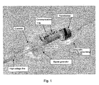
- the device is attached tightly to the high voltage line and surrounding the line.
- a camera is arranged so as to peer out through a window with a field of view along the line and preferably below the line.
- a transformer is arranged to collect operating power from the very current through the line, and in connection with this power transformer there is also a measurement transformer for checking the stability and quality of the line current.
- sensors/signal generators are arranged for sag measurement, in the form of mercury switches.
- circuitry for generating signals regarding temperature in the line and the surrounding air, respectively, and these signals are generated on the basis of measurement signals from temperature probes engaging the line itself, and outside the outer casing.
- the multisensor device also contains a log for recording measurements, as well as a communication unit, which unit is, in the preferred embodiment, able to perform two-way communication.
- a communication unit which unit is, in the preferred embodiment, able to perform two-way communication. This means that the unit, in addition to transmitting radio frequency signals to a remote central, is also capable of receiving control signals from the same central.
- the preferred embodiment also comprises a wind gauge, which is not visible in the drawing.
- the wind gauge operates of course in connection with an opening in the outer casing.
- a laser range finder is incorporated in the signal generator box, and measures the distance to the terrain below, through a window in the outer casing.
- the outer casing comprises, in the preferred embodiment of the device, space for outside information or advertisement.
- FIG. 2 appears an alternative embodiment of the device in accordance with the invention.
- a central section that contains a current transformer for fetching operating power from the magnetic field of the power line, is divided in two so as to make the installation on the power line simple and rapid.
- the two box-like units on the sides contain single sensors of the above mentioned types, there is for instance an opening shown in the front left side for an internal camera, and in addition there is communication equipment and a possible logging means.
- FIG. 3 appears an image recorded by a camera built into a device in accordance with the invention, which image shows the situation around the line such as it would appear visually, and in addition a bar has been laid in at the top of the picture, to show the temperatures of the air and of the line.
- Such an image can be transmitted as a radio signal.
- the device in accordance with the invention constitutes a multisensor, which means that the device is able to measure a number of different parameters, but the device can also be specially adapted to deal with fewer parameters, or possibly more parameters, depending on the conditions in the actual location.
- What is regarded as minimum equipment in the sensor are a slope gauge and temperature probes for air and line temperatures, laser range finder and camera.
- the slope gauge preferably in the form of a mercury switch or relay with a ball (ball relay)
- the temperature probes provide information regarding the reason for the possible sag increase, namely either overheating of the line, or ice/snow load at low temperatures.
- the temperature probes are preferably bimetallic temperature probes. Correct distance to structures below the line, is measured directly by a laser range finder, and the measurement is double-checked by the camera surveillance.
- Transmission equipment is obligatory, but receiver equipment for receiving control signals, should preferably be included also.
- a simple and effective design of the multisensor can work in the following exemplary manner: bimetallic temperature probes are connected in series with slope angle gauges, for instance in the form of mercury switches.
- the mercury switches operate by forming contact, or breaking contact, depending on the inclination of the switch.
- the mercury switches are mounted in the multisensor with adjustment screws so that a default angle can be adjusted, and then in such a manner that contact is formed or broken for a certain angle of inclination.
- this type of slope gauge it is detected only whether the angle of inclination is above or below a certain limit angle.
- several such gauges can be mounted if it is desirable to have detection ranges of finer graduation.
- the multisensor in accordance with the invention shall always measure the slope of the line, the sensor must be mounted at a proper distance from the mid-point of a span, because at mid-point the slope will normally be equal to 0, no matter how much the sag is increased.
- the sensor can advantageously be mounted in an area midway between a pylon and the mid-point of the span, or possibly even closer to the pylon.
- mercury switches/slope gauges for detecting change in sag, were mentioned above.
- the preferable number could be two such gauges, namely one regarding "50%" of a critical value, and one further mercury switch for the critical value itself.
- a signal regarding a galloping line is obtained on the basis of the same technical solution, using for example a mercury switch as a slope gauge, but then a mercury switch which is turned 180° relative to the above mentioned mercury switches.
- the galloping detector responds to an inverse slope of the line, which is typical for the galloping phenomenon. Since this phenomenon is of a rapid and transient type, measures are preferably made to avoid that a galloping signal arises and disappears in step with the galloping. Therefore, a relay is mounted and set for a desired, timed hold contact, or the signal must be signed out. Hence, greater security is obtained regarding detecting an incoming galloping signal in the central.
- galloping may occur in two perpendicular planes, namely mostly in the plane spanned by the line span itself, which is a vertical plane, but the oscillations may also occur in a horizontal plane.
- galloping in both planes can be detected by means of one and the same mercury switch.
- the laser range finder checks continuously the distance from the line to the ground level, and consequently the remaining signals regarding line deviations, i.e. increased sag and possible galloping, can be verified.
- the multisensor does not twist around the line.
- the sensor should therefore be attached firmly from the start, but in addition, if the line itself is exposed to twisting movements about its axis, the sensor could be equipped with a cylindrically rotatable suspension to ensure that the multisensor stays at rest relative to a vertical plane, i.e. that it does not rotate relative to the surroundings.
- the sensor device preferably has transmitter modules for every signal to be transmitted. Preferably, it also contains a receiver system, so that it will be possible to activate the camera for visual inspection, or to activate other single sensors in order to double-check signals that have been received in the central. All signals are transmitted via the power company's own data system, which system is based on for instance the RTU system, possibly the Scada system, or using RF signals. All signals are logged. The central receives the signals and can make decisions regarding transmission of more or less power through the lines where the sensor devices are mounted. Because the sensor devices transmit signals to the central, where the signals are logged, it is possible to implement measures prior to a possible breakdown.
- control room receives a signal to the effect that a line span is galloping, this provides an opportunity to load power over to another power line before the first one breaks down, and in such a manner it will be possible to avoid power shut-off for some areas.
- the logging of the signals will provide a possibility for preparing trends and statistics for the various power lines where the system is mounted, so that it will be possible to have documented statistics based on real time measurements.
- the pricing of the power company may appear there, or possibly the power amount that is transmitted through the line.
- Such an information device could of course be developed further to be able to display variable information, particularly in a context as previously mentioned, where operating power can be taken from the line itself. In such a case, operating a variable display is no problem. This may be of special interest for instance where power lines cross communication arteries like for instance roads or canals.
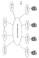
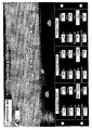
- Fig 7 shows a possible monitoring picture on a computer display unit in an operation central.
- the monitored power line is identified. It is realized that this power line extends from location R ⁇ yk ⁇ s to location F ⁇ berg, and it is a 300 kV line.
- Multisensor devices in accordance with the invention have been arranged in three special positions, namely position "Sinnataggen" with identification ID02, position “Ambolten” (ID03) and position “Gluggen” (ID04), and it is noted that the three locations would normally have been selected with a spacing of about 10 km. (In the drawing, it looks as if the three locations are in adjacent line spans, but this is merely a chosen visual design for the display picture.)
- the respective multisensor devices In the lower part of the display picture, the respective multisensor devices have their own areas with indications regarding important parameters.
- position "Gluggen” at the far right in the picture it is realized that position “Gluggen” would necessarily be relatively far away from “Sinnataggen” at the far left.
- the conditions at position “Gluggen” are winter conditions, the air temperature being -18°C, a snow/ice load of 72 kg is detected, and this results in a sag increase that is critical, with a distance to ground of only 11,1 m.
- buttons that can be clicked, one for a snow/ice vibrator, which in this case is "off", and to the right a switch for camera lights, which in this case is "on".
- a clickable button (“main") is arranged in the display picture to provide a possibility to return to the main picture (i.e. the picture of fig. 7).
- one of the main tasks for the multisensor devices is to measure in real time the topical parameters that influence the ability of the power lines to maintain the function, that is conductor temperature, air temperature, sag, camera image with a general view and more, as mentioned above. These parameters are then transmitted as radio signals to an operation central, and are then deciding parameters regarding the transmission capacity of the line.
- the measurements from the multisensor device will also form a basis for the "rating" hour by hour for the line, i.e. it is desirable to determine with the real time measurements the transmission capacity of the power line with 100% certainty, hour by hour. (The reason for the time aspect "hour by hour" is the thermal inertia of the line.)
- the multisensor device will provide immediately an alarm for an operation central.
Landscapes
- Engineering & Computer Science (AREA)
- Power Engineering (AREA)
- Remote Monitoring And Control Of Power-Distribution Networks (AREA)
- Electric Cable Installation (AREA)
- Cable Transmission Systems, Equalization Of Radio And Reduction Of Echo (AREA)
- Arrangements For Transmission Of Measured Signals (AREA)
- Length Measuring Devices By Optical Means (AREA)
Claims (11)
- Vorrichtung zum Überwachen einer elektrischen Freileitung, die Vorrichtung ist ein unabhängig arbeitender Echtzeit-Multisensor zum Befestigen in einer Position in einem Leitungsbereich und weist einen eingebauten Sender zum Senden von Sensorsignalen aus eingebauten Sensoren zum Erfassen wenigstens eines Parameters in einer Parametergruppe, die Neigungswinkel, Zunahme des Leitungsdurchhangs, Windgeschwindigkeit, Windrichtung, Qualität/Stabilität des Leitungsstroms, Leitungstemperatur und Lufttemperatur umfasst, zu einer entfernt gelegenen Zentrale auf und ist dadurch gekennzeichnet, dass der Multisensor des Weiteren eine Kamera zur Echtzeit-Bildüberwachung der Leitung und ihrer Umgebung umfasst, wobei die Kamera des Weiteren betriebsfähig ist, um wenigstens einen der Parameter visuell als einen Teil des Kamerabildes darzustellen und das Kamerabild als ein Sensorsignal in Echtzeit zu der Zentrale gesendet wird.
- Vorrichtung nach Anspruch 1, dadurch gekennzeichnet, dass der Multisensor des Weiteren einen Laser-Entfernungsmesser zum direkten Messen des Abstandes genau darunter liegenden Bodens umfasst, wobei der Abstand in die Parametergruppe eingefügt wird und in dem gesendeten Kamerabild darstellbar ist.
- Vorrichtung nach Anspruch 1, dadurch gekennzeichnet, dass der Multisensor des Weiteren einen Bimetall-Temperaturfühler, einen Quecksilber-Neigungsschalter, Kugelschalter, eine Kamera, einen Windmesser, einen Laser-Entfernungsmesser und einen Messwandler zum Erfassen der Parameter und zum optionalen Anzeigen in dem gesendeten Kamerabild umfasst.
- Vorrichtung nach Anspruch 1, dadurch gekennzeichnet, dass der Multisensor mit Schaltungstechnik ausgestattet ist, um eine Trigger-Funktion für das Senden eines Warnsignals bereitzustellen, wenn voreingestellte Schwellenwerte der Temperatur oder anderer der Parameter überschritten werden.
- Vorrichtung nach Anspruch 1, dadurch gekennzeichnet, dass der Multisensor einen Stromtransformator zum Gewinnen der Betriebsleistung aus der Freileitung selbst umfasst.
- Vorrichtung nach Anspruch 1, dadurch gekennzeichnet, dass der Multisensor ein Solarzellensystem und eine Batterie für die Bereitstellung der Betriebsleistung umfasst.
- Vorrichtung nach Anspruch 1, dadurch gekennzeichnet, dass der Multisensor oder ein Teil davon als zwei klappbare Halbzylinder zum Befestigen der Halbzylinder durch Zusammenklappen um die Leitung ausgebildet ist.
- Vorrichtung nach Anspruch 1, dadurch gekennzeichnet, dass die äußere Oberfläche davon mit sichtbaren Informationen/sichtbarer Werbung versehen ist.
- Vorrichtung nach Anspruch 1, dadurch gekennzeichnet, dass der Multisensor einen Empfänger für Steuersignale von der Zentrale umfasst.
- Vorrichtung nach Anspruch 1, gekennzeichnet dadurch, dass der Sender ein Funksender ist.
- Vorrichtung nach Anspruch 1, dadurch gekennzeichnet, dass der Sender an die Stromleitung selbst angeschlossen ist, um die Stromleitung als Übertragungsmedium zur Zentrale zu nutzen.
Applications Claiming Priority (3)
| Application Number | Priority Date | Filing Date | Title |
|---|---|---|---|
| NO20024833A NO318809B1 (no) | 2002-10-07 | 2002-10-07 | Anordning for overvakning av en elektrisk luftstrekk-ledning |
| NO20024833 | 2002-10-07 | ||
| PCT/NO2003/000334 WO2004038891A2 (en) | 2002-10-07 | 2003-10-07 | System and device for monitoring an overhead power line |
Publications (2)
| Publication Number | Publication Date |
|---|---|
| EP1547224A2 EP1547224A2 (de) | 2005-06-29 |
| EP1547224B1 true EP1547224B1 (de) | 2006-12-20 |
Family
ID=19914074
Family Applications (1)
| Application Number | Title | Priority Date | Filing Date |
|---|---|---|---|
| EP03799737A Expired - Lifetime EP1547224B1 (de) | 2002-10-07 | 2003-10-07 | Überwachungssystem und einrichtung für ein elektrisches stromversorgungsleitungsnetzwerk |
Country Status (10)
| Country | Link |
|---|---|
| US (1) | US7369045B2 (de) |
| EP (1) | EP1547224B1 (de) |
| AT (1) | ATE349092T1 (de) |
| AU (1) | AU2003299443A1 (de) |
| DE (1) | DE60310587T2 (de) |
| DK (1) | DK1547224T3 (de) |
| ES (1) | ES2279223T3 (de) |
| NO (1) | NO318809B1 (de) |
| PT (1) | PT1547224E (de) |
| WO (1) | WO2004038891A2 (de) |
Cited By (2)
| Publication number | Priority date | Publication date | Assignee | Title |
|---|---|---|---|---|
| CN102155935A (zh) * | 2011-03-08 | 2011-08-17 | 四川电力科学研究院 | 一种输电线路分裂导线覆冰翻转角度检测装置的检测方法 |
| CN106092187B (zh) * | 2015-12-17 | 2018-01-30 | 刘秀兰 | 高压线路环境参数采集报警平台 |
Families Citing this family (215)
| Publication number | Priority date | Publication date | Assignee | Title |
|---|---|---|---|---|
| WO2007031435A1 (en) | 2005-09-16 | 2007-03-22 | Universite De Liege | Device, system and method for real-time monitoring of overhead power lines |
| US20070112481A1 (en) * | 2005-11-11 | 2007-05-17 | Dong-Huang Tsai | Wireless rail detection system |
| PL2021753T3 (pl) * | 2006-05-11 | 2016-12-30 | Układ monitorowania temperatury oraz zwisu linii elektroenergetycznej | |
| US7786894B2 (en) | 2006-06-20 | 2010-08-31 | Battelle Energy Alliance, Llc | Methods, apparatus, and systems for monitoring transmission systems |
| US7641387B2 (en) * | 2007-05-08 | 2010-01-05 | Underground Systems, Inc. | Power line temperature and sag monitor system |
| KR100936543B1 (ko) * | 2007-11-16 | 2010-01-13 | 현대중공업 주식회사 | 송전선로용 모니터링 센서 및 이를 갖는 송전선로용 원격모니터링 설비 |
| KR100999578B1 (ko) * | 2008-08-14 | 2010-12-08 | 한전케이디엔주식회사 | 반구 결합형 송전선로 취부형 구형 센서함 |
| US20100102992A1 (en) * | 2008-10-28 | 2010-04-29 | Honeywell International Inc. | Systems and methods for remote monitoring of weather |
| MX2011004874A (es) | 2008-11-06 | 2011-11-01 | Southwire Co | Grado de linea de energia en tiempo real. |
| US8002592B2 (en) | 2008-12-17 | 2011-08-23 | Hubbell Incorporated | Data collecting connection |
| FR2943792B1 (fr) * | 2009-03-30 | 2011-05-06 | Areva T & D Sa | Capteur de courant en forme d'un cable a attacher en boucle |
| CN102625916A (zh) * | 2009-07-18 | 2012-08-01 | 纳克斯伦特有限责任公司 | 电力系统传感器装置、电力系统监测方法以及电力系统监测系统 |
| US20120176103A1 (en) * | 2009-09-03 | 2012-07-12 | Verivolt, Llc | Voltage Conversion and/or Electrical Measurements from 400 Volts Upwards |
| KR101083000B1 (ko) | 2009-10-21 | 2011-11-11 | 한전케이디엔주식회사 | 송전선로 환경감시 시스템 및 제어방법 |
| CN102792239B (zh) * | 2010-02-09 | 2014-10-15 | 尼尔森灌溉公司 | 分布式控制系统及控制灌溉系统中的多个灌溉器的方法 |
| US10205307B2 (en) | 2010-03-23 | 2019-02-12 | Southwire Company, Llc | Power line maintenance monitoring |
| JP2011228884A (ja) * | 2010-04-19 | 2011-11-10 | Sony Corp | 撮像装置及び撮像装置の制御方法 |
| CN103038966B (zh) | 2010-06-01 | 2016-08-24 | 航空环境公司 | 公用设施接地侦测 |
| US8738318B2 (en) | 2010-08-02 | 2014-05-27 | Lindsey Manufacturing Company | Dynamic electric power line monitoring system |
| US10228001B2 (en) | 2010-09-22 | 2019-03-12 | Hubbell Incorporated | Transmission line measuring device and method for connectivity |
| US9697724B2 (en) | 2010-09-22 | 2017-07-04 | Hubbell Incorporated | Transmission line measuring device and method for connectivity and monitoring |
| KR101040732B1 (ko) * | 2010-11-29 | 2011-06-10 | 주식회사 이피이 | 송배전선로 감시장치 |
| US8374821B2 (en) | 2010-12-22 | 2013-02-12 | Utility Risk Management Corporation, Llc | Thermal powerline rating and clearance analysis using thermal imaging technology |
| US8275570B2 (en) | 2011-03-02 | 2012-09-25 | Utility Risk Management Corporation, Llc | Thermal powerline rating and clearance analysis using local thermal sensor |
| US9261414B2 (en) * | 2011-07-21 | 2016-02-16 | Electric Power Research Institute, Inc. | Overhead conductor sensor |
| WO2013033576A1 (en) * | 2011-09-01 | 2013-03-07 | Utility Risk Management Corporation, Llc | Method and apparatus for real-time line rating of a transmission line |
| US9903899B2 (en) | 2011-12-28 | 2018-02-27 | Electric Power Research Institute, Inc. | Leakage current sensor for post type insulator |
| US9261549B2 (en) | 2011-12-28 | 2016-02-16 | Electric Power Research Institute, Inc. | Leakage current sensor for suspension type insulator |
| US20140071592A1 (en) | 2012-09-10 | 2014-03-13 | Electric Power Research Institute, Inc. | Apparatus and method for monitoring substation disconnects and transmission line switches |
| US20140136140A1 (en) * | 2012-11-13 | 2014-05-15 | Elwha Llc | Systems and methods for detecting overhead line motion |
| US9113347B2 (en) | 2012-12-05 | 2015-08-18 | At&T Intellectual Property I, Lp | Backhaul link for distributed antenna system |
| US10009065B2 (en) | 2012-12-05 | 2018-06-26 | At&T Intellectual Property I, L.P. | Backhaul link for distributed antenna system |
| US9519014B2 (en) | 2012-12-06 | 2016-12-13 | Dynamic Engineers, Inc. | Systems and methods for calculating power transmission line capacity |
| US20140163884A1 (en) | 2012-12-10 | 2014-06-12 | Universite De Liege | Method and system for the determination of wind speeds and incident radiation parameters of overhead power lines |
| US9198500B2 (en) | 2012-12-21 | 2015-12-01 | Murray W. Davis | Portable self powered line mountable electric power line and environment parameter monitoring transmitting and receiving system |
| US9784766B2 (en) * | 2013-03-12 | 2017-10-10 | Lindsey Manufacturing Company | Dynamic real time transmission line monitor and method of monitoring a transmission line using the same |
| CA2829419C (en) | 2013-03-14 | 2020-06-02 | Hubbell Incorporated | Apparatuses, systems and methods for determining effective wind speed |
| US9412254B1 (en) * | 2013-03-15 | 2016-08-09 | Jeffrey N. Weiss | Downed item detector |
| US9999038B2 (en) | 2013-05-31 | 2018-06-12 | At&T Intellectual Property I, L.P. | Remote distributed antenna system |
| US9525524B2 (en) | 2013-05-31 | 2016-12-20 | At&T Intellectual Property I, L.P. | Remote distributed antenna system |
| US8897697B1 (en) | 2013-11-06 | 2014-11-25 | At&T Intellectual Property I, Lp | Millimeter-wave surface-wave communications |
| US9209902B2 (en) | 2013-12-10 | 2015-12-08 | At&T Intellectual Property I, L.P. | Quasi-optical coupler |
| US9535105B2 (en) | 2013-12-12 | 2017-01-03 | Electric Power Research Institute, Inc. | Apparatus and method for measuring leakage currents on porcelain and glass insulator disc strings |
| EP2960663A1 (de) | 2014-06-23 | 2015-12-30 | 3M Innovative Properties Company | Verfahren zur Datenerfassung eines Strom- oder Spannungssignals |
| US9692101B2 (en) | 2014-08-26 | 2017-06-27 | At&T Intellectual Property I, L.P. | Guided wave couplers for coupling electromagnetic waves between a waveguide surface and a surface of a wire |
| US9970759B2 (en) | 2014-09-02 | 2018-05-15 | Electric Power Research Institute, Inc. | Sensor and method for identifying downed power transmission conductors and structures |
| US9768833B2 (en) | 2014-09-15 | 2017-09-19 | At&T Intellectual Property I, L.P. | Method and apparatus for sensing a condition in a transmission medium of electromagnetic waves |
| US10063280B2 (en) | 2014-09-17 | 2018-08-28 | At&T Intellectual Property I, L.P. | Monitoring and mitigating conditions in a communication network |
| US9628854B2 (en) | 2014-09-29 | 2017-04-18 | At&T Intellectual Property I, L.P. | Method and apparatus for distributing content in a communication network |
| ES2966198T3 (es) * | 2014-10-01 | 2024-04-18 | Ormazabal Prot & Automation S L U | Adaptador aislado de alta tensión |
| US9615269B2 (en) | 2014-10-02 | 2017-04-04 | At&T Intellectual Property I, L.P. | Method and apparatus that provides fault tolerance in a communication network |
| US9685992B2 (en) | 2014-10-03 | 2017-06-20 | At&T Intellectual Property I, L.P. | Circuit panel network and methods thereof |
| US9503189B2 (en) | 2014-10-10 | 2016-11-22 | At&T Intellectual Property I, L.P. | Method and apparatus for arranging communication sessions in a communication system |
| US9762289B2 (en) | 2014-10-14 | 2017-09-12 | At&T Intellectual Property I, L.P. | Method and apparatus for transmitting or receiving signals in a transportation system |
| US9973299B2 (en) | 2014-10-14 | 2018-05-15 | At&T Intellectual Property I, L.P. | Method and apparatus for adjusting a mode of communication in a communication network |
| US9564947B2 (en) | 2014-10-21 | 2017-02-07 | At&T Intellectual Property I, L.P. | Guided-wave transmission device with diversity and methods for use therewith |
| US9653770B2 (en) | 2014-10-21 | 2017-05-16 | At&T Intellectual Property I, L.P. | Guided wave coupler, coupling module and methods for use therewith |
| US9627768B2 (en) | 2014-10-21 | 2017-04-18 | At&T Intellectual Property I, L.P. | Guided-wave transmission device with non-fundamental mode propagation and methods for use therewith |
| US9780834B2 (en) | 2014-10-21 | 2017-10-03 | At&T Intellectual Property I, L.P. | Method and apparatus for transmitting electromagnetic waves |
| US9577306B2 (en) | 2014-10-21 | 2017-02-21 | At&T Intellectual Property I, L.P. | Guided-wave transmission device and methods for use therewith |
| US9769020B2 (en) | 2014-10-21 | 2017-09-19 | At&T Intellectual Property I, L.P. | Method and apparatus for responding to events affecting communications in a communication network |
| US9312919B1 (en) | 2014-10-21 | 2016-04-12 | At&T Intellectual Property I, Lp | Transmission device with impairment compensation and methods for use therewith |
| US9520945B2 (en) | 2014-10-21 | 2016-12-13 | At&T Intellectual Property I, L.P. | Apparatus for providing communication services and methods thereof |
| US10340573B2 (en) | 2016-10-26 | 2019-07-02 | At&T Intellectual Property I, L.P. | Launcher with cylindrical coupling device and methods for use therewith |
| US9742462B2 (en) | 2014-12-04 | 2017-08-22 | At&T Intellectual Property I, L.P. | Transmission medium and communication interfaces and methods for use therewith |
| US9800327B2 (en) | 2014-11-20 | 2017-10-24 | At&T Intellectual Property I, L.P. | Apparatus for controlling operations of a communication device and methods thereof |
| US9954287B2 (en) | 2014-11-20 | 2018-04-24 | At&T Intellectual Property I, L.P. | Apparatus for converting wireless signals and electromagnetic waves and methods thereof |
| US9461706B1 (en) | 2015-07-31 | 2016-10-04 | At&T Intellectual Property I, Lp | Method and apparatus for exchanging communication signals |
| US9997819B2 (en) | 2015-06-09 | 2018-06-12 | At&T Intellectual Property I, L.P. | Transmission medium and method for facilitating propagation of electromagnetic waves via a core |
| US9544006B2 (en) | 2014-11-20 | 2017-01-10 | At&T Intellectual Property I, L.P. | Transmission device with mode division multiplexing and methods for use therewith |
| US9654173B2 (en) | 2014-11-20 | 2017-05-16 | At&T Intellectual Property I, L.P. | Apparatus for powering a communication device and methods thereof |
| US9680670B2 (en) | 2014-11-20 | 2017-06-13 | At&T Intellectual Property I, L.P. | Transmission device with channel equalization and control and methods for use therewith |
| US10009067B2 (en) | 2014-12-04 | 2018-06-26 | At&T Intellectual Property I, L.P. | Method and apparatus for configuring a communication interface |
| US10243784B2 (en) | 2014-11-20 | 2019-03-26 | At&T Intellectual Property I, L.P. | System for generating topology information and methods thereof |
| US10144036B2 (en) | 2015-01-30 | 2018-12-04 | At&T Intellectual Property I, L.P. | Method and apparatus for mitigating interference affecting a propagation of electromagnetic waves guided by a transmission medium |
| US9876570B2 (en) | 2015-02-20 | 2018-01-23 | At&T Intellectual Property I, Lp | Guided-wave transmission device with non-fundamental mode propagation and methods for use therewith |
| US9749013B2 (en) | 2015-03-17 | 2017-08-29 | At&T Intellectual Property I, L.P. | Method and apparatus for reducing attenuation of electromagnetic waves guided by a transmission medium |
| US9705561B2 (en) | 2015-04-24 | 2017-07-11 | At&T Intellectual Property I, L.P. | Directional coupling device and methods for use therewith |
| US10224981B2 (en) | 2015-04-24 | 2019-03-05 | At&T Intellectual Property I, Lp | Passive electrical coupling device and methods for use therewith |
| US9948354B2 (en) | 2015-04-28 | 2018-04-17 | At&T Intellectual Property I, L.P. | Magnetic coupling device with reflective plate and methods for use therewith |
| US9793954B2 (en) | 2015-04-28 | 2017-10-17 | At&T Intellectual Property I, L.P. | Magnetic coupling device and methods for use therewith |
| US9748626B2 (en) | 2015-05-14 | 2017-08-29 | At&T Intellectual Property I, L.P. | Plurality of cables having different cross-sectional shapes which are bundled together to form a transmission medium |
| US9871282B2 (en) | 2015-05-14 | 2018-01-16 | At&T Intellectual Property I, L.P. | At least one transmission medium having a dielectric surface that is covered at least in part by a second dielectric |
| US9490869B1 (en) | 2015-05-14 | 2016-11-08 | At&T Intellectual Property I, L.P. | Transmission medium having multiple cores and methods for use therewith |
| US10679767B2 (en) | 2015-05-15 | 2020-06-09 | At&T Intellectual Property I, L.P. | Transmission medium having a conductive material and methods for use therewith |
| US10650940B2 (en) | 2015-05-15 | 2020-05-12 | At&T Intellectual Property I, L.P. | Transmission medium having a conductive material and methods for use therewith |
| US9917341B2 (en) | 2015-05-27 | 2018-03-13 | At&T Intellectual Property I, L.P. | Apparatus and method for launching electromagnetic waves and for modifying radial dimensions of the propagating electromagnetic waves |
| US10348391B2 (en) | 2015-06-03 | 2019-07-09 | At&T Intellectual Property I, L.P. | Client node device with frequency conversion and methods for use therewith |
| US9866309B2 (en) | 2015-06-03 | 2018-01-09 | At&T Intellectual Property I, Lp | Host node device and methods for use therewith |
| US9912381B2 (en) | 2015-06-03 | 2018-03-06 | At&T Intellectual Property I, Lp | Network termination and methods for use therewith |
| US10154493B2 (en) | 2015-06-03 | 2018-12-11 | At&T Intellectual Property I, L.P. | Network termination and methods for use therewith |
| US10103801B2 (en) | 2015-06-03 | 2018-10-16 | At&T Intellectual Property I, L.P. | Host node device and methods for use therewith |
| US10812174B2 (en) | 2015-06-03 | 2020-10-20 | At&T Intellectual Property I, L.P. | Client node device and methods for use therewith |
| US9913139B2 (en) | 2015-06-09 | 2018-03-06 | At&T Intellectual Property I, L.P. | Signal fingerprinting for authentication of communicating devices |
| US10142086B2 (en) | 2015-06-11 | 2018-11-27 | At&T Intellectual Property I, L.P. | Repeater and methods for use therewith |
| US9608692B2 (en) | 2015-06-11 | 2017-03-28 | At&T Intellectual Property I, L.P. | Repeater and methods for use therewith |
| US9820146B2 (en) | 2015-06-12 | 2017-11-14 | At&T Intellectual Property I, L.P. | Method and apparatus for authentication and identity management of communicating devices |
| US9667317B2 (en) | 2015-06-15 | 2017-05-30 | At&T Intellectual Property I, L.P. | Method and apparatus for providing security using network traffic adjustments |
| US9640850B2 (en) | 2015-06-25 | 2017-05-02 | At&T Intellectual Property I, L.P. | Methods and apparatus for inducing a non-fundamental wave mode on a transmission medium |
| US9509415B1 (en) | 2015-06-25 | 2016-11-29 | At&T Intellectual Property I, L.P. | Methods and apparatus for inducing a fundamental wave mode on a transmission medium |
| US9865911B2 (en) | 2015-06-25 | 2018-01-09 | At&T Intellectual Property I, L.P. | Waveguide system for slot radiating first electromagnetic waves that are combined into a non-fundamental wave mode second electromagnetic wave on a transmission medium |
| US10170840B2 (en) | 2015-07-14 | 2019-01-01 | At&T Intellectual Property I, L.P. | Apparatus and methods for sending or receiving electromagnetic signals |
| US10341142B2 (en) | 2015-07-14 | 2019-07-02 | At&T Intellectual Property I, L.P. | Apparatus and methods for generating non-interfering electromagnetic waves on an uninsulated conductor |
| US10320586B2 (en) | 2015-07-14 | 2019-06-11 | At&T Intellectual Property I, L.P. | Apparatus and methods for generating non-interfering electromagnetic waves on an insulated transmission medium |
| US10205655B2 (en) | 2015-07-14 | 2019-02-12 | At&T Intellectual Property I, L.P. | Apparatus and methods for communicating utilizing an antenna array and multiple communication paths |
| US9882257B2 (en) | 2015-07-14 | 2018-01-30 | At&T Intellectual Property I, L.P. | Method and apparatus for launching a wave mode that mitigates interference |
| US10044409B2 (en) | 2015-07-14 | 2018-08-07 | At&T Intellectual Property I, L.P. | Transmission medium and methods for use therewith |
| US10033108B2 (en) | 2015-07-14 | 2018-07-24 | At&T Intellectual Property I, L.P. | Apparatus and methods for generating an electromagnetic wave having a wave mode that mitigates interference |
| US10033107B2 (en) | 2015-07-14 | 2018-07-24 | At&T Intellectual Property I, L.P. | Method and apparatus for coupling an antenna to a device |
| US9847566B2 (en) | 2015-07-14 | 2017-12-19 | At&T Intellectual Property I, L.P. | Method and apparatus for adjusting a field of a signal to mitigate interference |
| US10148016B2 (en) | 2015-07-14 | 2018-12-04 | At&T Intellectual Property I, L.P. | Apparatus and methods for communicating utilizing an antenna array |
| US9628116B2 (en) | 2015-07-14 | 2017-04-18 | At&T Intellectual Property I, L.P. | Apparatus and methods for transmitting wireless signals |
| US9836957B2 (en) | 2015-07-14 | 2017-12-05 | At&T Intellectual Property I, L.P. | Method and apparatus for communicating with premises equipment |
| US9853342B2 (en) | 2015-07-14 | 2017-12-26 | At&T Intellectual Property I, L.P. | Dielectric transmission medium connector and methods for use therewith |
| US9722318B2 (en) | 2015-07-14 | 2017-08-01 | At&T Intellectual Property I, L.P. | Method and apparatus for coupling an antenna to a device |
| US10090606B2 (en) | 2015-07-15 | 2018-10-02 | At&T Intellectual Property I, L.P. | Antenna system with dielectric array and methods for use therewith |
| US9608740B2 (en) | 2015-07-15 | 2017-03-28 | At&T Intellectual Property I, L.P. | Method and apparatus for launching a wave mode that mitigates interference |
| US9793951B2 (en) | 2015-07-15 | 2017-10-17 | At&T Intellectual Property I, L.P. | Method and apparatus for launching a wave mode that mitigates interference |
| US9871283B2 (en) | 2015-07-23 | 2018-01-16 | At&T Intellectual Property I, Lp | Transmission medium having a dielectric core comprised of plural members connected by a ball and socket configuration |
| US9948333B2 (en) | 2015-07-23 | 2018-04-17 | At&T Intellectual Property I, L.P. | Method and apparatus for wireless communications to mitigate interference |
| US9912027B2 (en) | 2015-07-23 | 2018-03-06 | At&T Intellectual Property I, L.P. | Method and apparatus for exchanging communication signals |
| US9749053B2 (en) | 2015-07-23 | 2017-08-29 | At&T Intellectual Property I, L.P. | Node device, repeater and methods for use therewith |
| US10784670B2 (en) | 2015-07-23 | 2020-09-22 | At&T Intellectual Property I, L.P. | Antenna support for aligning an antenna |
| US9967173B2 (en) | 2015-07-31 | 2018-05-08 | At&T Intellectual Property I, L.P. | Method and apparatus for authentication and identity management of communicating devices |
| US10020587B2 (en) | 2015-07-31 | 2018-07-10 | At&T Intellectual Property I, L.P. | Radial antenna and methods for use therewith |
| US9735833B2 (en) | 2015-07-31 | 2017-08-15 | At&T Intellectual Property I, L.P. | Method and apparatus for communications management in a neighborhood network |
| US9904535B2 (en) | 2015-09-14 | 2018-02-27 | At&T Intellectual Property I, L.P. | Method and apparatus for distributing software |
| US9705571B2 (en) | 2015-09-16 | 2017-07-11 | At&T Intellectual Property I, L.P. | Method and apparatus for use with a radio distributed antenna system |
| US10079661B2 (en) | 2015-09-16 | 2018-09-18 | At&T Intellectual Property I, L.P. | Method and apparatus for use with a radio distributed antenna system having a clock reference |
| US10009063B2 (en) | 2015-09-16 | 2018-06-26 | At&T Intellectual Property I, L.P. | Method and apparatus for use with a radio distributed antenna system having an out-of-band reference signal |
| US10009901B2 (en) | 2015-09-16 | 2018-06-26 | At&T Intellectual Property I, L.P. | Method, apparatus, and computer-readable storage medium for managing utilization of wireless resources between base stations |
| US10051629B2 (en) | 2015-09-16 | 2018-08-14 | At&T Intellectual Property I, L.P. | Method and apparatus for use with a radio distributed antenna system having an in-band reference signal |
| US10136434B2 (en) | 2015-09-16 | 2018-11-20 | At&T Intellectual Property I, L.P. | Method and apparatus for use with a radio distributed antenna system having an ultra-wideband control channel |
| US9769128B2 (en) | 2015-09-28 | 2017-09-19 | At&T Intellectual Property I, L.P. | Method and apparatus for encryption of communications over a network |
| US9729197B2 (en) | 2015-10-01 | 2017-08-08 | At&T Intellectual Property I, L.P. | Method and apparatus for communicating network management traffic over a network |
| US9882277B2 (en) | 2015-10-02 | 2018-01-30 | At&T Intellectual Property I, Lp | Communication device and antenna assembly with actuated gimbal mount |
| US9876264B2 (en) | 2015-10-02 | 2018-01-23 | At&T Intellectual Property I, Lp | Communication system, guided wave switch and methods for use therewith |
| US10074890B2 (en) | 2015-10-02 | 2018-09-11 | At&T Intellectual Property I, L.P. | Communication device and antenna with integrated light assembly |
| US10355367B2 (en) | 2015-10-16 | 2019-07-16 | At&T Intellectual Property I, L.P. | Antenna structure for exchanging wireless signals |
| US10665942B2 (en) | 2015-10-16 | 2020-05-26 | At&T Intellectual Property I, L.P. | Method and apparatus for adjusting wireless communications |
| US10051483B2 (en) | 2015-10-16 | 2018-08-14 | At&T Intellectual Property I, L.P. | Method and apparatus for directing wireless signals |
| EP3446916A4 (de) * | 2016-05-20 | 2019-05-01 | Mitsubishi Electric Corporation | Ausrüstungsüberwachungsvorrichtung, drahtloser sensor und sammelstation |
| US9912419B1 (en) | 2016-08-24 | 2018-03-06 | At&T Intellectual Property I, L.P. | Method and apparatus for managing a fault in a distributed antenna system |
| US9860075B1 (en) | 2016-08-26 | 2018-01-02 | At&T Intellectual Property I, L.P. | Method and communication node for broadband distribution |
| US10291311B2 (en) | 2016-09-09 | 2019-05-14 | At&T Intellectual Property I, L.P. | Method and apparatus for mitigating a fault in a distributed antenna system |
| US11032819B2 (en) | 2016-09-15 | 2021-06-08 | At&T Intellectual Property I, L.P. | Method and apparatus for use with a radio distributed antenna system having a control channel reference signal |
| US10340600B2 (en) | 2016-10-18 | 2019-07-02 | At&T Intellectual Property I, L.P. | Apparatus and methods for launching guided waves via plural waveguide systems |
| US10135146B2 (en) | 2016-10-18 | 2018-11-20 | At&T Intellectual Property I, L.P. | Apparatus and methods for launching guided waves via circuits |
| US10135147B2 (en) | 2016-10-18 | 2018-11-20 | At&T Intellectual Property I, L.P. | Apparatus and methods for launching guided waves via an antenna |
| US9991580B2 (en) | 2016-10-21 | 2018-06-05 | At&T Intellectual Property I, L.P. | Launcher and coupling system for guided wave mode cancellation |
| US9876605B1 (en) | 2016-10-21 | 2018-01-23 | At&T Intellectual Property I, L.P. | Launcher and coupling system to support desired guided wave mode |
| US10374316B2 (en) | 2016-10-21 | 2019-08-06 | At&T Intellectual Property I, L.P. | System and dielectric antenna with non-uniform dielectric |
| US10811767B2 (en) | 2016-10-21 | 2020-10-20 | At&T Intellectual Property I, L.P. | System and dielectric antenna with convex dielectric radome |
| US10312567B2 (en) | 2016-10-26 | 2019-06-04 | At&T Intellectual Property I, L.P. | Launcher with planar strip antenna and methods for use therewith |
| US10225025B2 (en) | 2016-11-03 | 2019-03-05 | At&T Intellectual Property I, L.P. | Method and apparatus for detecting a fault in a communication system |
| US10224634B2 (en) | 2016-11-03 | 2019-03-05 | At&T Intellectual Property I, L.P. | Methods and apparatus for adjusting an operational characteristic of an antenna |
| US10291334B2 (en) | 2016-11-03 | 2019-05-14 | At&T Intellectual Property I, L.P. | System for detecting a fault in a communication system |
| US10498044B2 (en) | 2016-11-03 | 2019-12-03 | At&T Intellectual Property I, L.P. | Apparatus for configuring a surface of an antenna |
| US10535928B2 (en) | 2016-11-23 | 2020-01-14 | At&T Intellectual Property I, L.P. | Antenna system and methods for use therewith |
| US10340603B2 (en) | 2016-11-23 | 2019-07-02 | At&T Intellectual Property I, L.P. | Antenna system having shielded structural configurations for assembly |
| US10090594B2 (en) | 2016-11-23 | 2018-10-02 | At&T Intellectual Property I, L.P. | Antenna system having structural configurations for assembly |
| US10178445B2 (en) | 2016-11-23 | 2019-01-08 | At&T Intellectual Property I, L.P. | Methods, devices, and systems for load balancing between a plurality of waveguides |
| US10340601B2 (en) | 2016-11-23 | 2019-07-02 | At&T Intellectual Property I, L.P. | Multi-antenna system and methods for use therewith |
| US10361489B2 (en) | 2016-12-01 | 2019-07-23 | At&T Intellectual Property I, L.P. | Dielectric dish antenna system and methods for use therewith |
| US10305190B2 (en) | 2016-12-01 | 2019-05-28 | At&T Intellectual Property I, L.P. | Reflecting dielectric antenna system and methods for use therewith |
| US10819035B2 (en) | 2016-12-06 | 2020-10-27 | At&T Intellectual Property I, L.P. | Launcher with helical antenna and methods for use therewith |
| US10694379B2 (en) | 2016-12-06 | 2020-06-23 | At&T Intellectual Property I, L.P. | Waveguide system with device-based authentication and methods for use therewith |
| US10135145B2 (en) | 2016-12-06 | 2018-11-20 | At&T Intellectual Property I, L.P. | Apparatus and methods for generating an electromagnetic wave along a transmission medium |
| US9927517B1 (en) | 2016-12-06 | 2018-03-27 | At&T Intellectual Property I, L.P. | Apparatus and methods for sensing rainfall |
| US10637149B2 (en) | 2016-12-06 | 2020-04-28 | At&T Intellectual Property I, L.P. | Injection molded dielectric antenna and methods for use therewith |
| US10439675B2 (en) | 2016-12-06 | 2019-10-08 | At&T Intellectual Property I, L.P. | Method and apparatus for repeating guided wave communication signals |
| US10727599B2 (en) | 2016-12-06 | 2020-07-28 | At&T Intellectual Property I, L.P. | Launcher with slot antenna and methods for use therewith |
| US10020844B2 (en) | 2016-12-06 | 2018-07-10 | T&T Intellectual Property I, L.P. | Method and apparatus for broadcast communication via guided waves |
| US10755542B2 (en) | 2016-12-06 | 2020-08-25 | At&T Intellectual Property I, L.P. | Method and apparatus for surveillance via guided wave communication |
| US10382976B2 (en) | 2016-12-06 | 2019-08-13 | At&T Intellectual Property I, L.P. | Method and apparatus for managing wireless communications based on communication paths and network device positions |
| US10326494B2 (en) | 2016-12-06 | 2019-06-18 | At&T Intellectual Property I, L.P. | Apparatus for measurement de-embedding and methods for use therewith |
| US10168695B2 (en) | 2016-12-07 | 2019-01-01 | At&T Intellectual Property I, L.P. | Method and apparatus for controlling an unmanned aircraft |
| US10243270B2 (en) | 2016-12-07 | 2019-03-26 | At&T Intellectual Property I, L.P. | Beam adaptive multi-feed dielectric antenna system and methods for use therewith |
| US10359749B2 (en) | 2016-12-07 | 2019-07-23 | At&T Intellectual Property I, L.P. | Method and apparatus for utilities management via guided wave communication |
| US9893795B1 (en) | 2016-12-07 | 2018-02-13 | At&T Intellectual Property I, Lp | Method and repeater for broadband distribution |
| US10547348B2 (en) | 2016-12-07 | 2020-01-28 | At&T Intellectual Property I, L.P. | Method and apparatus for switching transmission mediums in a communication system |
| US10139820B2 (en) | 2016-12-07 | 2018-11-27 | At&T Intellectual Property I, L.P. | Method and apparatus for deploying equipment of a communication system |
| US10446936B2 (en) | 2016-12-07 | 2019-10-15 | At&T Intellectual Property I, L.P. | Multi-feed dielectric antenna system and methods for use therewith |
| US10027397B2 (en) | 2016-12-07 | 2018-07-17 | At&T Intellectual Property I, L.P. | Distributed antenna system and methods for use therewith |
| US10389029B2 (en) | 2016-12-07 | 2019-08-20 | At&T Intellectual Property I, L.P. | Multi-feed dielectric antenna system with core selection and methods for use therewith |
| US10916969B2 (en) | 2016-12-08 | 2021-02-09 | At&T Intellectual Property I, L.P. | Method and apparatus for providing power using an inductive coupling |
| US9911020B1 (en) | 2016-12-08 | 2018-03-06 | At&T Intellectual Property I, L.P. | Method and apparatus for tracking via a radio frequency identification device |
| US10069535B2 (en) | 2016-12-08 | 2018-09-04 | At&T Intellectual Property I, L.P. | Apparatus and methods for launching electromagnetic waves having a certain electric field structure |
| US10601494B2 (en) | 2016-12-08 | 2020-03-24 | At&T Intellectual Property I, L.P. | Dual-band communication device and method for use therewith |
| US10411356B2 (en) | 2016-12-08 | 2019-09-10 | At&T Intellectual Property I, L.P. | Apparatus and methods for selectively targeting communication devices with an antenna array |
| US10777873B2 (en) | 2016-12-08 | 2020-09-15 | At&T Intellectual Property I, L.P. | Method and apparatus for mounting network devices |
| US10326689B2 (en) | 2016-12-08 | 2019-06-18 | At&T Intellectual Property I, L.P. | Method and system for providing alternative communication paths |
| US9998870B1 (en) | 2016-12-08 | 2018-06-12 | At&T Intellectual Property I, L.P. | Method and apparatus for proximity sensing |
| US10389037B2 (en) | 2016-12-08 | 2019-08-20 | At&T Intellectual Property I, L.P. | Apparatus and methods for selecting sections of an antenna array and use therewith |
| US10938108B2 (en) | 2016-12-08 | 2021-03-02 | At&T Intellectual Property I, L.P. | Frequency selective multi-feed dielectric antenna system and methods for use therewith |
| US10530505B2 (en) | 2016-12-08 | 2020-01-07 | At&T Intellectual Property I, L.P. | Apparatus and methods for launching electromagnetic waves along a transmission medium |
| US10103422B2 (en) | 2016-12-08 | 2018-10-16 | At&T Intellectual Property I, L.P. | Method and apparatus for mounting network devices |
| US10264586B2 (en) | 2016-12-09 | 2019-04-16 | At&T Mobility Ii Llc | Cloud-based packet controller and methods for use therewith |
| US9838896B1 (en) | 2016-12-09 | 2017-12-05 | At&T Intellectual Property I, L.P. | Method and apparatus for assessing network coverage |
| US10340983B2 (en) | 2016-12-09 | 2019-07-02 | At&T Intellectual Property I, L.P. | Method and apparatus for surveying remote sites via guided wave communications |
| JP2018133313A (ja) * | 2017-02-17 | 2018-08-23 | パナソニックIpマネジメント株式会社 | 押下スイッチ機構及びウェアラブルカメラ |
| US9973940B1 (en) | 2017-02-27 | 2018-05-15 | At&T Intellectual Property I, L.P. | Apparatus and methods for dynamic impedance matching of a guided wave launcher |
| US10298293B2 (en) | 2017-03-13 | 2019-05-21 | At&T Intellectual Property I, L.P. | Apparatus of communication utilizing wireless network devices |
| US10615641B2 (en) | 2017-06-26 | 2020-04-07 | Vutiliti, Inc. | Induction powered electricity current monitoring |
| US11443155B2 (en) * | 2018-01-19 | 2022-09-13 | Lindsey Manufacturing Company | Insulator leakage current detector and method of detecting insulator leakage current |
| JP7523755B2 (ja) | 2018-01-26 | 2024-07-29 | ラインビジョン,インコーポレイテッド | 送電線監視のシステムおよび方法 |
| PL234368B1 (pl) | 2018-03-05 | 2020-02-28 | Nachyla Dariusz | Urządzenie do pionowania urządzeń pomiarowych na napowietrznych obiektach liniowych zwłaszcza na liniach elektroenergetycznych |
| US11150648B2 (en) * | 2018-04-03 | 2021-10-19 | Deere & Company | Overhead power cable detection and avoidance |
| CN108830393B (zh) * | 2018-06-27 | 2024-02-13 | 中国南方电网有限责任公司 | 基于调度指挥网络交互的危险点查询管理方法、系统 |
| CN108828581A (zh) * | 2018-07-03 | 2018-11-16 | 国网湖南省电力有限公司 | 一种输电线路杆塔激光及微波联动外破监测方法及其系统 |
| US11211788B2 (en) * | 2020-02-25 | 2021-12-28 | Schweitzer Engineering Laboratories, Inc. | Fire risk mitigation in electric power systems |
| CN111982209A (zh) * | 2020-09-28 | 2020-11-24 | 贵州盘江煤电集团技术研究院有限公司 | 一种基于北斗的输电线路舞动监测系统及控制方法 |
| US20230029221A1 (en) * | 2021-07-22 | 2023-01-26 | Nec Laboratories America, Inc | Galloping monitoring of overhead transmission lines using distributed fiber optic sensing |
| CN114157016B (zh) * | 2021-09-29 | 2023-08-22 | 国网山东省电力公司潍坊供电公司 | 一种自充电式架空线路移动监测装置 |
| EP4588249A1 (de) * | 2022-09-16 | 2025-07-23 | 3M Innovative Properties Company | Multimodales erfassungssystem für mittel- und hochspannungskabel und ausrüstung |
Family Cites Families (10)
| Publication number | Priority date | Publication date | Assignee | Title |
|---|---|---|---|---|
| US4158810A (en) * | 1974-10-21 | 1979-06-19 | Leskovar Silvin M | Telemetering post for measuring variables in a high-voltage overhead line |
| US4420752A (en) * | 1978-03-20 | 1983-12-13 | Murray W. Davis | Real-time parameter sensor-transmitter |
| US4268818A (en) * | 1978-03-20 | 1981-05-19 | Murray W. Davis | Real-time parameter sensor-transmitter |
| US4360881A (en) * | 1980-07-07 | 1982-11-23 | Martinson John R | Energy consumption control system and method |
| US4806855A (en) * | 1984-06-22 | 1989-02-21 | Davis Murray W | System for rating electric power transmission lines and equipment |
| US5140257A (en) * | 1984-06-22 | 1992-08-18 | Davis Murray W | System for rating electric power transmission lines and equipment |
| US4728887A (en) * | 1984-06-22 | 1988-03-01 | Davis Murray W | System for rating electric power transmission lines and equipment |
| US5341088A (en) * | 1984-06-22 | 1994-08-23 | Davis Murray W | System for rating electric power transmission lines and equipment |
| NO942358L (no) * | 1994-06-20 | 1995-12-21 | Hafslund Nycomed As | Anordning for overvåkning av elektriske luftledninger |
| US6097298A (en) * | 1998-02-13 | 2000-08-01 | Ecsi Corporation | Apparatus and method of monitoring a power transmission line |
-
2002
- 2002-10-07 NO NO20024833A patent/NO318809B1/no not_active IP Right Cessation
-
2003
- 2003-10-07 WO PCT/NO2003/000334 patent/WO2004038891A2/en not_active Ceased
- 2003-10-07 US US10/530,355 patent/US7369045B2/en not_active Expired - Fee Related
- 2003-10-07 PT PT03799737T patent/PT1547224E/pt unknown
- 2003-10-07 EP EP03799737A patent/EP1547224B1/de not_active Expired - Lifetime
- 2003-10-07 DE DE60310587T patent/DE60310587T2/de not_active Expired - Fee Related
- 2003-10-07 AU AU2003299443A patent/AU2003299443A1/en not_active Abandoned
- 2003-10-07 DK DK03799737T patent/DK1547224T3/da active
- 2003-10-07 ES ES03799737T patent/ES2279223T3/es not_active Expired - Lifetime
- 2003-10-07 AT AT03799737T patent/ATE349092T1/de not_active IP Right Cessation
Cited By (3)
| Publication number | Priority date | Publication date | Assignee | Title |
|---|---|---|---|---|
| CN102155935A (zh) * | 2011-03-08 | 2011-08-17 | 四川电力科学研究院 | 一种输电线路分裂导线覆冰翻转角度检测装置的检测方法 |
| CN102155935B (zh) * | 2011-03-08 | 2012-09-05 | 四川电力科学研究院 | 一种输电线路分裂导线覆冰翻转角度检测装置的检测方法 |
| CN106092187B (zh) * | 2015-12-17 | 2018-01-30 | 刘秀兰 | 高压线路环境参数采集报警平台 |
Also Published As
| Publication number | Publication date |
|---|---|
| ATE349092T1 (de) | 2007-01-15 |
| AU2003299443A1 (en) | 2004-05-13 |
| EP1547224A2 (de) | 2005-06-29 |
| NO20024833D0 (no) | 2002-10-07 |
| NO318809B1 (no) | 2005-05-09 |
| DK1547224T3 (da) | 2007-04-10 |
| WO2004038891A2 (en) | 2004-05-06 |
| ES2279223T3 (es) | 2007-08-16 |
| WO2004038891A3 (en) | 2004-07-29 |
| PT1547224E (pt) | 2007-03-30 |
| US7369045B2 (en) | 2008-05-06 |
| US20060125469A1 (en) | 2006-06-15 |
| DE60310587D1 (de) | 2007-02-01 |
| AU2003299443A8 (en) | 2004-05-13 |
| DE60310587T2 (de) | 2007-10-04 |
Similar Documents
| Publication | Publication Date | Title |
|---|---|---|
| EP1547224B1 (de) | Überwachungssystem und einrichtung für ein elektrisches stromversorgungsleitungsnetzwerk | |
| CN102042885B (zh) | 一种输电线路塔线体系状态监测装置 | |
| US9158036B2 (en) | Method and system for monitoring power transmission line of power grid | |
| CN101614602B (zh) | 输电线路监测方法及装置 | |
| KR102309900B1 (ko) | IoT 기반 비접촉식 피뢰기 상태 진단장치 및 이를 이용한 관리 시스템 | |
| CN112202493A (zh) | 通信线路的故障检测方法、装置及系统 | |
| EP3238311B1 (de) | Verfahren und system zur bestimmung der thermischen leistung einer elektrischen leitung | |
| US11211788B2 (en) | Fire risk mitigation in electric power systems | |
| US12051313B2 (en) | System, server and method for monitoring utility systems | |
| KR101606925B1 (ko) | 대지전계 고정도 측정 및 낙뢰경보 시스템 | |
| CN104266683A (zh) | 一种超高压输电线路的监测装置 | |
| CN106526345A (zh) | 一种线路避雷器在线监测仪的远程状态监测系统 | |
| JP2001231119A (ja) | 碍子汚損検出装置及び碍子汚損検出システム | |
| EP2988140B1 (de) | Verfahren und vorrichtung zur lokalisierung einer störung in einem elektrischen stromnetz | |
| CN207866359U (zh) | 一种架空输电线路振动状态监测装置 | |
| KR102454182B1 (ko) | 배전선로 화재감시 센서모듈 | |
| CN213213470U (zh) | 通信线路的故障检测系统 | |
| KR20230070795A (ko) | 인공지능을 이용한 태양광발전소의 낙뢰 피해 방지 시스템 및 이를 이용한 태양광발전소의 낙뢰 피해 방지 방법 | |
| Ooura et al. | Application of a power line maintenance information system using OPGW to the Nishi-Gunma UHV line | |
| CN113532538A (zh) | 母线槽在线智能环境监测系统 | |
| Moldoveanu et al. | OHLM—Integrated solution for real-time monitoring of overhead transmission lines | |
| CN109596504A (zh) | 用于adss光缆的电腐蚀故障在线检测系统 | |
| CN112562244B (zh) | 一种输电线路山火识别方法和系统 | |
| JPH02105075A (ja) | 雷撃点標定システム | |
| CN214896890U (zh) | 地质监控一体化装置 |
Legal Events
| Date | Code | Title | Description |
|---|---|---|---|
| PUAI | Public reference made under article 153(3) epc to a published international application that has entered the european phase |
Free format text: ORIGINAL CODE: 0009012 |
|
| 17P | Request for examination filed |
Effective date: 20050408 |
|
| AK | Designated contracting states |
Kind code of ref document: A2 Designated state(s): AT BE BG CH CY CZ DE DK EE ES FI FR GB GR HU IE IT LI LU MC NL PT RO SE SI SK TR |
|
| AX | Request for extension of the european patent |
Extension state: AL LT LV MK |
|
| GRAP | Despatch of communication of intention to grant a patent |
Free format text: ORIGINAL CODE: EPIDOSNIGR1 |
|
| DAX | Request for extension of the european patent (deleted) | ||
| GRAS | Grant fee paid |
Free format text: ORIGINAL CODE: EPIDOSNIGR3 |
|
| GRAA | (expected) grant |
Free format text: ORIGINAL CODE: 0009210 |
|
| AK | Designated contracting states |
Kind code of ref document: B1 Designated state(s): AT BE BG CH CY CZ DE DK EE ES FI FR GB GR HU IE IT LI LU MC NL PT RO SE SI SK TR |
|
| PG25 | Lapsed in a contracting state [announced via postgrant information from national office to epo] |
Ref country code: SI Free format text: LAPSE BECAUSE OF FAILURE TO SUBMIT A TRANSLATION OF THE DESCRIPTION OR TO PAY THE FEE WITHIN THE PRESCRIBED TIME-LIMIT Effective date: 20061220 Ref country code: CZ Free format text: LAPSE BECAUSE OF FAILURE TO SUBMIT A TRANSLATION OF THE DESCRIPTION OR TO PAY THE FEE WITHIN THE PRESCRIBED TIME-LIMIT Effective date: 20061220 Ref country code: RO Free format text: LAPSE BECAUSE OF FAILURE TO SUBMIT A TRANSLATION OF THE DESCRIPTION OR TO PAY THE FEE WITHIN THE PRESCRIBED TIME-LIMIT Effective date: 20061220 Ref country code: SK Free format text: LAPSE BECAUSE OF FAILURE TO SUBMIT A TRANSLATION OF THE DESCRIPTION OR TO PAY THE FEE WITHIN THE PRESCRIBED TIME-LIMIT Effective date: 20061220 |
|
| REG | Reference to a national code |
Ref country code: GB Ref legal event code: FG4D |
|
| REG | Reference to a national code |
Ref country code: CH Ref legal event code: EP |
|
| REF | Corresponds to: |
Ref document number: 60310587 Country of ref document: DE Date of ref document: 20070201 Kind code of ref document: P |
|
| REG | Reference to a national code |
Ref country code: IE Ref legal event code: FG4D |
|
| PG25 | Lapsed in a contracting state [announced via postgrant information from national office to epo] |
Ref country code: BG Free format text: LAPSE BECAUSE OF FAILURE TO SUBMIT A TRANSLATION OF THE DESCRIPTION OR TO PAY THE FEE WITHIN THE PRESCRIBED TIME-LIMIT Effective date: 20070320 |
|
| REG | Reference to a national code |
Ref country code: PT Ref legal event code: SC4A Free format text: AVAILABILITY OF NATIONAL TRANSLATION Effective date: 20070307 |
|
| REG | Reference to a national code |
Ref country code: SE Ref legal event code: TRGR Ref country code: DK Ref legal event code: T3 |
|
| REG | Reference to a national code |
Ref country code: CH Ref legal event code: NV Representative=s name: E. BLUM & CO. AG PATENT- UND MARKENANWAELTE VSP |
|
| REG | Reference to a national code |
Ref country code: GR Ref legal event code: EP Ref document number: 20070400740 Country of ref document: GR |
|
| ET | Fr: translation filed | ||
| REG | Reference to a national code |
Ref country code: ES Ref legal event code: FG2A Ref document number: 2279223 Country of ref document: ES Kind code of ref document: T3 |
|
| PLBE | No opposition filed within time limit |
Free format text: ORIGINAL CODE: 0009261 |
|
| STAA | Information on the status of an ep patent application or granted ep patent |
Free format text: STATUS: NO OPPOSITION FILED WITHIN TIME LIMIT |
|
| 26N | No opposition filed |
Effective date: 20070921 |
|
| PG25 | Lapsed in a contracting state [announced via postgrant information from national office to epo] |
Ref country code: MC Free format text: LAPSE BECAUSE OF NON-PAYMENT OF DUE FEES Effective date: 20071031 |
|
| PGFP | Annual fee paid to national office [announced via postgrant information from national office to epo] |
Ref country code: NL Payment date: 20081031 Year of fee payment: 6 |
|
| PG25 | Lapsed in a contracting state [announced via postgrant information from national office to epo] |
Ref country code: EE Free format text: LAPSE BECAUSE OF FAILURE TO SUBMIT A TRANSLATION OF THE DESCRIPTION OR TO PAY THE FEE WITHIN THE PRESCRIBED TIME-LIMIT Effective date: 20061220 |
|
| PGFP | Annual fee paid to national office [announced via postgrant information from national office to epo] |
Ref country code: CH Payment date: 20081110 Year of fee payment: 6 Ref country code: DE Payment date: 20081127 Year of fee payment: 6 Ref country code: DK Payment date: 20081031 Year of fee payment: 6 Ref country code: IE Payment date: 20081031 Year of fee payment: 6 |
|
| PGFP | Annual fee paid to national office [announced via postgrant information from national office to epo] |
Ref country code: AT Payment date: 20081030 Year of fee payment: 6 Ref country code: ES Payment date: 20081031 Year of fee payment: 6 Ref country code: FI Payment date: 20081030 Year of fee payment: 6 Ref country code: PT Payment date: 20081007 Year of fee payment: 6 |
|
| PGFP | Annual fee paid to national office [announced via postgrant information from national office to epo] |
Ref country code: SE Payment date: 20081030 Year of fee payment: 6 Ref country code: BE Payment date: 20081114 Year of fee payment: 6 |
|
| PGFP | Annual fee paid to national office [announced via postgrant information from national office to epo] |
Ref country code: FR Payment date: 20081031 Year of fee payment: 6 |
|
| PGFP | Annual fee paid to national office [announced via postgrant information from national office to epo] |
Ref country code: GB Payment date: 20081117 Year of fee payment: 6 Ref country code: GR Payment date: 20081031 Year of fee payment: 6 |
|
| PG25 | Lapsed in a contracting state [announced via postgrant information from national office to epo] |
Ref country code: LU Free format text: LAPSE BECAUSE OF NON-PAYMENT OF DUE FEES Effective date: 20071007 Ref country code: CY Free format text: LAPSE BECAUSE OF FAILURE TO SUBMIT A TRANSLATION OF THE DESCRIPTION OR TO PAY THE FEE WITHIN THE PRESCRIBED TIME-LIMIT Effective date: 20061220 Ref country code: IT Free format text: LAPSE BECAUSE OF NON-PAYMENT OF DUE FEES Effective date: 20081007 |
|
| PG25 | Lapsed in a contracting state [announced via postgrant information from national office to epo] |
Ref country code: TR Free format text: LAPSE BECAUSE OF FAILURE TO SUBMIT A TRANSLATION OF THE DESCRIPTION OR TO PAY THE FEE WITHIN THE PRESCRIBED TIME-LIMIT Effective date: 20061220 Ref country code: HU Free format text: LAPSE BECAUSE OF FAILURE TO SUBMIT A TRANSLATION OF THE DESCRIPTION OR TO PAY THE FEE WITHIN THE PRESCRIBED TIME-LIMIT Effective date: 20070621 |
|
| REG | Reference to a national code |
Ref country code: PT Ref legal event code: MM4A Free format text: LAPSE DUE TO NON-PAYMENT OF FEES Effective date: 20100407 |
|
| BERE | Be: lapsed |
Owner name: PROTURA AS Effective date: 20091031 |
|
| REG | Reference to a national code |
Ref country code: NL Ref legal event code: V1 Effective date: 20100501 |
|
| REG | Reference to a national code |
Ref country code: CH Ref legal event code: PL |
|
| EUG | Se: european patent has lapsed | ||
| REG | Reference to a national code |
Ref country code: DK Ref legal event code: EBP |
|
| REG | Reference to a national code |
Ref country code: FR Ref legal event code: ST Effective date: 20100630 |
|
| PG25 | Lapsed in a contracting state [announced via postgrant information from national office to epo] |
Ref country code: FR Free format text: LAPSE BECAUSE OF NON-PAYMENT OF DUE FEES Effective date: 20091102 Ref country code: DE Free format text: LAPSE BECAUSE OF NON-PAYMENT OF DUE FEES Effective date: 20100501 Ref country code: NL Free format text: LAPSE BECAUSE OF NON-PAYMENT OF DUE FEES Effective date: 20100501 Ref country code: PT Free format text: LAPSE BECAUSE OF NON-PAYMENT OF DUE FEES Effective date: 20100407 |
|
| PG25 | Lapsed in a contracting state [announced via postgrant information from national office to epo] |
Ref country code: FI Free format text: LAPSE BECAUSE OF NON-PAYMENT OF DUE FEES Effective date: 20091007 Ref country code: AT Free format text: LAPSE BECAUSE OF NON-PAYMENT OF DUE FEES Effective date: 20091007 |
|
| PG25 | Lapsed in a contracting state [announced via postgrant information from national office to epo] |
Ref country code: CH Free format text: LAPSE BECAUSE OF NON-PAYMENT OF DUE FEES Effective date: 20091031 Ref country code: BE Free format text: LAPSE BECAUSE OF NON-PAYMENT OF DUE FEES Effective date: 20091031 Ref country code: LI Free format text: LAPSE BECAUSE OF NON-PAYMENT OF DUE FEES Effective date: 20091031 Ref country code: IE Free format text: LAPSE BECAUSE OF NON-PAYMENT OF DUE FEES Effective date: 20091007 Ref country code: GR Free format text: LAPSE BECAUSE OF NON-PAYMENT OF DUE FEES Effective date: 20100504 |
|
| PG25 | Lapsed in a contracting state [announced via postgrant information from national office to epo] |
Ref country code: GB Free format text: LAPSE BECAUSE OF NON-PAYMENT OF DUE FEES Effective date: 20091007 |
|
| PG25 | Lapsed in a contracting state [announced via postgrant information from national office to epo] |
Ref country code: DK Free format text: LAPSE BECAUSE OF NON-PAYMENT OF DUE FEES Effective date: 20091031 |
|
| REG | Reference to a national code |
Ref country code: ES Ref legal event code: FD2A Effective date: 20110330 |
|
| PG25 | Lapsed in a contracting state [announced via postgrant information from national office to epo] |
Ref country code: SE Free format text: LAPSE BECAUSE OF NON-PAYMENT OF DUE FEES Effective date: 20091008 |
|
| PG25 | Lapsed in a contracting state [announced via postgrant information from national office to epo] |
Ref country code: ES Free format text: LAPSE BECAUSE OF NON-PAYMENT OF DUE FEES Effective date: 20110317 |
|
| PGFP | Annual fee paid to national office [announced via postgrant information from national office to epo] |
Ref country code: IT Payment date: 20081031 Year of fee payment: 6 |
|
| PGRI | Patent reinstated in contracting state [announced from national office to epo] |
Ref country code: IT Effective date: 20110616 |
|
| PG25 | Lapsed in a contracting state [announced via postgrant information from national office to epo] |
Ref country code: ES Free format text: LAPSE BECAUSE OF NON-PAYMENT OF DUE FEES Effective date: 20091008 |
|
| PGRI | Patent reinstated in contracting state [announced from national office to epo] |
Ref country code: IT Effective date: 20110616 |