EP1547179B1 - Elektrochemischer membrangenerator - Google Patents
Elektrochemischer membrangenerator Download PDFInfo
- Publication number
- EP1547179B1 EP1547179B1 EP03790934A EP03790934A EP1547179B1 EP 1547179 B1 EP1547179 B1 EP 1547179B1 EP 03790934 A EP03790934 A EP 03790934A EP 03790934 A EP03790934 A EP 03790934A EP 1547179 B1 EP1547179 B1 EP 1547179B1
- Authority
- EP
- European Patent Office
- Prior art keywords
- generator according
- frame
- calibrated holes
- multiplicity
- distributing
- Prior art date
- Legal status (The legal status is an assumption and is not a legal conclusion. Google has not performed a legal analysis and makes no representation as to the accuracy of the status listed.)
- Expired - Lifetime
Links
- 239000012528 membrane Substances 0.000 title claims abstract description 16
- 238000006243 chemical reaction Methods 0.000 claims abstract description 42
- 239000000376 reactant Substances 0.000 claims abstract description 30
- 239000000463 material Substances 0.000 claims abstract description 18
- 238000000465 moulding Methods 0.000 claims abstract description 8
- 229920001187 thermosetting polymer Polymers 0.000 claims abstract description 4
- 229920001169 thermoplastic Polymers 0.000 claims abstract description 3
- 239000004416 thermosoftening plastic Substances 0.000 claims abstract description 3
- 238000001816 cooling Methods 0.000 claims description 17
- XLYOFNOQVPJJNP-UHFFFAOYSA-N water Substances O XLYOFNOQVPJJNP-UHFFFAOYSA-N 0.000 claims description 17
- 239000007795 chemical reaction product Substances 0.000 claims description 11
- 239000002826 coolant Substances 0.000 claims description 9
- 229910052751 metal Inorganic materials 0.000 claims description 9
- 238000004891 communication Methods 0.000 claims description 8
- 239000002184 metal Substances 0.000 claims description 8
- 230000008878 coupling Effects 0.000 claims description 7
- 238000010168 coupling process Methods 0.000 claims description 7
- 238000005859 coupling reaction Methods 0.000 claims description 7
- HEMHJVSKTPXQMS-UHFFFAOYSA-M Sodium hydroxide Chemical group [OH-].[Na+] HEMHJVSKTPXQMS-UHFFFAOYSA-M 0.000 claims description 6
- 230000015572 biosynthetic process Effects 0.000 claims description 6
- 239000004033 plastic Substances 0.000 claims description 6
- 229920003023 plastic Polymers 0.000 claims description 6
- 239000000853 adhesive Substances 0.000 claims description 5
- 230000001070 adhesive effect Effects 0.000 claims description 5
- 239000012633 leachable Substances 0.000 claims description 5
- 239000000047 product Substances 0.000 claims description 5
- 238000004026 adhesive bonding Methods 0.000 claims description 4
- 229910001220 stainless steel Inorganic materials 0.000 claims description 3
- 239000010935 stainless steel Substances 0.000 claims description 3
- 239000000126 substance Substances 0.000 claims description 3
- 239000004411 aluminium Substances 0.000 claims description 2
- 229910052782 aluminium Inorganic materials 0.000 claims description 2
- XAGFODPZIPBFFR-UHFFFAOYSA-N aluminium Chemical compound [Al] XAGFODPZIPBFFR-UHFFFAOYSA-N 0.000 claims description 2
- 230000002093 peripheral effect Effects 0.000 claims description 2
- 238000005488 sandblasting Methods 0.000 claims description 2
- 235000011121 sodium hydroxide Nutrition 0.000 claims description 2
- 238000010292 electrical insulation Methods 0.000 abstract description 4
- 238000007789 sealing Methods 0.000 description 7
- 239000000446 fuel Substances 0.000 description 6
- 239000007800 oxidant agent Substances 0.000 description 5
- 230000001590 oxidative effect Effects 0.000 description 5
- 230000009467 reduction Effects 0.000 description 5
- 239000007789 gas Substances 0.000 description 4
- 238000002347 injection Methods 0.000 description 4
- 239000007924 injection Substances 0.000 description 4
- 239000003014 ion exchange membrane Substances 0.000 description 4
- OKKJLVBELUTLKV-UHFFFAOYSA-N Methanol Chemical compound OC OKKJLVBELUTLKV-UHFFFAOYSA-N 0.000 description 3
- 230000008901 benefit Effects 0.000 description 3
- 230000006835 compression Effects 0.000 description 3
- 238000007906 compression Methods 0.000 description 3
- 239000012809 cooling fluid Substances 0.000 description 3
- 238000009826 distribution Methods 0.000 description 3
- 239000012530 fluid Substances 0.000 description 3
- 150000002500 ions Chemical class 0.000 description 3
- LFQSCWFLJHTTHZ-UHFFFAOYSA-N Ethanol Chemical compound CCO LFQSCWFLJHTTHZ-UHFFFAOYSA-N 0.000 description 2
- 230000003197 catalytic effect Effects 0.000 description 2
- 238000010276 construction Methods 0.000 description 2
- 238000007599 discharging Methods 0.000 description 2
- 239000006185 dispersion Substances 0.000 description 2
- 238000000034 method Methods 0.000 description 2
- 229920000642 polymer Polymers 0.000 description 2
- OKTJSMMVPCPJKN-UHFFFAOYSA-N Carbon Chemical compound [C] OKTJSMMVPCPJKN-UHFFFAOYSA-N 0.000 description 1
- UFHFLCQGNIYNRP-UHFFFAOYSA-N Hydrogen Chemical compound [H][H] UFHFLCQGNIYNRP-UHFFFAOYSA-N 0.000 description 1
- 150000001298 alcohols Chemical class 0.000 description 1
- QVGXLLKOCUKJST-UHFFFAOYSA-N atomic oxygen Chemical compound [O] QVGXLLKOCUKJST-UHFFFAOYSA-N 0.000 description 1
- 230000007797 corrosion Effects 0.000 description 1
- 238000005260 corrosion Methods 0.000 description 1
- 230000003247 decreasing effect Effects 0.000 description 1
- 230000000593 degrading effect Effects 0.000 description 1
- 239000008367 deionised water Substances 0.000 description 1
- 238000013461 design Methods 0.000 description 1
- 238000011161 development Methods 0.000 description 1
- 230000000694 effects Effects 0.000 description 1
- 238000005516 engineering process Methods 0.000 description 1
- 238000001704 evaporation Methods 0.000 description 1
- 229910002804 graphite Inorganic materials 0.000 description 1
- 239000010439 graphite Substances 0.000 description 1
- 239000001257 hydrogen Substances 0.000 description 1
- 229910052739 hydrogen Inorganic materials 0.000 description 1
- 238000002386 leaching Methods 0.000 description 1
- 230000007774 longterm Effects 0.000 description 1
- 238000004519 manufacturing process Methods 0.000 description 1
- 150000002739 metals Chemical class 0.000 description 1
- -1 methanol or ethanol Chemical class 0.000 description 1
- 239000000203 mixture Substances 0.000 description 1
- 230000004048 modification Effects 0.000 description 1
- 238000012986 modification Methods 0.000 description 1
- 239000001301 oxygen Substances 0.000 description 1
- 229910052760 oxygen Inorganic materials 0.000 description 1
- 238000002203 pretreatment Methods 0.000 description 1
- 230000008569 process Effects 0.000 description 1
- 230000036647 reaction Effects 0.000 description 1
- 239000012815 thermoplastic material Substances 0.000 description 1
- 239000010409 thin film Substances 0.000 description 1
- 239000013585 weight reducing agent Substances 0.000 description 1
Images



Classifications
-
- H—ELECTRICITY
- H01—ELECTRIC ELEMENTS
- H01M—PROCESSES OR MEANS, e.g. BATTERIES, FOR THE DIRECT CONVERSION OF CHEMICAL ENERGY INTO ELECTRICAL ENERGY
- H01M8/00—Fuel cells; Manufacture thereof
- H01M8/24—Grouping of fuel cells, e.g. stacking of fuel cells
- H01M8/2465—Details of groupings of fuel cells
- H01M8/247—Arrangements for tightening a stack, for accommodation of a stack in a tank or for assembling different tanks
-
- H—ELECTRICITY
- H01—ELECTRIC ELEMENTS
- H01M—PROCESSES OR MEANS, e.g. BATTERIES, FOR THE DIRECT CONVERSION OF CHEMICAL ENERGY INTO ELECTRICAL ENERGY
- H01M8/00—Fuel cells; Manufacture thereof
- H01M8/02—Details
-
- H—ELECTRICITY
- H01—ELECTRIC ELEMENTS
- H01M—PROCESSES OR MEANS, e.g. BATTERIES, FOR THE DIRECT CONVERSION OF CHEMICAL ENERGY INTO ELECTRICAL ENERGY
- H01M8/00—Fuel cells; Manufacture thereof
- H01M8/02—Details
- H01M8/0202—Collectors; Separators, e.g. bipolar separators; Interconnectors
- H01M8/0204—Non-porous and characterised by the material
- H01M8/0206—Metals or alloys
-
- H—ELECTRICITY
- H01—ELECTRIC ELEMENTS
- H01M—PROCESSES OR MEANS, e.g. BATTERIES, FOR THE DIRECT CONVERSION OF CHEMICAL ENERGY INTO ELECTRICAL ENERGY
- H01M8/00—Fuel cells; Manufacture thereof
- H01M8/02—Details
- H01M8/0202—Collectors; Separators, e.g. bipolar separators; Interconnectors
- H01M8/0204—Non-porous and characterised by the material
- H01M8/0221—Organic resins; Organic polymers
-
- H—ELECTRICITY
- H01—ELECTRIC ELEMENTS
- H01M—PROCESSES OR MEANS, e.g. BATTERIES, FOR THE DIRECT CONVERSION OF CHEMICAL ENERGY INTO ELECTRICAL ENERGY
- H01M8/00—Fuel cells; Manufacture thereof
- H01M8/02—Details
- H01M8/0202—Collectors; Separators, e.g. bipolar separators; Interconnectors
- H01M8/0204—Non-porous and characterised by the material
- H01M8/0223—Composites
-
- H—ELECTRICITY
- H01—ELECTRIC ELEMENTS
- H01M—PROCESSES OR MEANS, e.g. BATTERIES, FOR THE DIRECT CONVERSION OF CHEMICAL ENERGY INTO ELECTRICAL ENERGY
- H01M8/00—Fuel cells; Manufacture thereof
- H01M8/02—Details
- H01M8/0202—Collectors; Separators, e.g. bipolar separators; Interconnectors
- H01M8/0267—Collectors; Separators, e.g. bipolar separators; Interconnectors having heating or cooling means, e.g. heaters or coolant flow channels
-
- H—ELECTRICITY
- H01—ELECTRIC ELEMENTS
- H01M—PROCESSES OR MEANS, e.g. BATTERIES, FOR THE DIRECT CONVERSION OF CHEMICAL ENERGY INTO ELECTRICAL ENERGY
- H01M8/00—Fuel cells; Manufacture thereof
- H01M8/02—Details
- H01M8/0271—Sealing or supporting means around electrodes, matrices or membranes
- H01M8/0273—Sealing or supporting means around electrodes, matrices or membranes with sealing or supporting means in the form of a frame
-
- H—ELECTRICITY
- H01—ELECTRIC ELEMENTS
- H01M—PROCESSES OR MEANS, e.g. BATTERIES, FOR THE DIRECT CONVERSION OF CHEMICAL ENERGY INTO ELECTRICAL ENERGY
- H01M8/00—Fuel cells; Manufacture thereof
- H01M8/24—Grouping of fuel cells, e.g. stacking of fuel cells
-
- H—ELECTRICITY
- H01—ELECTRIC ELEMENTS
- H01M—PROCESSES OR MEANS, e.g. BATTERIES, FOR THE DIRECT CONVERSION OF CHEMICAL ENERGY INTO ELECTRICAL ENERGY
- H01M8/00—Fuel cells; Manufacture thereof
- H01M8/24—Grouping of fuel cells, e.g. stacking of fuel cells
- H01M8/241—Grouping of fuel cells, e.g. stacking of fuel cells with solid or matrix-supported electrolytes
- H01M8/242—Grouping of fuel cells, e.g. stacking of fuel cells with solid or matrix-supported electrolytes comprising framed electrodes or intermediary frame-like gaskets
-
- H—ELECTRICITY
- H01—ELECTRIC ELEMENTS
- H01M—PROCESSES OR MEANS, e.g. BATTERIES, FOR THE DIRECT CONVERSION OF CHEMICAL ENERGY INTO ELECTRICAL ENERGY
- H01M8/00—Fuel cells; Manufacture thereof
- H01M8/24—Grouping of fuel cells, e.g. stacking of fuel cells
- H01M8/2465—Details of groupings of fuel cells
- H01M8/2483—Details of groupings of fuel cells characterised by internal manifolds
-
- Y—GENERAL TAGGING OF NEW TECHNOLOGICAL DEVELOPMENTS; GENERAL TAGGING OF CROSS-SECTIONAL TECHNOLOGIES SPANNING OVER SEVERAL SECTIONS OF THE IPC; TECHNICAL SUBJECTS COVERED BY FORMER USPC CROSS-REFERENCE ART COLLECTIONS [XRACs] AND DIGESTS
- Y02—TECHNOLOGIES OR APPLICATIONS FOR MITIGATION OR ADAPTATION AGAINST CLIMATE CHANGE
- Y02E—REDUCTION OF GREENHOUSE GAS [GHG] EMISSIONS, RELATED TO ENERGY GENERATION, TRANSMISSION OR DISTRIBUTION
- Y02E60/00—Enabling technologies; Technologies with a potential or indirect contribution to GHG emissions mitigation
- Y02E60/30—Hydrogen technology
- Y02E60/50—Fuel cells
Definitions
- the present invention relates to a membrane electrochemical generator characterised by reduced weight, improved electrical insulation to the external environment and simplified assemblage.
- Processes of conversion of chemical to electric energy based on membrane electrochemical generators are known in the art.
- One example of prior art membrane electrochemical generator is outlined in figure 1.
- the electrochemical generator (1) is formed by a multiplicity of reaction cells (2) mutually connected in series and assembled according to a filter-press configuration. Each reaction cell (2) converts the free energy of reaction of a first gaseous reactant (fuel) with a second gaseous reactant (oxidant) without degrading it completely to thermal energy, thereby without being subject to the limitations of Camot's cycle.
- the fuel is supplied to the anode compartment of the reaction cell (2) and consists for example of a mixture containing hydrogen or light alcohols, such as methanol or ethanol, while the oxidant is supplied to the corresponding cathode compartment and consists for instance of air or oxygen.
- the fuel is oxidised in the anode compartment simultaneously releasing H + ions, while the oxidant is reduced in the cathode compartment, consuming H + ions.
- An ion-exchange membrane separating the anode from the cathode compartment allows the continuous flow of H + ions from the anode to the cathode compartment while hindering the passage of electrons. The difference in the electric potential established at the poles of the reaction cell (2) is thereby maximised.
- each reaction cell (2) is delimited by a pair of electrically conductive flat -face bipolar sheets (3) enclosing, proceeding outwards, the ion-exchange membrane (4); a pair of porous electrodes (5); a pair of current collectors/distributors (7) realised by means of a reticulated conductive element of the type disclosed in US 5,482,792, electrically connecting the bipolar sheets (3) to the porous electrodes (5) while simultaneously distributing the gaseous reactants; a pair of sealing gaskets (8) directed to seal the periphery of the reaction cell (2) to prevent the leakage of the gaseous reactants towards the external environment.
- bipolar sheets (3) and in the sealing gaskets (8) of each reaction cell (2) feed openings and discharge openings are present, not shown in figure 1, in communication with the cell anode and cathode chamber through distributing channels, also not shown in figure 1.
- the distributing channels are preferably obtained within the thickness of the sealing gaskets (8) and have a comb-like structure. They distribute and collect the gaseous reactants and the reaction products, the latter optionally mixed with the exhausts, in a uniform fashion within each reaction cell (2).
- the bipolar sheets (3) and the sealing gaskets (8) are also provided with openings for feeding and discharging a cooling fluid (typically deionised water) with the purpose of maintaining the electrochemical generator (1) at the required operating temperature.
- a cooling fluid typically deionised water
- the coupling between the aforementioned openings determines the formation of two longitudinal manifolds directed to feed the gaseous reactants, two longitudinal manifolds directed to discharge the reaction products optionally mixed with exhausts and finally of coolant feed and discharge manifolds.
- two terminal plates (11) are present, delimiting the electrochemical generator (1) and allowing, in co-operation with other devices such as springs or tie-rods, to keep the various components under compression ensuring thereby the gas sealing to the external environment and the longitudinal electric continuity.
- One of the two terminal plates (11) is provided with nozzles, not shown in figure 1, for connecting the aforementioned longitudinal manifolds to the external circuits.
- both of the terminal plates (11) are provided with suitable holes (also not shown in figure 1) for housing the tie-rods by means of which the electrochemical generator (1) is tightened.
- the electrochemical generator (1) of the prior art may also comprise a multiplicity of cooling cells (20) interposed between the reaction cells (2).
- the cooling cells (20) are similar to the reaction cells (2) except they do not enclose the electrochemical package composed by the ion-exchange membrane (4), the porous electrodes (5) and the catalytic layers (6).
- the cooling cells (20), deputed to coolant flowing contain a conductive element equivalent to the above disclosed collectors (7) and directed in this case to establish the electric continuity between two adjacent bipolar sheets while increasing the thermal exchange coefficient.
- FR-A-2810795 relates to a bipolar plate for a fuel cell and describes a cooling channel delimited by bipolar sheets, the bipolar sheets extend over the whole area of the frame and the feeding channels providing a communication between the longitudinal manifolds and the reaction cells are provided between a pair of bipolar sheets
- the electrochemical generator (1) of the prior art although advantageous under several aspects, nevertheless is affected by a few drawbacks.
- the electrochemical generator (1) is preferably assembled with metal bipolar sheets, for instance made of stainless steel, rather than of graphite or the known polymer-graphite composites.
- the use of a high number of components also entails a significant amount of seals, and thus a higher risk of leakages besides a difficult assemblage, be it manual or automated, with high execution times and subject to inexactness which may have consequences on its correct functioning.
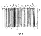
- the frame (111) presents first and second openings (111a 1 , 111a 2 ) for the passage of the gaseous reactants, respectively fuel and oxidant, first and second openings (111b 1 , 111b 2 ) for the discharge of the reaction products optionally mixed with exhausts, openings (112) for feeding and discharging a cooling fluid.
- the frame (11) is also provided with a multiplicity of holes (150) for housing tie-rods by means of which the electrochemical generator (100) is tightened.
- the frame (111) presents distributing channels (113a, 113b) (figure 5a) and cooling channels (114) (figure 5b), all obtained within the thickness of the frame itself.
- the distributing channels (113a) and (113b) are positioned at the interface with the central metallic body (110) and put the first and second openings (111a 1 , 111a 2 ) (only one of which is shown in figure 5a) and, respectively, the first and second openings (111b 1 , 111b 2 ) (only one of which is shown in figure 5a) in direct communication with the interior of the reaction cell (101) while the cooling channels (114) put the openings (112) in communication with the interior of the cooling cell (120).
- the coupling between openings (111a 1 , 111a 2 ) and openings (111b 1 , 111b 2 ) of all the frames (111) determines respectively the formation of two longitudinal manifolds (115) and two longitudinal manifolds (116), while the coupling between the openings (112) of all the frames (111) also determines the formation of relevant manifold, although they are not shown in figure 3 for the sake of simplicity.
- the two longitudinal manifolds (115), only one of which is shown in figure 3, are directed to feeding the gaseous reactants, the two longitudinal manifolds (116), only one of which is shown in figure 3, are directed to withdrawing the reaction products (water) optionally mixed with exhausts (gaseous inerts and unconverted fraction of reactants), the manifolds formed by the coupling of openings (112) are directed to feeding and extracting the cooling fluid.
- two terminal plates (117) are present (figure 3), delimiting the electrochemical generator (100).
- One of the two terminal plates (117) is provided with nozzles, not shown in figure 3, for the hydraulic connection of the various longitudinal manifolds to the external circuits.
- both of the terminal plates (117) are provided with appropriate holes (also not shown in figure 3) for housing the tie-rods.
- the central metallic body (110) of the bipolar sheets (192) may be provided with a multiplicity of calibrated holes (130a, 130b) with diameter comprised between 0.1 and 5 mm, as shown in figure 6.
- the multiplicity of calibrated holes (130a) and (130b) respectively, the gaseous reactants flow into the reaction cell (101) and the reaction products and exhausts are withdrawn from the same, as will be illustrated more in detail hereafter.
- the calibrated holes (130a) and (130b) have regularly varied diameters with the purpose of ensuring an equal distribution of gaseous reactants and withdrawal of products.
- the holes (130a) and (130b) are respectively positioned below and above the inner edges of frame (111) on the side opposite to that containing the distributing channels (131) and (132).
- the distance of the holes from the edges of frame (111) is preferably about 1 mm for a better exploitation of the reaction cell (101) active area.
- the frame (111) presents, on the side opposite to cooling cell (120), a distributing zone of gaseous reactants (131) in communication with first and second openings (111a 1 , 111a 2 ), and a collection zone of the reaction products and exhausts (132) in communication with first and second openings (111b 1 , 111b 2 ).
- the distributing zone of gaseous reactants (131) and the collection zone of the reaction products and exhausts (132) are both obtained within the thickness of the frame (111).
- the frame (111) On the side opposite to the reaction cell (101), the frame (111) is free of channels and its thickness on this side may be optimised as a function of the thickness of the membrane-electrode-collector assembly without further constraints.
- the distributing (131) and collection (132) zones are shown in figure 8, representing a front-view of the section of bipolar sheet (102) of figure 7 along the D-D plane. Channels (133) and (134) coincide with the alignment of holes (130a) and (130b).
- the electrochemical generator (100) operates as follows: the gaseous reactants (fuel and oxidant), which are supplied to the electrochemical generator (100) through the longitudinal manifolds (115), flow to the distributing zone (131), from here, the gaseous reactants flow across the channel (133) and through the multiplicity of calibrated holes (130a), and are injected into the reaction cell (101). The reaction products and exhausts produced therein pass in their tum through the multiplicity of calibrated holes (130b) and across the channel (134) reaching the collection zones (132) and the manifolds (116) through which they exit the electrochemical generator (100).
- the holes (130a) are used for injecting water directly into the reaction cell instead than for the injection of the gaseous reactants as seen above.
- the injected water plays a double role, namely providing for the humidification of the gases and the membrane (103) and for the withdrawal of the heat of reaction upon partially evaporating.
- the unevaporated water is extracted from the reaction cell together with the products and exhausts through the collection zone in communication with a longitudinal discharge manifold.
- the holes (130b) can therefore be eliminated.
- the section along the line C-C is represented, as regards this specific case, in figure 9, wherein the common parts with the previous figures are indicated with the same reference numbers.
- the section of the bipolar sheet of figure 9 along the line E-E is represented in figure 10, wherein the development of the channel (135) coinciding with holes (130a) and permitting the injection of water coming from (112) through the same is evidenced.
- the supply of reactant gases and the withdrawal of products and exhausts takes place, as indicated in figure 5a, through the channels (113a) and (113b).
- the thickness of the gasket (111) on the reaction cell side is limited by the necessity of housing the channels (113a) and (113b) and cannot be freely optimised as allowed by the embodiment of figure 7. It is possible to enjoy such advantage again, simultaneously making use of the effective direct water injection, by means of a further embodiment of the invention, characterised by resorting to a frame design encompassing the two concepts of gas distribution and water injection outlined in figures 7 and 9.
- a frame design encompassing the two concepts of gas distribution and water injection outlined in figures 7 and 9.
- Such embodiment is represented in figure 11 as a front-view of bipolar sheet (102) wherein the common parts with the previous figures are indicated with the same reference numbers.
- the central metallic body (110) is provided with a double row of holes, respectively 130a for feeding the gaseous reactants and (136) for injecting water, and with a single row of holes 130b directed to the withdrawal of reaction products, exhausts and residual water.
- the section of the frame (111) along the line F-F is represented in figure 12 showing the section of the distributing channel (135) of the water to be injected into the reaction cell (101) through the holes (136).
- a front-view of a further section of the bipolar sheet along the line G-G of figure 12 is shown in figure 13.
- bipolar sheets of the invention consisting of a central metallic body optionally provided with holes for distribution and collection and integrated with a frame of plastic material incorporating the different openings and channels may be achieved with one of the methods listed hereafter.
- the metallic body is preferably subjected to pretreatments such as fine sandblasting and/or chemical attacks, with the aim of producing a micro-rough and chemically reactive surface.
- pretreatments such as fine sandblasting and/or chemical attacks, with the aim of producing a micro-rough and chemically reactive surface.
- a further measure, equally directed to impart adhesion between metallic body and frame may consist of providing the metallic body with openings in the peripheral zone, wherein the frame material may penetrate during the moulding step thereby establishing a continuity between the two faces of the frame itself.
Landscapes
- Chemical & Material Sciences (AREA)
- Chemical Kinetics & Catalysis (AREA)
- General Chemical & Material Sciences (AREA)
- Sustainable Development (AREA)
- Sustainable Energy (AREA)
- Engineering & Computer Science (AREA)
- Life Sciences & Earth Sciences (AREA)
- Electrochemistry (AREA)
- Manufacturing & Machinery (AREA)
- Composite Materials (AREA)
- Fuel Cell (AREA)
- Electrolytic Production Of Non-Metals, Compounds, Apparatuses Therefor (AREA)
- Cell Separators (AREA)
- Separation Using Semi-Permeable Membranes (AREA)
- Manufacture Of Macromolecular Shaped Articles (AREA)
Claims (24)
- Elektrochemischer Membrangenerator, der durch gasförmige Reaktanten gespeist wird und umfasst:mehrere Reaktionszellen und mehrere zwischen den Reaktionszellen angeordnete Kühlzellen, die in einer Filterpressenanordnung montiert sind,wobei jede der Reaktionszellen durch Bipolarbleche begrenzt und mit metallischen netzartigen Stromsammlern/ -verteilern versehen ist,wobei jede der Kühlzellen durch Bipolarbleche begrenzt und mit einem netzartigen leitfähigen Element versehen ist,wobei die Bipolarbleche aus einem zentralen Metallkörper bestehen, dessen Abmessungen etwas größer als diejenigen der aktiven Fläche der Reaktionszellen sind und der in einen Rahmen aus einem Polymermaterial eingebaut ist,wobei der Rahmen mit ersten und zweiten Versorgungsöffnungen für den Durchlass der gasförmigen Reaktanten, ersten und zweiten Auslassöffnungen für den Abzug der Reaktionsprodukte, die gegebenenfalls mit Abgasen vermischt sind, und Öffnungen zur Zufuhr und Abfuhr eines Kühlmittels versehen ist und wobei der Rahmen Verteiler- und Sammelkanäle enthält, um eine direkte kommunizierende Verbindung zwischen den Öffnungen und den Reaktionszellen beziehungsweise den Kühlzellen herzustellen.
- Generator gemäß Anspruch 1, dadurch gekennzeichnet, dass das Polymermaterial ein thermoplastisches Material ist.
- Generator gemäß Anspruch 1, dadurch gekennzeichnet, dass das Polymermaterial ein duroplastisches Material ist.
- Generator gemäß einem der vorhergehenden Ansprüche, dadurch gekennzeichnet, dass der Rahmen durch Formen oder Verkleben mit dem zentralen Metallkörper verbunden ist.
- Generator gemäß Anspruch 4, dadurch gekennzeichnet, dass der zentrale Metallkörper vorab mit extrahierbaren Elementen versehen ist, welche die Form der Verteiler- und Sammelkanäle besitzen, und dass die extrahierbaren Elemente nach der Formgebung mit einem Reaktanten aufgelöst werden.
- Generator gemäß Anspruch 5, dadurch gekennzeichnet, dass die extrahierbaren Elemente aus Aluminium bestehen und der Reaktant Natronlauge ist.
- Generator gemäß Anspruch 4, dadurch gekennzeichnet, dass der zentrale Metallkörper vorab mit vorgeformten Elementen versehen wird, deren Form derjenigen der Verteiler- und Sammelkanäle entspricht.
- Generator gemäß Anspruch 7, dadurch gekennzeichnet, dass die vorgeformten Elemente aus Metall oder Kunststoffen bestehen.
- Generator gemäß Anspruch 8, dadurch gekennzeichnet, dass das Metall Edelstahl ist.
- Generator gemäß einem der Ansprüche 1 bis 3, dadurch gekennzeichnet, dass der mit dem zentralen Metallkörper integrale Rahmen aus zwei vorgeformten Komponenten besteht, welche die Verteiler- und Sammelkanäle enthalten.
- Generator gemäß Anspruch 10, dadurch gekennzeichnet, dass jeder der beiden vorgeformten Komponenten eine Fläche des Rahmens bildet.
- Generator gemäß einem der Ansprüche 10 oder 11, dadurch gekennzeichnet, dass die beiden Komponenten und der zentrale Metallkörper durch thermisches Verbinden oder Verkleben mit einem Klebstoff zusammengebaut werden.
- Generator gemäß einem der Ansprüche 4 oder 12, dadurch gekennzeichnet, dass der zentrale Metallkörper eine durch Sandstrahlen und/oder chemischen Angriff erhaltene mikroraue und/oder chemisch reaktive Oberfläche aufweist.
- Generator gemäß Anspruch 4, dadurch gekennzeichnet, dass der zentrale Metallkörper mit Öffnungen im Umfangsbereich versehen ist, welche der Verbesserung der Haftung des geformten Rahmens dienen.
- Generator gemäß einem der Ansprüche 1 bis 14, dadurch gekennzeichnet, dass bei einer Filterpressenanordnung die Kopplung zwischen den Öffnungen des Rahmens die Bildung von länglichen Versorgungssammelleitungen, die Kopplung zwischen den Auslassöffnungen die Bildung von länglichen Auslasssammelleitungen, die Kopplung zwischen den Öffnungen zum Zuführen und Abziehen des Kühlmittels die Bildung von Kühlmittelsammelleitungen bestimmt.
- Generator gemäß einem der Ansprüche 1 bis 15, dadurch gekennzeichnet, dass der Rahmen außerdem zahlreiche Löcher zur Aufnahme von Zugstangen aufweist, mittels derer das Zusammenziehen des elektrochemischen Generators bewirkt wird.
- Generator gemäß einem der vorhergehenden Ansprüche, dadurch gekennzeichnet, dass der zentrale Metallkörper zahlreiche erste kallibrierte Löcher für den Durchlass von gasförmigen Reaktanten und zahlreiche zweite kallibrierte Löcher für den Abzug der Reaktionsprodukte und gegebenenfalls enthaltener Abgase umfasst.
- Generator gemäß Anspruch 17, dadurch gekennzeichnet, dass die ersten kallibrierten Löcher gegenseitig ausgerichtet und entsprechend der Verteilerkanäle des Rahmens angeordnet sind und dass die zweiten kallibrierten Löcher gegenseitig ausgerichtet und entsprechend der Sammelkanäle des Rahmens angeordnet sind.
- Generator gemäß einem der Ansprüche 17 oder 18, dadurch gekennzeichnet, dass die ersten und zweiten kallibrierten Löcher etwa 1 mm vom inneren Rand des Rahmens beabstandet sind.
- Generator gemäß einem der Ansprüche 17 bis 19, dadurch gekennzeichnet, dass die ersten und zweiten kallibrierten Löcher einen Durchmesser zwischen 0,1 und 5 mm aufweisen.
- Generator gemäß einem der Ansprüche 1 bis 17, dadurch gekennzeichnet, dass der zentrale Metallkörper zahlreiche ausgerichtete kallibrierte Löcher zum Einspritzen von Wasser in die Reaktionszellen enthält, wobei die Löcher vorzugsweise etwa 1 mm von dem inneren Rand des Rahmens beabstandet sind.
- Generator gemäß Anspruch 21, dadurch gekennzeichnet, dass die ausgerichteten kallibrierten Löcher entsprechend zusätzlicher Wasserverteilerkanäle ausgerichtet sind.
- Generator gemäß einem der Ansprüche 1 bis 17, dadurch gekennzeichnet, dass der zentrale Körper zahlreiche ausgerichtete kallibrierte Löcher zum Verteilen der gasförmigen Reaktanten, zahlreiche ausgerichtete kallibrierte Löcher zum Einspritzen von Wasser und zahlreiche ausgerichtete kallibrierte Löcher zum Abziehen der Produkte, der Abgase und des restlichen eingespritzten Wassers umfasst, wobei jedes der kallibrierten Löcher entsprechend einem der Verteiler- oder Sammelkanäle ausgerichtet ist.
- Generator gemäß Anspruch 23, dadurch gekennzeichnet, dass die ausgerichteten kallibrierten Löcher zum Verteilen der gasförmigen Reaktionsteilnehmer und die ausgerichteten kallibrierten Löcher zum Abzug der Produkte, der Abgase und des restlichen eingespritzten Wassers etwa 1 mm vom inneren Rand des Rahmens beabstandet sind.
Applications Claiming Priority (3)
| Application Number | Priority Date | Filing Date | Title |
|---|---|---|---|
| ITMI20021859 | 2002-08-28 | ||
| IT001859A ITMI20021859A1 (it) | 2002-08-28 | 2002-08-28 | Generatore elettrochimico a membrana con migliorato |
| PCT/EP2003/009554 WO2004021490A1 (en) | 2002-08-28 | 2003-08-28 | Membrane electrochemical generator |
Publications (2)
| Publication Number | Publication Date |
|---|---|
| EP1547179A1 EP1547179A1 (de) | 2005-06-29 |
| EP1547179B1 true EP1547179B1 (de) | 2006-02-01 |
Family
ID=31972199
Family Applications (1)
| Application Number | Title | Priority Date | Filing Date |
|---|---|---|---|
| EP03790934A Expired - Lifetime EP1547179B1 (de) | 2002-08-28 | 2003-08-28 | Elektrochemischer membrangenerator |
Country Status (13)
| Country | Link |
|---|---|
| US (2) | US8062805B2 (de) |
| EP (1) | EP1547179B1 (de) |
| JP (1) | JP5043301B2 (de) |
| KR (1) | KR101056623B1 (de) |
| CN (1) | CN1679194A (de) |
| AT (1) | ATE317158T1 (de) |
| AU (1) | AU2003266319A1 (de) |
| BR (1) | BR0313926A (de) |
| CA (1) | CA2496046C (de) |
| DE (1) | DE60303459T2 (de) |
| ES (1) | ES2257704T3 (de) |
| IT (1) | ITMI20021859A1 (de) |
| WO (1) | WO2004021490A1 (de) |
Families Citing this family (5)
| Publication number | Priority date | Publication date | Assignee | Title |
|---|---|---|---|---|
| JP5151270B2 (ja) * | 2007-06-26 | 2013-02-27 | 日産自動車株式会社 | 燃料電池構成部材 |
| WO2014028859A1 (en) * | 2012-08-17 | 2014-02-20 | Nuvera Fuel Cells, Inc. | Design of bipolar plates for use in electrochemical cells |
| DK2730680T3 (en) | 2012-11-08 | 2016-07-25 | Siemens Ag | A cooling plate to an electrolyzer, electrolyzer and the process for the preparation of a bipolar plate |
| CN111971833A (zh) * | 2018-01-17 | 2020-11-20 | 努威拉燃料电池有限责任公司 | 燃料电池板和流动结构设计 |
| US20250266470A1 (en) * | 2022-04-07 | 2025-08-21 | Hysata Pty Ltd | Stackable electro-synthetic or electro-energy cells |
Family Cites Families (10)
| Publication number | Priority date | Publication date | Assignee | Title |
|---|---|---|---|---|
| US4678724A (en) * | 1982-06-23 | 1987-07-07 | United Technologies Corporation | Fuel cell battery with improved membrane cooling |
| GB8509957D0 (en) * | 1985-04-18 | 1985-05-30 | Ici Plc | Electrode |
| RU2174728C2 (ru) * | 1994-10-12 | 2001-10-10 | Х Пауэр Корпорейшн | Топливный элемент, использующий интегральную технологию пластин для распределения жидкости |
| JPH1074527A (ja) * | 1996-06-25 | 1998-03-17 | Du Pont Kk | 固体高分子電解質型燃料電池 |
| IT1312198B1 (it) * | 1999-04-21 | 2002-04-09 | De Nora Spa | Cella a combustibile raffreddata mediante iniezione diretta di acqualiquida |
| FR2810795B1 (fr) * | 2000-06-27 | 2002-10-04 | Technicatome | Plaque bipolaire a deux plaques metalliques pour pile a combustible et son procede de fabrication |
| JP3785909B2 (ja) | 2000-08-24 | 2006-06-14 | トヨタ自動車株式会社 | 燃料電池用セパレータの製造方法 |
| KR100397611B1 (ko) * | 2001-03-31 | 2003-09-17 | 삼성전자주식회사 | 수소이온교환 연료전지 스택 |
| GB0112021D0 (en) * | 2001-05-17 | 2001-07-11 | Johnson Matthey Plc | Substrate |
| CN1253957C (zh) * | 2001-08-16 | 2006-04-26 | 亚太燃料电池科技股份有限公司 | 燃料电池的双极板 |
-
2002
- 2002-08-28 IT IT001859A patent/ITMI20021859A1/it unknown
-
2003
- 2003-08-28 US US10/524,040 patent/US8062805B2/en active Active
- 2003-08-28 AU AU2003266319A patent/AU2003266319A1/en not_active Abandoned
- 2003-08-28 WO PCT/EP2003/009554 patent/WO2004021490A1/en not_active Ceased
- 2003-08-28 DE DE60303459T patent/DE60303459T2/de not_active Expired - Lifetime
- 2003-08-28 JP JP2004532136A patent/JP5043301B2/ja not_active Expired - Lifetime
- 2003-08-28 ES ES03790934T patent/ES2257704T3/es not_active Expired - Lifetime
- 2003-08-28 CN CNA038205629A patent/CN1679194A/zh active Pending
- 2003-08-28 AT AT03790934T patent/ATE317158T1/de not_active IP Right Cessation
- 2003-08-28 KR KR1020057003484A patent/KR101056623B1/ko not_active Expired - Lifetime
- 2003-08-28 BR BR0313926-3A patent/BR0313926A/pt not_active Application Discontinuation
- 2003-08-28 EP EP03790934A patent/EP1547179B1/de not_active Expired - Lifetime
- 2003-08-28 CA CA2496046A patent/CA2496046C/en not_active Expired - Lifetime
-
2010
- 2010-07-19 US US12/839,066 patent/US8592094B2/en not_active Expired - Lifetime
Also Published As
| Publication number | Publication date |
|---|---|
| ATE317158T1 (de) | 2006-02-15 |
| CA2496046A1 (en) | 2004-03-11 |
| ITMI20021859A1 (it) | 2004-02-29 |
| CA2496046C (en) | 2011-11-08 |
| JP5043301B2 (ja) | 2012-10-10 |
| US20080199747A1 (en) | 2008-08-21 |
| DE60303459D1 (de) | 2006-04-13 |
| EP1547179A1 (de) | 2005-06-29 |
| BR0313926A (pt) | 2005-07-12 |
| WO2004021490A1 (en) | 2004-03-11 |
| ES2257704T3 (es) | 2006-08-01 |
| AU2003266319A1 (en) | 2004-03-19 |
| KR20050057048A (ko) | 2005-06-16 |
| KR101056623B1 (ko) | 2011-08-16 |
| US20110033767A1 (en) | 2011-02-10 |
| US8062805B2 (en) | 2011-11-22 |
| DE60303459T2 (de) | 2006-09-28 |
| JP2005536863A (ja) | 2005-12-02 |
| US8592094B2 (en) | 2013-11-26 |
| CN1679194A (zh) | 2005-10-05 |
Similar Documents
| Publication | Publication Date | Title |
|---|---|---|
| US6322919B1 (en) | Fuel cell and bipolar plate for use with same | |
| US5486430A (en) | Internal fluid manifold assembly for an electrochemical fuel cell stack array | |
| US7824821B2 (en) | Fuel cell metallic separator | |
| US8580457B2 (en) | Fuel cell stack sealed with encapsulating material and method of making the same | |
| US8124292B2 (en) | Fuel cell stacks and methods | |
| EP2168185B1 (de) | Brennstoffzellenstapel und verfahren | |
| EP2492997B1 (de) | Bipolare platte für brennstoffzellen | |
| US8592094B2 (en) | Membrane electrochemical generator | |
| US7396609B2 (en) | Fuel cell and metal separator for fuel cell | |
| EP1504481B2 (de) | Elektrochemischer generator mit einer bipolarplatte, welche eine vielzahl von der verteilung der gase dienenden löchern aufweist | |
| KR100546016B1 (ko) | 연료전지용 전류집전체와 그 제조방법, 그리고 이를구비한 연료전지 | |
| JP2006100087A (ja) | 燃料電池 | |
| CN118213550A (zh) | 一种用于质子交换膜燃料电池的双极板及其制备方法 |
Legal Events
| Date | Code | Title | Description |
|---|---|---|---|
| PUAI | Public reference made under article 153(3) epc to a published international application that has entered the european phase |
Free format text: ORIGINAL CODE: 0009012 |
|
| 17P | Request for examination filed |
Effective date: 20050228 |
|
| AK | Designated contracting states |
Kind code of ref document: A1 Designated state(s): AT BE BG CH CY CZ DE DK EE ES FI FR GB GR HU IE IT LI LU MC NL PT RO SE SI SK TR |
|
| AX | Request for extension of the european patent |
Extension state: AL LT LV MK |
|
| GRAP | Despatch of communication of intention to grant a patent |
Free format text: ORIGINAL CODE: EPIDOSNIGR1 |
|
| GRAS | Grant fee paid |
Free format text: ORIGINAL CODE: EPIDOSNIGR3 |
|
| GRAA | (expected) grant |
Free format text: ORIGINAL CODE: 0009210 |
|
| DAX | Request for extension of the european patent (deleted) | ||
| AK | Designated contracting states |
Kind code of ref document: B1 Designated state(s): AT BE BG CH CY CZ DE DK EE ES FI FR GB GR HU IE IT LI LU MC NL PT RO SE SI SK TR |
|
| PG25 | Lapsed in a contracting state [announced via postgrant information from national office to epo] |
Ref country code: BE Free format text: LAPSE BECAUSE OF FAILURE TO SUBMIT A TRANSLATION OF THE DESCRIPTION OR TO PAY THE FEE WITHIN THE PRESCRIBED TIME-LIMIT Effective date: 20060201 Ref country code: AT Free format text: LAPSE BECAUSE OF FAILURE TO SUBMIT A TRANSLATION OF THE DESCRIPTION OR TO PAY THE FEE WITHIN THE PRESCRIBED TIME-LIMIT Effective date: 20060201 Ref country code: CH Free format text: LAPSE BECAUSE OF FAILURE TO SUBMIT A TRANSLATION OF THE DESCRIPTION OR TO PAY THE FEE WITHIN THE PRESCRIBED TIME-LIMIT Effective date: 20060201 Ref country code: SK Free format text: LAPSE BECAUSE OF FAILURE TO SUBMIT A TRANSLATION OF THE DESCRIPTION OR TO PAY THE FEE WITHIN THE PRESCRIBED TIME-LIMIT Effective date: 20060201 Ref country code: LI Free format text: LAPSE BECAUSE OF FAILURE TO SUBMIT A TRANSLATION OF THE DESCRIPTION OR TO PAY THE FEE WITHIN THE PRESCRIBED TIME-LIMIT Effective date: 20060201 Ref country code: FI Free format text: LAPSE BECAUSE OF FAILURE TO SUBMIT A TRANSLATION OF THE DESCRIPTION OR TO PAY THE FEE WITHIN THE PRESCRIBED TIME-LIMIT Effective date: 20060201 Ref country code: SI Free format text: LAPSE BECAUSE OF FAILURE TO SUBMIT A TRANSLATION OF THE DESCRIPTION OR TO PAY THE FEE WITHIN THE PRESCRIBED TIME-LIMIT Effective date: 20060201 Ref country code: RO Free format text: LAPSE BECAUSE OF FAILURE TO SUBMIT A TRANSLATION OF THE DESCRIPTION OR TO PAY THE FEE WITHIN THE PRESCRIBED TIME-LIMIT Effective date: 20060201 |
|
| REG | Reference to a national code |
Ref country code: GB Ref legal event code: FG4D |
|
| REG | Reference to a national code |
Ref country code: CH Ref legal event code: EP |
|
| REG | Reference to a national code |
Ref country code: IE Ref legal event code: FG4D |
|
| REF | Corresponds to: |
Ref document number: 60303459 Country of ref document: DE Date of ref document: 20060413 Kind code of ref document: P |
|
| PG25 | Lapsed in a contracting state [announced via postgrant information from national office to epo] |
Ref country code: BG Free format text: LAPSE BECAUSE OF FAILURE TO SUBMIT A TRANSLATION OF THE DESCRIPTION OR TO PAY THE FEE WITHIN THE PRESCRIBED TIME-LIMIT Effective date: 20060501 Ref country code: SE Free format text: LAPSE BECAUSE OF FAILURE TO SUBMIT A TRANSLATION OF THE DESCRIPTION OR TO PAY THE FEE WITHIN THE PRESCRIBED TIME-LIMIT Effective date: 20060501 Ref country code: DK Free format text: LAPSE BECAUSE OF FAILURE TO SUBMIT A TRANSLATION OF THE DESCRIPTION OR TO PAY THE FEE WITHIN THE PRESCRIBED TIME-LIMIT Effective date: 20060501 |
|
| PG25 | Lapsed in a contracting state [announced via postgrant information from national office to epo] |
Ref country code: PT Free format text: LAPSE BECAUSE OF FAILURE TO SUBMIT A TRANSLATION OF THE DESCRIPTION OR TO PAY THE FEE WITHIN THE PRESCRIBED TIME-LIMIT Effective date: 20060703 |
|
| REG | Reference to a national code |
Ref country code: ES Ref legal event code: FG2A Ref document number: 2257704 Country of ref document: ES Kind code of ref document: T3 |
|
| REG | Reference to a national code |
Ref country code: CH Ref legal event code: PL |
|
| PG25 | Lapsed in a contracting state [announced via postgrant information from national office to epo] |
Ref country code: IE Free format text: LAPSE BECAUSE OF NON-PAYMENT OF DUE FEES Effective date: 20060828 |
|
| PG25 | Lapsed in a contracting state [announced via postgrant information from national office to epo] |
Ref country code: MC Free format text: LAPSE BECAUSE OF NON-PAYMENT OF DUE FEES Effective date: 20060831 |
|
| ET | Fr: translation filed | ||
| PLBE | No opposition filed within time limit |
Free format text: ORIGINAL CODE: 0009261 |
|
| STAA | Information on the status of an ep patent application or granted ep patent |
Free format text: STATUS: NO OPPOSITION FILED WITHIN TIME LIMIT |
|
| 26N | No opposition filed |
Effective date: 20061103 |
|
| PG25 | Lapsed in a contracting state [announced via postgrant information from national office to epo] |
Ref country code: GR Free format text: LAPSE BECAUSE OF FAILURE TO SUBMIT A TRANSLATION OF THE DESCRIPTION OR TO PAY THE FEE WITHIN THE PRESCRIBED TIME-LIMIT Effective date: 20060502 Ref country code: CZ Free format text: LAPSE BECAUSE OF FAILURE TO SUBMIT A TRANSLATION OF THE DESCRIPTION OR TO PAY THE FEE WITHIN THE PRESCRIBED TIME-LIMIT Effective date: 20060201 Ref country code: NL Free format text: LAPSE BECAUSE OF NON-PAYMENT OF DUE FEES Effective date: 20080301 |
|
| NLV4 | Nl: lapsed or anulled due to non-payment of the annual fee |
Effective date: 20080301 |
|
| PG25 | Lapsed in a contracting state [announced via postgrant information from national office to epo] |
Ref country code: EE Free format text: LAPSE BECAUSE OF FAILURE TO SUBMIT A TRANSLATION OF THE DESCRIPTION OR TO PAY THE FEE WITHIN THE PRESCRIBED TIME-LIMIT Effective date: 20060201 |
|
| PG25 | Lapsed in a contracting state [announced via postgrant information from national office to epo] |
Ref country code: TR Free format text: LAPSE BECAUSE OF FAILURE TO SUBMIT A TRANSLATION OF THE DESCRIPTION OR TO PAY THE FEE WITHIN THE PRESCRIBED TIME-LIMIT Effective date: 20060201 Ref country code: HU Free format text: LAPSE BECAUSE OF FAILURE TO SUBMIT A TRANSLATION OF THE DESCRIPTION OR TO PAY THE FEE WITHIN THE PRESCRIBED TIME-LIMIT Effective date: 20060802 Ref country code: LU Free format text: LAPSE BECAUSE OF NON-PAYMENT OF DUE FEES Effective date: 20060828 |
|
| PG25 | Lapsed in a contracting state [announced via postgrant information from national office to epo] |
Ref country code: CY Free format text: LAPSE BECAUSE OF FAILURE TO SUBMIT A TRANSLATION OF THE DESCRIPTION OR TO PAY THE FEE WITHIN THE PRESCRIBED TIME-LIMIT Effective date: 20060201 |
|
| REG | Reference to a national code |
Ref country code: FR Ref legal event code: PLFP Year of fee payment: 14 |
|
| REG | Reference to a national code |
Ref country code: FR Ref legal event code: PLFP Year of fee payment: 15 |
|
| REG | Reference to a national code |
Ref country code: FR Ref legal event code: PLFP Year of fee payment: 16 |
|
| PGFP | Annual fee paid to national office [announced via postgrant information from national office to epo] |
Ref country code: IT Payment date: 20220630 Year of fee payment: 20 Ref country code: GB Payment date: 20220728 Year of fee payment: 20 Ref country code: ES Payment date: 20220914 Year of fee payment: 20 Ref country code: DE Payment date: 20220721 Year of fee payment: 20 |
|
| PGFP | Annual fee paid to national office [announced via postgrant information from national office to epo] |
Ref country code: FR Payment date: 20220718 Year of fee payment: 20 |
|
| REG | Reference to a national code |
Ref country code: DE Ref legal event code: R071 Ref document number: 60303459 Country of ref document: DE |
|
| REG | Reference to a national code |
Ref country code: ES Ref legal event code: FD2A Effective date: 20230904 |
|
| REG | Reference to a national code |
Ref country code: GB Ref legal event code: PE20 Expiry date: 20230827 |
|
| PG25 | Lapsed in a contracting state [announced via postgrant information from national office to epo] |
Ref country code: GB Free format text: LAPSE BECAUSE OF EXPIRATION OF PROTECTION Effective date: 20230827 Ref country code: ES Free format text: LAPSE BECAUSE OF EXPIRATION OF PROTECTION Effective date: 20230829 |