EP1546785B1 - Source de lumiere a large bande spectrale et a haute efficacite lumineuse - Google Patents
Source de lumiere a large bande spectrale et a haute efficacite lumineuse Download PDFInfo
- Publication number
- EP1546785B1 EP1546785B1 EP03807765A EP03807765A EP1546785B1 EP 1546785 B1 EP1546785 B1 EP 1546785B1 EP 03807765 A EP03807765 A EP 03807765A EP 03807765 A EP03807765 A EP 03807765A EP 1546785 B1 EP1546785 B1 EP 1546785B1
- Authority
- EP
- European Patent Office
- Prior art keywords
- fiber
- optical
- array
- light source
- leds
- Prior art date
- Legal status (The legal status is an assumption and is not a legal conclusion. Google has not performed a legal analysis and makes no representation as to the accuracy of the status listed.)
- Expired - Fee Related
Links
Images
Classifications
-
- G—PHYSICS
- G02—OPTICS
- G02B—OPTICAL ELEMENTS, SYSTEMS OR APPARATUS
- G02B6/00—Light guides; Structural details of arrangements comprising light guides and other optical elements, e.g. couplings
- G02B6/24—Coupling light guides
- G02B6/42—Coupling light guides with opto-electronic elements
- G02B6/4201—Packages, e.g. shape, construction, internal or external details
- G02B6/4249—Packages, e.g. shape, construction, internal or external details comprising arrays of active devices and fibres
-
- G—PHYSICS
- G02—OPTICS
- G02B—OPTICAL ELEMENTS, SYSTEMS OR APPARATUS
- G02B6/00—Light guides; Structural details of arrangements comprising light guides and other optical elements, e.g. couplings
- G02B6/24—Coupling light guides
- G02B6/42—Coupling light guides with opto-electronic elements
- G02B6/4201—Packages, e.g. shape, construction, internal or external details
- G02B6/4204—Packages, e.g. shape, construction, internal or external details the coupling comprising intermediate optical elements, e.g. lenses, holograms
- G02B6/4206—Optical features
Definitions
- the invention relates to a light source spectral broadband with high light output for fiber optic applications, in particular for use in fiber optic interferometers or fiber optic gyroscopes (FOGs).
- FOGs fiber optic gyroscopes
- the invention is therefore based on the object to provide a spectrally broadband light source of high light output for fiber optic applications available, which can be inexpensively manufactured in an economical automatic mass production process and thus in large quantities.
- a spectrally broadband light source with comparatively high light output for fiber optic applications, in particular for fiber optic sensors, is characterized by a monolithic linear array of adjacent surface emitting LEDs arranged on a substrate, in particular a wafer or chip, one in front of the monolithic LED linear array arranged on the emission side at a predetermined distance micro-optics with the LED elements individually assigned optical functions such that the radiation of the individual LEDs is focused on a for optimizing the optical fiber einkoppelbaren light power to a front of the coupling point of the fiber optic unit.
- the optical unit is formed as a ball lens disposed at a light irradiation end of the fiber.
- the invention is also advantageous for certain applications in metrology, especially in telecommunications, ie wherever a spectral broadband is needed, for. B. in the Surveying / measuring of WDM or DWDM systems.
- the actual light source is an array, preferably a lens array in combination with high performance, surface emitting LEDs. With these, the criterion of spectral broadband can be met. Such LEDs can be completely tested on the common wafer.
- the array consists of closely spaced adjacent LEDs on the wafer, the number of which is determined by the subsequent optical units for beam deflection and focusing as well as the required light output.
- a special micro-optic is mounted on the monolithic LED array. This consists of an array of individual optical functions in order to focus the more or less spatial radiation of the individual LEDs on the chip in a parallel emission. This summation of the individual light outputs of the individual LEDs fulfills the criterion of the desired high light output.
- the bundling takes place very precisely in adaptation to the individual LEDs of the array and is optionally optimized for each of these LEDs of the array with respect to the emission direction. These requirements can be realized very well with a micro-optic, namely monolithically in a single module.
- Another optical unit, z. B. on the fiber end face mounted ball lens is used for beam focusing and to optimize the coupling into the fiber.
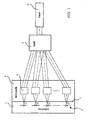
- a linear array of preferably equally spaced high-performance and surface-emitting LEDs are formed, which can all be tested directly on the wafer with known test methods.
- a lens array 4 of a micro-optics whose individual elements 4 are each aligned with one of the LEDs 3.
- the optical elements of the lens array 4 in turn are designed and aligned so that the light beams of the individual LED elements 3 are focused on a collection optics 5, which is preferably arranged in front of or on an optical fiber 6 collecting optics 5, for example, a ball lens.
Landscapes
- Physics & Mathematics (AREA)
- General Physics & Mathematics (AREA)
- Optics & Photonics (AREA)
- Optical Couplings Of Light Guides (AREA)
- Testing Or Measuring Of Semiconductors Or The Like (AREA)
- Led Device Packages (AREA)
- Instruments For Measurement Of Length By Optical Means (AREA)
- Investigating Materials By The Use Of Optical Means Adapted For Particular Applications (AREA)
Claims (2)
- Source de lumière à large bande spectrale et à haute efficacité lumineuse pour des utilisations par fibre optique, comportant- un réseau linéaire de LED adjacentes émettant superficiellement (3) disposé sur un substrat, en particulier une tranche ou une puce ;- un réseau micro optique (4) disposé à une distance prédéterminée du réseau linéaire de LED sur le côté de rayonnement comportant des fonctions optiques associées individuellement avec les éléments LED de sorte que le rayonnement des différentes LED est lié à une unité optique (5) utilisée pour l'optimisation de l'efficacité lumineuse pouvant être couplée dans une fibre optique (6), qui est disposée avant l'endroit de couplage de la fibre,caractérisée en ce que le réseau linéaire forme une unité monolithique et les différents éléments du réseau micro optique (4) sont disposés ou agencés de sorte que les rayons lumineux rayonnés par les éléments et dirigés vers l'unité optique présentent des angles d'inclinaison différents par rapport à l'axe longitudinal de la fibre.
- Source de lumière à large bande spectrale selon la revendication 1, caractérisée en ce que l'unité optique (5) est réalisée sous la forme d'une optique collectrice disposée à une extrémité de rayonnement lumineux de la fibre (6), en particulier sous la forme d'une lentille sphérique.
Applications Claiming Priority (3)
| Application Number | Priority Date | Filing Date | Title |
|---|---|---|---|
| DE10245526A DE10245526B4 (de) | 2002-09-30 | 2002-09-30 | Spektral breitbandige Lichtquelle hoher Lichtleistung |
| DE10245526 | 2002-09-30 | ||
| PCT/EP2003/008441 WO2004034112A1 (fr) | 2002-09-30 | 2003-07-30 | Source de lumiere a large bande spectrale et a haute efficacite lumineuse |
Publications (2)
| Publication Number | Publication Date |
|---|---|
| EP1546785A1 EP1546785A1 (fr) | 2005-06-29 |
| EP1546785B1 true EP1546785B1 (fr) | 2007-01-03 |
Family
ID=32009977
Family Applications (1)
| Application Number | Title | Priority Date | Filing Date |
|---|---|---|---|
| EP03807765A Expired - Fee Related EP1546785B1 (fr) | 2002-09-30 | 2003-07-30 | Source de lumiere a large bande spectrale et a haute efficacite lumineuse |
Country Status (4)
| Country | Link |
|---|---|
| US (1) | US20060056772A1 (fr) |
| EP (1) | EP1546785B1 (fr) |
| DE (2) | DE10245526B4 (fr) |
| WO (1) | WO2004034112A1 (fr) |
Families Citing this family (7)
| Publication number | Priority date | Publication date | Assignee | Title |
|---|---|---|---|---|
| DE10250912B4 (de) * | 2002-10-31 | 2006-04-27 | Osram Opto Semiconductors Gmbh | Einkoppelvorrichtung |
| WO2006032160A1 (fr) | 2004-09-21 | 2006-03-30 | Volpi Ag | Source d'eclairage |
| DE102005022175A1 (de) * | 2005-05-13 | 2006-12-21 | Carl Zeiss Jena Gmbh | Multispektrale Beleuchtungseinheit |
| DE102007027615B4 (de) * | 2007-06-12 | 2012-02-16 | Schott Ag | Vorrichtung zur Einkopplung von Licht in einen faseroptischen Lichtleiter |
| US9941965B2 (en) * | 2015-07-15 | 2018-04-10 | Flextronics Ap, Llc | Laser and optical charging and communications device and method of use |
| US9970746B2 (en) | 2015-08-26 | 2018-05-15 | Flextronics Ap, Llc | Diffusive optical fiber sensor and communication device and method of use |
| CN106526761A (zh) * | 2015-08-26 | 2017-03-22 | 弗莱克斯电子有限责任公司 | Led和激光光束耦合装置及其使用方法 |
Family Cites Families (13)
| Publication number | Priority date | Publication date | Assignee | Title |
|---|---|---|---|---|
| US90172A (en) * | 1869-05-18 | Improvement in horse-stall floors | ||
| US12047A (en) * | 1854-12-05 | Ester | ||
| US4185891A (en) * | 1977-11-30 | 1980-01-29 | Grumman Aerospace Corporation | Laser diode collimation optics |
| US4826269A (en) * | 1987-10-16 | 1989-05-02 | Spectra Diode Laboratories, Inc. | Diode laser arrangement forming bright image |
| JPH04255280A (ja) * | 1991-02-07 | 1992-09-10 | Nippon Steel Corp | 半導体レーザ励起固体レーザ装置 |
| US5268978A (en) * | 1992-12-18 | 1993-12-07 | Polaroid Corporation | Optical fiber laser and geometric coupler |
| US5513201A (en) * | 1993-04-30 | 1996-04-30 | Nippon Steel Corporation | Optical path rotating device used with linear array laser diode and laser apparatus applied therewith |
| JPH10503856A (ja) * | 1994-07-29 | 1998-04-07 | ポラロイド コーポレイション | 複数のビームを光学的に変換する装置 |
| JP3228098B2 (ja) * | 1995-11-01 | 2001-11-12 | 横河電機株式会社 | 光 源 |
| US5617492A (en) * | 1996-02-06 | 1997-04-01 | The Regents Of The University Of California | Fiber optic coupling of a microlens conditioned, stacked semiconductor laser diode array |
| US6577332B2 (en) * | 1997-09-12 | 2003-06-10 | Ricoh Company, Ltd. | Optical apparatus and method of manufacturing optical apparatus |
| US6654151B1 (en) * | 1999-06-25 | 2003-11-25 | Matsushita Electric Industrial Co., Ltd. | Image projector |
| JP2002202442A (ja) * | 2000-11-06 | 2002-07-19 | Fuji Photo Film Co Ltd | 合波レーザー光源および露光装置 |
-
2002
- 2002-09-30 DE DE10245526A patent/DE10245526B4/de not_active Expired - Fee Related
-
2003
- 2003-07-30 WO PCT/EP2003/008441 patent/WO2004034112A1/fr active IP Right Grant
- 2003-07-30 DE DE50306218T patent/DE50306218D1/de not_active Expired - Fee Related
- 2003-07-30 US US10/529,571 patent/US20060056772A1/en not_active Abandoned
- 2003-07-30 EP EP03807765A patent/EP1546785B1/fr not_active Expired - Fee Related
Also Published As
| Publication number | Publication date |
|---|---|
| DE50306218D1 (de) | 2007-02-15 |
| WO2004034112A1 (fr) | 2004-04-22 |
| DE10245526B4 (de) | 2005-05-12 |
| DE10245526A1 (de) | 2004-04-15 |
| US20060056772A1 (en) | 2006-03-16 |
| EP1546785A1 (fr) | 2005-06-29 |
Similar Documents
| Publication | Publication Date | Title |
|---|---|---|
| EP0114053B1 (fr) | Dispositif de détermination de la direction d'incidence d'un rayonnement optique | |
| DE19601955C2 (de) | Optoelektronische Sendebaugruppe | |
| DE102005031132B4 (de) | Optoelektronisches Modul mit hohem Kopplungswirkungsgrad | |
| EP2881031B1 (fr) | Endoscope, exoscope ou microscope et procédé d'éclairage d'une zone de commande d'un endoscope, exoscope ou microscope | |
| CN1249471C (zh) | 单通道m×n光纤开关 | |
| US6384612B2 (en) | Method and apparatus for testing the light output of light emitting devices | |
| EP2735025B1 (fr) | Module optoélectronique doté d'un système de lentilles | |
| DE60214186T2 (de) | Verfahren zur Herstellung von optischen Faserkollimatoren im Array | |
| KR20060049790A (ko) | 표면 조명 장치 | |
| EP1081819A3 (fr) | Sytème optique pour l'utilisation avec un système laser à diode et système laser à diode comprenant un tel sytème optique | |
| AT500056B8 (de) | Optikelement für verkehrszeichen, anzeigetafeln oder dgl. | |
| TW200746274A (en) | Laser irradiation device, laser irradiation method, and method for manufacturing modified object | |
| EP2735023A1 (fr) | Module optoélectronique à optique améliorée | |
| EP1546785B1 (fr) | Source de lumiere a large bande spectrale et a haute efficacite lumineuse | |
| WO2006080534B1 (fr) | Appareil optique d'eclairage et appareil optique | |
| DE19830360A1 (de) | Opto-elektronischer Modul | |
| DE102017109083A1 (de) | Beleuchtungsvorrichtung und Verfahren zur Herstellung einer Beleuchtungsvorrichtung | |
| EP0115267B1 (fr) | Système d'image | |
| DE10356384A1 (de) | Werkzeugbeleuchtungsvorrichtung | |
| US10400971B2 (en) | Lighting module with dioptric interface for motor vehicle | |
| DE102016124612A1 (de) | Segmentierte Optik für ein Beleuchtungsmodul zur winkelselektiven Beleuchtung | |
| CN103363442A (zh) | 透镜单元、光照射单元以及光照射装置 | |
| DE10001679A1 (de) | Optische Kopplungsanordnung | |
| DE102014204691A1 (de) | Bildaufnahmevorrichtung, insbesondere zur Fahrzeugvermessung | |
| DE60101452T2 (de) | Einstückiges optisches element zur lichttransmission und mehrkanaliger optischer modul mit diesen elementen |
Legal Events
| Date | Code | Title | Description |
|---|---|---|---|
| PUAI | Public reference made under article 153(3) epc to a published international application that has entered the european phase |
Free format text: ORIGINAL CODE: 0009012 |
|
| 17P | Request for examination filed |
Effective date: 20050126 |
|
| AK | Designated contracting states |
Kind code of ref document: A1 Designated state(s): AT BE BG CH CY CZ DE DK EE ES FI FR GB GR HU IE IT LI LU MC NL PT RO SE SI SK TR |
|
| RBV | Designated contracting states (corrected) |
Designated state(s): CZ DE FR GB |
|
| GRAP | Despatch of communication of intention to grant a patent |
Free format text: ORIGINAL CODE: EPIDOSNIGR1 |
|
| GRAS | Grant fee paid |
Free format text: ORIGINAL CODE: EPIDOSNIGR3 |
|
| GRAA | (expected) grant |
Free format text: ORIGINAL CODE: 0009210 |
|
| AK | Designated contracting states |
Kind code of ref document: B1 Designated state(s): CZ DE FR GB |
|
| REG | Reference to a national code |
Ref country code: GB Ref legal event code: FG4D Free format text: NOT ENGLISH |
|
| GBT | Gb: translation of ep patent filed (gb section 77(6)(a)/1977) |
Effective date: 20070124 |
|
| REF | Corresponds to: |
Ref document number: 50306218 Country of ref document: DE Date of ref document: 20070215 Kind code of ref document: P |
|
| ET | Fr: translation filed | ||
| PLBE | No opposition filed within time limit |
Free format text: ORIGINAL CODE: 0009261 |
|
| STAA | Information on the status of an ep patent application or granted ep patent |
Free format text: STATUS: NO OPPOSITION FILED WITHIN TIME LIMIT |
|
| 26N | No opposition filed |
Effective date: 20071005 |
|
| GBPC | Gb: european patent ceased through non-payment of renewal fee |
Effective date: 20070730 |
|
| PG25 | Lapsed in a contracting state [announced via postgrant information from national office to epo] |
Ref country code: DE Free format text: LAPSE BECAUSE OF NON-PAYMENT OF DUE FEES Effective date: 20080201 |
|
| PG25 | Lapsed in a contracting state [announced via postgrant information from national office to epo] |
Ref country code: CZ Free format text: LAPSE BECAUSE OF NON-PAYMENT OF DUE FEES Effective date: 20070730 Ref country code: GB Free format text: LAPSE BECAUSE OF NON-PAYMENT OF DUE FEES Effective date: 20070730 |
|
| REG | Reference to a national code |
Ref country code: FR Ref legal event code: ST Effective date: 20080331 |
|
| PG25 | Lapsed in a contracting state [announced via postgrant information from national office to epo] |
Ref country code: FR Free format text: LAPSE BECAUSE OF NON-PAYMENT OF DUE FEES Effective date: 20070731 |