EP1546541B1 - Elektronische vorrichtung zum konditionieren von brennstoff - Google Patents
Elektronische vorrichtung zum konditionieren von brennstoff Download PDFInfo
- Publication number
- EP1546541B1 EP1546541B1 EP03794742A EP03794742A EP1546541B1 EP 1546541 B1 EP1546541 B1 EP 1546541B1 EP 03794742 A EP03794742 A EP 03794742A EP 03794742 A EP03794742 A EP 03794742A EP 1546541 B1 EP1546541 B1 EP 1546541B1
- Authority
- EP
- European Patent Office
- Prior art keywords
- voltage
- conditioning device
- fuel conditioning
- electronic fuel
- circuit
- Prior art date
- Legal status (The legal status is an assumption and is not a legal conclusion. Google has not performed a legal analysis and makes no representation as to the accuracy of the status listed.)
- Expired - Lifetime
Links
- 239000000446 fuel Substances 0.000 title claims abstract description 76
- 230000003750 conditioning effect Effects 0.000 title claims abstract description 47
- 241000251730 Chondrichthyes Species 0.000 claims abstract description 24
- 238000002485 combustion reaction Methods 0.000 claims abstract description 15
- 239000003990 capacitor Substances 0.000 claims description 19
- 239000013078 crystal Substances 0.000 claims description 4
- 229910044991 metal oxide Inorganic materials 0.000 claims description 3
- 150000004706 metal oxides Chemical class 0.000 claims description 3
- 239000004065 semiconductor Substances 0.000 claims description 3
- 230000008878 coupling Effects 0.000 claims 2
- 238000010168 coupling process Methods 0.000 claims 2
- 238000005859 coupling reaction Methods 0.000 claims 2
- 238000001914 filtration Methods 0.000 claims 2
- 230000000087 stabilizing effect Effects 0.000 claims 1
- 238000010586 diagram Methods 0.000 description 7
- 230000004048 modification Effects 0.000 description 4
- 238000012986 modification Methods 0.000 description 4
- 238000010438 heat treatment Methods 0.000 description 3
- 230000001105 regulatory effect Effects 0.000 description 3
- 102100023882 Endoribonuclease ZC3H12A Human genes 0.000 description 2
- 101710112715 Endoribonuclease ZC3H12A Proteins 0.000 description 2
- 241001481828 Glyptocephalus cynoglossus Species 0.000 description 2
- ATUOYWHBWRKTHZ-UHFFFAOYSA-N Propane Chemical compound CCC ATUOYWHBWRKTHZ-UHFFFAOYSA-N 0.000 description 2
- 230000009977 dual effect Effects 0.000 description 2
- VNWKTOKETHGBQD-UHFFFAOYSA-N methane Chemical compound C VNWKTOKETHGBQD-UHFFFAOYSA-N 0.000 description 2
- QGVYYLZOAMMKAH-UHFFFAOYSA-N pegnivacogin Chemical compound COCCOC(=O)NCCCCC(NC(=O)OCCOC)C(=O)NCCCCCCOP(=O)(O)O QGVYYLZOAMMKAH-UHFFFAOYSA-N 0.000 description 2
- 239000000853 adhesive Substances 0.000 description 1
- 230000001070 adhesive effect Effects 0.000 description 1
- 230000003321 amplification Effects 0.000 description 1
- 239000004020 conductor Substances 0.000 description 1
- 230000001419 dependent effect Effects 0.000 description 1
- 230000000694 effects Effects 0.000 description 1
- 239000002828 fuel tank Substances 0.000 description 1
- 239000007789 gas Substances 0.000 description 1
- 239000010720 hydraulic oil Substances 0.000 description 1
- 238000009434 installation Methods 0.000 description 1
- JEIPFZHSYJVQDO-UHFFFAOYSA-N iron(III) oxide Inorganic materials O=[Fe]O[Fe]=O JEIPFZHSYJVQDO-UHFFFAOYSA-N 0.000 description 1
- 239000000463 material Substances 0.000 description 1
- 239000002184 metal Substances 0.000 description 1
- 239000003345 natural gas Substances 0.000 description 1
- 238000003199 nucleic acid amplification method Methods 0.000 description 1
- 230000010287 polarization Effects 0.000 description 1
- 239000001294 propane Substances 0.000 description 1
- 230000001681 protective effect Effects 0.000 description 1
- 238000005096 rolling process Methods 0.000 description 1
- XLYOFNOQVPJJNP-UHFFFAOYSA-N water Substances O XLYOFNOQVPJJNP-UHFFFAOYSA-N 0.000 description 1
- 238000004804 winding Methods 0.000 description 1
Images


Classifications
-
- F—MECHANICAL ENGINEERING; LIGHTING; HEATING; WEAPONS; BLASTING
- F02—COMBUSTION ENGINES; HOT-GAS OR COMBUSTION-PRODUCT ENGINE PLANTS
- F02M—SUPPLYING COMBUSTION ENGINES IN GENERAL WITH COMBUSTIBLE MIXTURES OR CONSTITUENTS THEREOF
- F02M27/00—Apparatus for treating combustion-air, fuel, or fuel-air mixture, by catalysts, electric means, magnetism, rays, sound waves, or the like
- F02M27/04—Apparatus for treating combustion-air, fuel, or fuel-air mixture, by catalysts, electric means, magnetism, rays, sound waves, or the like by electric means, ionisation, polarisation or magnetism
Definitions
- the present invention relates to a fuel conditioning device for improving the fuel efficiency and lowering pollution emissions of a fuel combustion machine.
- an electronic fuel conditioning device for attachment to a fuel line of a fuel combustion machine to improve combustion efficiency thereof, the device comprising:
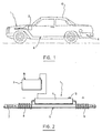
- a vehicle 10 provided with an internal combustion engine (not shown).
- the vehicle 10 has a fuel tank 6 that is connected to a fuel line 5 which is in turn connected to the combustion engine.
- a fuel conditioning device 1 according to a preferred embodiment of the present invention is installed on the existing fuel line 5 of the vehicle 10.
- the fuel conditioning device 1 is preferably powered by a 12 V battery 2 of the vehicle 10.
- the fuel conditioning device 1 may alternatively be powered by other means as persons skilled in the art will understand.
- the fuel conditioning device 1 according to the present invention may be used in different applications to improve fuel consumption efficiency of fuel combustion machines.
- a fuel conditioning device according to the present invention may also be installed in a fuel supply line of a heating system.
- the fuel conditioning device 1 has an electronic control box or housing 11 powered by the battery 2 in the case of the vehicle 10 shown in Figure 1, or by any other suitable power supply in the case of a heating system for example.
- Two conductor wires 8 and 9 come out from the housing 11 and are wound around the fuel line 5.
- the number of turns and the direction of rotation are dependent of the particular application. In case of a vehicle, the number of turns preferably ranges from 7 to 22.
- the windings 8 and 9 can be seen as a transformer primary, the fuel line 5 can be seen as the transformer core and the fuel 7 flowing through the fuel line 5 can be seen as the transformer secondary.
- the electronic fuel conditioning device 1 includes a frequency controlled signal generator 14 powered by a power supply 2.
- the frequency controlled signal generator 14 has a first output being connected to the first output wire 8 coiled around the fuel line 5 for producing a first shark dorsal waveform voltage signal 15 oscillating at a predetermined frequency.
- the frequency controlled signal generator 14 also has a second output connected to the second output wire 9 coiled around the fuel line 5 for producing a second shark dorsal waveform voltage signal 16 oscillating at the predetermined frequency.
- the second shark dorsal waveform voltage signal 16 is an inverted mirror signal of the first shark dorsal waveform voltage signal 15.
- the power supply 2 includes a vehicle battery 2 providing an input d.c. voltage of about 12 V.
- the frequency controlled signal generator 14 is housed in the housing 11 attached to the fuel line 5.
- the housing 11 may be attached or secured to the fuel line or placed in an adjacent position.
- the housing 11 may be provided with a light indicator 12 for providing an indication of operation of the electronic fuel conditioning device 1.
- the housing 11 may be made of plastic or metal, and contains the circuitry of the generator 14.
- This generator 14 may be split in three blocks which are inter-linked. All of this may be built over a printed circuit of approximately 1" ⁇ 2" (2.5 cm X 5cm) using integrated circuits of regular size which are easily available in the market. It may also be possible to use surface-mount type of materials, thus resulting in a smaller electronic fuel conditioning device.
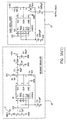
- FIG. 3A there is shown a block circuit diagram of internal elements of a fuel conditioning device 1 according to a first preferred embodiment of the present invention.
- a first element of the electronic fuel conditioning device 1 is a voltage doubler 20 which has an input that is connected to a d.c power source 2.
- the input may be connected to the 12 V vehicle battery 2 through diode D1 at the positive input of the power supply to protect it against polarity reversal.
- the input feeds the positive supply of all circuitry and is filtered by capacitor C1, which has a value of 1 ⁇ F in this example.
- the d.c. voltage at this point is labeled Vcc and has a value of about +12 V.
- An integrated circuit U1 (presently an LM555) is mounted as an astable oscillator.
- the resistors R1, R2 and capacitor C2 (having values of 10KoHm and 10 ⁇ F) determine the frequency of this oscillator (approximately 3 kHz).
- a square wave outputs at output pin 3 and couples via capacitor C3 at diodes D2 and D3. This output signal feeds a stocking capacitor C4, which filters the so created d.c. negative voltage, labeled Vss having a value of about -12 V.
- a second element of the electronic fuel conditioning device 1 is a main oscillator 22, which is built around circuit U2, which may be a LM555, (it may also work with a CD4046). It is an astable oscillator which frequency is determined by resistor R3 and capacitor C5 (having values of 10 Kohm and 0.002 ⁇ F).
- a potentiometer R4 is used as a frequency adjustment so as to adapt the generator 14 to the type of fuel, and/or the type of line on which the two output conducting wires 8 and 9 are wound.
- the wave produced resembles a shark dorsal on an oscilloscope and will output at pin 2 of the LM555 and sources a bi-polar amplifier 24, which is described below, via capacitor C7 and registers to resistor R6 (having values of 0.001 ⁇ F and 10 Kohm).
- the third element of the electronic fuel conditioning device 1 is the bi-polar amplifier 24. It is built around a dual operational amplifier composed of U3A and U3B, which may be embodied by a TL082. It is fed on a positive side by Vcc and on a negative side by Vss.
- the first amplifier is mounted as an inverting amplifier and its gain is determined by resistors R9 and R10 (100Kohm and 1Mohm), and feeds the negative output at coil L-, which represents the output wire 9.
- the second amplifier is mounted as non-inverting amplifier which gain is determined by resistors R7 and R8 (100Kohm and 1Mohm) and feeds the positive output at coil L+, which represents the first output wire 8. Both resistors R11 and R12 are used as current limiters to protect against accidental short circuits.
- an MOV metal oxide semiconductor
- the second modification is the use of an IC dedicated to voltage doubling, an ICL7662.
- the ICL7662 outputs a negative voltage that is more proportional to the positive input supply than the LM555 (U1) shown in Figure 3A. More stable, the ICL7662 is able to feed up to 100 mA comparatively to the configuration shown in Figure 3A that could give about 30 mA maximum.
- the third modification is the adding of a voltage regulator REG1 feeding the main oscillator circuit 22.
- the voltage regulator outputs 5 volts and is regulated whatever the incoming supply since this supply can vary, such as in the case of vehicle batteries, up to about 15 volts when the charging system is in function.
- the fourth modification is more of a practical order. It eliminates the use of the frequency adjustment's potentiometer R4 shown in Figure 3A. As shown in Figure 3B, four fixed value resistors in series R2, R3, R4 and R5 are installed with three of them being jumpers. When the unit is delivered, its frequency is 48 kHz. If one or more of the jumpers are cut, the frequency will then be of a new value out of four. These values are 26 kHz, 32 kHz, 36 kHz and 48 kHz.
- FIG. 3B there is shown a second preferred embodiment of internal elements of an electronic fuel conditioning device according to the present invention.
- the circuitry is split in three blocks which are inter-linked. All of this is built over a printed circuit of approximately one inch by two.
- the device may be built on a malleable printed circuit looking more like a small credit card but more flexible so that it can be installed by just rolling it over the conduit. This device could be covered with some adhesive with a protective film that may be removed just before the instalment so as to reduce the installation time.
- the first block is the voltage doubler 20.
- a diode D1 at the positive input of the power supply protects against polarity reversal. It feeds the positive supply of all circuitry and is filtered by capacitor C1. This voltage is labelled Vdd. Parallel to this supply, the metal oxide semiconductor MOV1 is used to protect the circuitry against surges that could be present on the 12 volts supply line.
- Capacitor C1 filters this Vdd line.
- a regulator REG1 outputs the 5 volts regulated to supply the positive voltage feeding the main oscillator 22 and is referred to as Vcc. This tension is stabilised by capacitor C6.
- An integrated circuit U2 (ICL7662) is used as a voltage doubler. Its input supply is stabilised by capacitor C2 and its negative output is stabilised by capacitor C3. This negative output is referred to as Vss.
- the second block is the main oscillator 22.
- the main oscillator is built around U1, an LM555, which is an astable oscillator. Its positive supply is connected to Vcc (5 volts regulated) and its negative supply goes directly to 0 volt, ground. Its frequency is determined by the R1 resistor and capacitor C4 and also the resistor network composed of R2, R3, R4 and R5.
- the three last resistors are bypassed with three jumpers witch are labelled J1, J2 and J3, meaning that the device, when delivered, is tuned to 48 kHz. To get it down to 36 kHz, one needs to cut jumper J1. If one wants 32 kHz, one needs to cut also jumper J2 and for 26 kHz, then one also cuts jumper J3.
- the wave produced resembles a shark dorsal on an oscilloscope and outputs at pin 2 of the LM555 integrated circuit and sources the bi-polarity amplifier 24 via capacitor C5 and registers to resistor R6.
- Integrated circuit U1 of type «Fox crystal oscillator» feeds the clock input of U5, (CD4017) and its output sources the bi-polar amplifier 24.
- the bi-polar amplifier 24 and the voltage doubler 20 stay the same as the above.
- the third block, or bi-polar amplifier 24 is built around a dual operational amplifier composed of U3A and U3B.
- the bi-polar amplifier 24, which may be a TL082 is fed on positive side by Vdd (+12 volt nominal) and negative side by Vss (-12 volt nominal).
- the first amplifier is mounted as an inverting amplifier and its gain is determined by resistors R9 and R10 and feeds the negative output at coil L-, which is representative of output wire 9.
- the second one is mounted as non-inverting amplifier witch gain is determined by resistors R7 and R8 and feeds the positive output at coil L+, which is representative of output wire 8.
- Both resistors R11 and R12 are used as a current limiter to protect against accidental short-circuit. The negative supply being more stable, the negative output completes more accurately the positive.
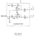
- one other improvement consists in using a microprocessor as the main oscillator 22. It should be noted that the power supply 2, the voltage doubler 20 and the bi-polar amplifier 24 are not changed from the design described above.
- the microprocessor is referred to as U1. Its working frequency is 10 MHz and is determined by crystal Y1.
- the IO4 input is connected to the junction of R10 and OPT1.
- This ensemble is an infrared detector and is used as the exterior world communication channel. Through this channel, one can input the choice of parameter so that the system may be adapted to the environment as far as the type of combustible and the type of piping used. It should be noted that a handheld type of IR transmitter allows the installer to communicate with the module so to adapt this module.
- Line IO3 is connected to the junction of capacitor C7, resistor R11 and temperature transducer TS1.
- the output labelled IO2 drives transistor Q1 which is connected from resistor R8 to ground. This circuit adapts the impedance depending on output frequency. Transistor Q2 is connected to capacitor C5. The IO0 output tied to resistor R9, followed by C4 to ground corrects, with the preceding circuit, the waveform depending on preprogrammed parameters. This ensemble becomes the output frequency which sources the bi-polar amplifier.
- the fuel conditioning device according to the present invention may be used in many applications such as propane gas systems, natural gas systems, water conditioning systems, air systems, hydraulic oil systems, etc. It has also been observed that the fuel conditioning device may produce a counter effect over rust in several components of a vehicle.
Landscapes
- Engineering & Computer Science (AREA)
- Chemical & Material Sciences (AREA)
- Chemical Kinetics & Catalysis (AREA)
- Combustion & Propulsion (AREA)
- Mechanical Engineering (AREA)
- General Engineering & Computer Science (AREA)
- Dc-Dc Converters (AREA)
- Amplifiers (AREA)
- Control Of Eletrric Generators (AREA)
- Electrical Control Of Air Or Fuel Supplied To Internal-Combustion Engine (AREA)
- Fuel-Injection Apparatus (AREA)
- Combined Controls Of Internal Combustion Engines (AREA)
- Feeding And Controlling Fuel (AREA)
- Air-Conditioning For Vehicles (AREA)
Claims (15)
- Ein elektronisches Brennstoffaufbereitungsgerät (1) zum Anbringen einer Kraftstoffleitung (5) einer Kraftstoffverbrennungsmaschine, um den Feuerungswirkungsgrad dieser zu verbessern, bestehend aus:einem frequenzgesteuerten Signalgeber (14), angetrieben von einer Stromversorgung (2), der frequenzgesteuerte Signalgenerator (14) hat eine erste Ausgabe, die an die Ausgangsleitung angeschlossen ist (8), die um die Kraftstoffleitung (5) gespult ist, um ein erstes Spannungssignal (15) zu erzeugen, das bei einer vorbestimmten Frequenz schwingt, und eine zweite Ausgabe, angeschlossen an eine zweite Ausgangsleitung (9), die um die Kraftstoffleitung gespult ist (5), um das zweite Spannungssignal (16) zu erzeugen, das bei einer vorbestimmten Frequenz schwingt und durch die Tatsache charakterisiert wird, dass das erste (15) und zweite (16) Spaonuogssignal, ein Signal in einer Wellenform einer Haifischrückenflosse sind; das zweite Spannungssignal in einer Wellenform einer Haifischrückenflosse (16) ist ein umgedrehtes Wiedergabesignal des Spannungssignals in einer Wellenform einer Haifischrückenflosse (15).
- Das elektronische Brennstoffaufbereitungsgerät (1), entsprechend des 1 Anspruchs, bei dem die Stromversorgung (2) eine Autobatterie einschließt, welche die Eingangsgleichspannung von 12 V bietet und wobei sich der frequenzgesteuerte Signalgenerator (14) in einem Gehäuse (11) befindet, das mit der Kraftstoffleitung (5) verbunden ist.
- Das elektronische Brennstoffaufbereitungsgerät (1), entsprechend des 1 Anspruchs, worin der frequenzgesteuerte Signalgenerator (14) folgendes einschließt:einen Hauptoszillatorschaltkreis (22) zum Erzeugen einer Wellenform einer Haifischrückenflosse, die bei einer vorbestimmten Wellenform schwingt;einen zweipoligen Verstärker (24), gekoppelt mit einem Hauptoszillatorschaltkreis (22), um das erste und zweite Spannungssignal in einer Wellenform einer Haifischrückenflosse (15, 16) zu erzeugen; undeinen Spannungsverdopplerschaltkreis (20) zum Betreiben des zweipoligen Verstärkerschaltkreises (24) mit positiver und negativer Gleichspannung.
- Das elektronische Brennstoffaufbereitungsgerät (1), entsprechend des 3 Anspruchs, bei dem der Spannungsverdopplerschaltkreis (20) eine Eingangsdiode (D1) zum Schutz gegen Zustandsänderung und einen Filterkondensator (C1) zum Filtern und Stabilisieren der Eingangsgleichspannung enthält.
- Das elektronische Brennstoffaufbereitungsgerät (1), entsprechend des 4 Anspruchs, wobei der Spannungsverdopplerschaltkreis (20) einen instabilen integrierten Oszillatorschaltkreis (U1) mit Ausgang hat, der an einen Kondensator und Diodenschaltkreis (C3, C4, D2, D3) zum Erzeugen von negativer Gleichspannung angeschlossen ist.
- Das elektronische Brennstoffaufbereitungsgerät (1), entsprechend des 5 Anspruchs, wobei der Hauptoszillatorschaltkreis (22) einen instabilen integrierten LM555 Hauptoszillatorschaltkreis (U2) einschließt, der an den Widerstand (R3), einen variablen Widerstand (R4) und einen Kondensator (C5) zum Anpassen der vorbestimmten Frequenz angeschlossen ist, und einen Auslöserkontakt des instabilen integrierten LM555 Hauptoszillatorschaltkreises (U2) zum Anschließen des Eingangs des zweipoligen Verstärkers (24) durch einen Kupplungskondensator (C7) und einen Kupplungswiderstand (R6) hat.
- Das elektronische Brennstoffaufbereitungsgerät (1), entsprechend des 6 Anspruchs, wobei der zweipolige Verstärker (24) einen integrierten TL082 Schaltkreis einschließt, der einen ersten nicht invertierenden Verstärker zum Erzeugen des ersten und zweiten Spannungssignals in einer Wellenform einer Haifischrückenflosse (15, 16) hat.
- Das elektronische Brennstoffaufbereitungsgerät (1), entsprechend des 4 Anspruchs, wobei der Spannungsverdopplerschaltkreis (20) femer einen Metalloxidhalbleiter zum Schutz gegen Spannungsstoß des eingehenden Gleichstroms enthält.
- Das elektronische Brennstoffaufbereitungsgerät (1), entsprechend des 8 Anspruchs, wobei der Spannungsverdopplerschaltkreis (20) femer einen integrierten ICL 7662 Schaltkreis zum Erzeugen der negativen Gleichspannung enthält.
- Das elektronische Brennstoffaufbereitungsgerät (1), entsprechend des 9 Anspruchs, wobei der Spannungsverdopplerschaltkreis (20) femer einen Spannungsregler (REG1) zum Speisen des Hauptoszillatorschaltkreises (22) enthält.
- Das elektronische Brennstoffaufbereitungsgerät (1), entsprechend des 10 Anspruchs, wobei der Hauptoszillatorschaltkreis (22) einen Satz von drei elektrischen Widerständen (R3, R4, R5) zum Anpassen der vorbestimmten Frequenz enthält.
- Das elektronische Brennstoffaufbereitungsgerät (1), entsprechend des 11 Anspruchs, wobei die vorbestimmte Frequenz an 48 kHz, 36 kHz, 32 kHz oder 26 kHz entsprechend des Brückenwiderstands (R3, R4, R5) angepasst wird.
- Das elektronische Brennstoffaufbereitungsgerät (1), entsprechend des 11 Anspruchs, wobei der Hauptoszillatorschaltkreis (22) einen Kristalloszillatorschaltkreis zum Speisen eines Takteingangs eines integrierten CD4017 Schaltkreises enthält, der einen Ausgang zum Speisen des zweipoligen Verstärkers (24) hat.
- Das elektronische Brennstoffaufbereitungsgerät (1), entsprechend des 13 Anspruchs, wobei der Hauptoszillatorschaltkreis (22) einen Mikroprozessor enthält, der an einen infraroten Detektor angeschlossen ist, und einen Kommunikationskanal zum Steuern der vorbestimmten Frequenz, der Amplituden und Formen der ersten und zweiten Spannungssignale in einer Wellenform einer Haifischrückenflosse (15, 16) verwendet.
- Das elektronische Brennstoffaufbereitungsgerät (1), entsprechend des 13 Anspruchs, wobei der Hauptoszillatorschaltkreis (22) einen Temperatursensor zum Erlangen des Temperaturwerts einschließt, der zum Korrigieren der vorbestimmten Frequenz der Amplituden und Formen der ersten und zweiten Spannungssignal in einer Wellenform einer Haifischrückenflosse (15, 16) verwendet werden.
Applications Claiming Priority (3)
| Application Number | Priority Date | Filing Date | Title |
|---|---|---|---|
| CA002403049A CA2403049A1 (en) | 2002-09-13 | 2002-09-13 | Electronic fuel conditioning system |
| CA2403049 | 2002-09-13 | ||
| PCT/CA2003/001402 WO2004025110A1 (en) | 2002-09-13 | 2003-09-15 | Electronic fuel conditioning device |
Publications (2)
| Publication Number | Publication Date |
|---|---|
| EP1546541A1 EP1546541A1 (de) | 2005-06-29 |
| EP1546541B1 true EP1546541B1 (de) | 2006-03-15 |
Family
ID=31983626
Family Applications (1)
| Application Number | Title | Priority Date | Filing Date |
|---|---|---|---|
| EP03794742A Expired - Lifetime EP1546541B1 (de) | 2002-09-13 | 2003-09-15 | Elektronische vorrichtung zum konditionieren von brennstoff |
Country Status (9)
| Country | Link |
|---|---|
| US (1) | US6971376B2 (de) |
| EP (1) | EP1546541B1 (de) |
| AT (1) | ATE320554T1 (de) |
| AU (1) | AU2003266085A1 (de) |
| CA (1) | CA2403049A1 (de) |
| DE (1) | DE60304062T2 (de) |
| ES (1) | ES2262015T3 (de) |
| MX (1) | MXPA05002795A (de) |
| WO (1) | WO2004025110A1 (de) |
Cited By (1)
| Publication number | Priority date | Publication date | Assignee | Title |
|---|---|---|---|---|
| RU2596086C2 (ru) * | 2015-01-12 | 2016-08-27 | Федеральное государственное бюджетное образовательное учреждение высшего образования "Государственный университет морского и речного флота имени адмирала С.О. Макарова" | Устройство для магнитной обработки углеводородного топлива в теплоэнергетических установках |
Families Citing this family (8)
| Publication number | Priority date | Publication date | Assignee | Title |
|---|---|---|---|---|
| US7341446B2 (en) * | 2004-04-02 | 2008-03-11 | Bush Gary L | Nuclear resonance applications for enhanced combustion |
| FR2895029A1 (fr) * | 2005-12-20 | 2007-06-22 | Den Hende Fabrice Van | Optimisation de carburant et autres combustibles par induction electromagnetique modulee en frequence |
| US7418955B1 (en) | 2006-07-09 | 2008-09-02 | James Dwayne Hankins | Fuel savings device and methods of making the same |
| US8025044B1 (en) | 2006-07-09 | 2011-09-27 | James Dwayne Hankins | Fuel savings device and methods of making the same |
| DE102007063064A1 (de) | 2007-12-21 | 2009-06-25 | Aloys Wobben | Verfahren zur Vermeidung und/oder zum Verringern von Schadstoffanteilen im Abgas einer Verbrennungsmaschine |
| US8408185B1 (en) * | 2008-11-26 | 2013-04-02 | Harvey G. Kiker | Engine fuel economizer |
| JP2014505819A (ja) * | 2010-12-07 | 2014-03-06 | ザヴァラス、イリアス | 炭化水素燃焼の最適化装置 |
| US11635048B2 (en) * | 2019-10-02 | 2023-04-25 | Tokyomirai Co., Ltd. | Energy conversion efficiency improvement device |
Family Cites Families (8)
| Publication number | Priority date | Publication date | Assignee | Title |
|---|---|---|---|---|
| US3976726A (en) * | 1974-02-11 | 1976-08-24 | Electro Fuel, Inc. | Fuel activation apparatus |
| US5048498A (en) * | 1990-08-10 | 1991-09-17 | Alan Cardan | Fuel line conditioning apparatus |
| US5134985A (en) * | 1991-01-28 | 1992-08-04 | Rao Velagapudi M | Burner fuel line enhancement device |
| JP2646340B2 (ja) * | 1994-11-22 | 1997-08-27 | 株式会社国際技研 | 内燃機関用燃料の清浄装置 |
| DE19732834A1 (de) * | 1997-07-30 | 1999-02-04 | Reika Elektronik Karin Walch | Vorrichtung zur Behandlung von flüssigen oder gasförmigen Brennstoffen |
| WO2000015957A1 (en) | 1998-09-15 | 2000-03-23 | Chauffa-Tech | Fuel conditioning device for ionizing hydrocarbon fuel in internal combustion engines |
| IT1314789B1 (it) * | 2000-02-09 | 2003-01-16 | E Col Energy Srl | Dispositivo e procedimento per ottimizzare la combustione diidrocarburi. |
| GB2366223B (en) * | 2000-08-23 | 2004-01-21 | Jacques Prevost | Electrostatic fluid conditioner |
-
2002
- 2002-09-13 CA CA002403049A patent/CA2403049A1/en not_active Abandoned
-
2003
- 2003-09-15 DE DE60304062T patent/DE60304062T2/de not_active Expired - Lifetime
- 2003-09-15 AT AT03794742T patent/ATE320554T1/de not_active IP Right Cessation
- 2003-09-15 AU AU2003266085A patent/AU2003266085A1/en not_active Abandoned
- 2003-09-15 EP EP03794742A patent/EP1546541B1/de not_active Expired - Lifetime
- 2003-09-15 MX MXPA05002795A patent/MXPA05002795A/es active IP Right Grant
- 2003-09-15 WO PCT/CA2003/001402 patent/WO2004025110A1/en not_active Ceased
- 2003-09-15 ES ES03794742T patent/ES2262015T3/es not_active Expired - Lifetime
- 2003-09-15 US US10/494,809 patent/US6971376B2/en not_active Expired - Fee Related
Cited By (1)
| Publication number | Priority date | Publication date | Assignee | Title |
|---|---|---|---|---|
| RU2596086C2 (ru) * | 2015-01-12 | 2016-08-27 | Федеральное государственное бюджетное образовательное учреждение высшего образования "Государственный университет морского и речного флота имени адмирала С.О. Макарова" | Устройство для магнитной обработки углеводородного топлива в теплоэнергетических установках |
Also Published As
| Publication number | Publication date |
|---|---|
| WO2004025110A1 (en) | 2004-03-25 |
| US20050016508A1 (en) | 2005-01-27 |
| US6971376B2 (en) | 2005-12-06 |
| DE60304062T2 (de) | 2006-11-09 |
| AU2003266085A1 (en) | 2004-04-30 |
| ES2262015T3 (es) | 2006-11-16 |
| CA2403049A1 (en) | 2004-03-13 |
| ATE320554T1 (de) | 2006-04-15 |
| DE60304062D1 (de) | 2006-05-11 |
| EP1546541A1 (de) | 2005-06-29 |
| MXPA05002795A (es) | 2005-06-03 |
Similar Documents
| Publication | Publication Date | Title |
|---|---|---|
| EP1546541B1 (de) | Elektronische vorrichtung zum konditionieren von brennstoff | |
| Trigui et al. | Inductive power transfer system with self-calibrated primary resonant frequency | |
| US6758199B2 (en) | Tuned power ignition system | |
| US5150683A (en) | Flexible fuel sensor system | |
| IT1208855B (it) | Sistema di accensione ad energia di scintilla variabile per motori acombustione interna particolarmente per autoveicoli | |
| US6650232B1 (en) | Sounder control system | |
| CA2496564C (en) | Electronic fuel conditioning device | |
| CA2388697C (en) | Electrostatic fluid conditioner | |
| CA1101518A (en) | 5,000 hour blocking oscillator for an electromagnetic fuel pump | |
| US20070114164A1 (en) | Pulse resonating device | |
| CN109844302B (zh) | 用于轻型燃烧发动机的控制和通信模块 | |
| GB2067295A (en) | Proximity detector | |
| FR2701105B1 (fr) | Dispositif de déminage. | |
| CA2295524C (en) | Fuel conditioning device for ionizing hydrocarbon fuel in internal combustion engines | |
| EP1387084A3 (de) | Induktives Zündsystem mit digitaler Regelung | |
| FR2468886A1 (fr) | Installation inductive de mesure pour detecter la course d'un organe de commande ou de regulation, notamment dans un moteur a combustion interne | |
| US5144232A (en) | Testing device for an electric generator | |
| GB2290110A (en) | Electromagnetic fuel treatment | |
| US3958791A (en) | Ignition system and components thereof | |
| EP1705370A3 (de) | Induktives Zündsteuerungssystem | |
| SU454657A1 (ru) | Электрический регул тор частоты электроагрегатов переменного тока | |
| US6172887B1 (en) | Circuit for supplying power, without the need for a battery, to the electronic control unit of a machine driven by an internal-combustion engine | |
| JPS61134532A (ja) | 超音波霧化器駆動回路 | |
| SU463951A1 (ru) | Устройство дл регулировани числа оборотов карбюраторного двигател | |
| JPH11132453A (ja) | フレームロッド回路 |
Legal Events
| Date | Code | Title | Description |
|---|---|---|---|
| PUAI | Public reference made under article 153(3) epc to a published international application that has entered the european phase |
Free format text: ORIGINAL CODE: 0009012 |
|
| 17P | Request for examination filed |
Effective date: 20050401 |
|
| AK | Designated contracting states |
Kind code of ref document: A1 Designated state(s): AT BE BG CH CY CZ DE DK EE ES FI FR GB GR HU IE IT LI LU MC NL PT RO SE SI SK TR |
|
| AX | Request for extension of the european patent |
Extension state: AL LT LV MK |
|
| GRAP | Despatch of communication of intention to grant a patent |
Free format text: ORIGINAL CODE: EPIDOSNIGR1 |
|
| DAX | Request for extension of the european patent (deleted) | ||
| GRAS | Grant fee paid |
Free format text: ORIGINAL CODE: EPIDOSNIGR3 |
|
| GRAA | (expected) grant |
Free format text: ORIGINAL CODE: 0009210 |
|
| AK | Designated contracting states |
Kind code of ref document: B1 Designated state(s): AT BE BG CH CY CZ DE DK EE ES FI FR GB GR HU IE IT LI LU MC NL PT RO SE SI SK TR |
|
| PG25 | Lapsed in a contracting state [announced via postgrant information from national office to epo] |
Ref country code: NL Free format text: LAPSE BECAUSE OF FAILURE TO SUBMIT A TRANSLATION OF THE DESCRIPTION OR TO PAY THE FEE WITHIN THE PRESCRIBED TIME-LIMIT Effective date: 20060315 Ref country code: SK Free format text: LAPSE BECAUSE OF FAILURE TO SUBMIT A TRANSLATION OF THE DESCRIPTION OR TO PAY THE FEE WITHIN THE PRESCRIBED TIME-LIMIT Effective date: 20060315 Ref country code: AT Free format text: LAPSE BECAUSE OF FAILURE TO SUBMIT A TRANSLATION OF THE DESCRIPTION OR TO PAY THE FEE WITHIN THE PRESCRIBED TIME-LIMIT Effective date: 20060315 Ref country code: SI Free format text: LAPSE BECAUSE OF FAILURE TO SUBMIT A TRANSLATION OF THE DESCRIPTION OR TO PAY THE FEE WITHIN THE PRESCRIBED TIME-LIMIT Effective date: 20060315 Ref country code: BE Free format text: LAPSE BECAUSE OF FAILURE TO SUBMIT A TRANSLATION OF THE DESCRIPTION OR TO PAY THE FEE WITHIN THE PRESCRIBED TIME-LIMIT Effective date: 20060315 Ref country code: CH Free format text: LAPSE BECAUSE OF FAILURE TO SUBMIT A TRANSLATION OF THE DESCRIPTION OR TO PAY THE FEE WITHIN THE PRESCRIBED TIME-LIMIT Effective date: 20060315 Ref country code: FI Free format text: LAPSE BECAUSE OF FAILURE TO SUBMIT A TRANSLATION OF THE DESCRIPTION OR TO PAY THE FEE WITHIN THE PRESCRIBED TIME-LIMIT Effective date: 20060315 Ref country code: LI Free format text: LAPSE BECAUSE OF FAILURE TO SUBMIT A TRANSLATION OF THE DESCRIPTION OR TO PAY THE FEE WITHIN THE PRESCRIBED TIME-LIMIT Effective date: 20060315 |
|
| REG | Reference to a national code |
Ref country code: CH Ref legal event code: EP Ref country code: GB Ref legal event code: FG4D |
|
| REG | Reference to a national code |
Ref country code: IE Ref legal event code: FG4D |
|
| REF | Corresponds to: |
Ref document number: 60304062 Country of ref document: DE Date of ref document: 20060511 Kind code of ref document: P |
|
| REG | Reference to a national code |
Ref country code: RO Ref legal event code: EPE |
|
| PG25 | Lapsed in a contracting state [announced via postgrant information from national office to epo] |
Ref country code: DK Free format text: LAPSE BECAUSE OF FAILURE TO SUBMIT A TRANSLATION OF THE DESCRIPTION OR TO PAY THE FEE WITHIN THE PRESCRIBED TIME-LIMIT Effective date: 20060615 Ref country code: BG Free format text: LAPSE BECAUSE OF FAILURE TO SUBMIT A TRANSLATION OF THE DESCRIPTION OR TO PAY THE FEE WITHIN THE PRESCRIBED TIME-LIMIT Effective date: 20060615 |
|
| REG | Reference to a national code |
Ref country code: SE Ref legal event code: TRGR |
|
| PG25 | Lapsed in a contracting state [announced via postgrant information from national office to epo] |
Ref country code: PT Free format text: LAPSE BECAUSE OF FAILURE TO SUBMIT A TRANSLATION OF THE DESCRIPTION OR TO PAY THE FEE WITHIN THE PRESCRIBED TIME-LIMIT Effective date: 20060816 |
|
| NLV1 | Nl: lapsed or annulled due to failure to fulfill the requirements of art. 29p and 29m of the patents act | ||
| PG25 | Lapsed in a contracting state [announced via postgrant information from national office to epo] |
Ref country code: IE Free format text: LAPSE BECAUSE OF NON-PAYMENT OF DUE FEES Effective date: 20060915 |
|
| REG | Reference to a national code |
Ref country code: CH Ref legal event code: PL |
|
| PG25 | Lapsed in a contracting state [announced via postgrant information from national office to epo] |
Ref country code: MC Free format text: LAPSE BECAUSE OF NON-PAYMENT OF DUE FEES Effective date: 20060930 |
|
| REG | Reference to a national code |
Ref country code: ES Ref legal event code: FG2A Ref document number: 2262015 Country of ref document: ES Kind code of ref document: T3 |
|
| ET | Fr: translation filed | ||
| PLBE | No opposition filed within time limit |
Free format text: ORIGINAL CODE: 0009261 |
|
| STAA | Information on the status of an ep patent application or granted ep patent |
Free format text: STATUS: NO OPPOSITION FILED WITHIN TIME LIMIT |
|
| 26N | No opposition filed |
Effective date: 20061218 |
|
| PGFP | Annual fee paid to national office [announced via postgrant information from national office to epo] |
Ref country code: CZ Payment date: 20070918 Year of fee payment: 5 Ref country code: RO Payment date: 20070917 Year of fee payment: 5 |
|
| PGFP | Annual fee paid to national office [announced via postgrant information from national office to epo] |
Ref country code: ES Payment date: 20071022 Year of fee payment: 5 Ref country code: SE Payment date: 20070924 Year of fee payment: 5 |
|
| PG25 | Lapsed in a contracting state [announced via postgrant information from national office to epo] |
Ref country code: GR Free format text: LAPSE BECAUSE OF FAILURE TO SUBMIT A TRANSLATION OF THE DESCRIPTION OR TO PAY THE FEE WITHIN THE PRESCRIBED TIME-LIMIT Effective date: 20060616 |
|
| PGFP | Annual fee paid to national office [announced via postgrant information from national office to epo] |
Ref country code: GB Payment date: 20071019 Year of fee payment: 5 |
|
| PG25 | Lapsed in a contracting state [announced via postgrant information from national office to epo] |
Ref country code: EE Free format text: LAPSE BECAUSE OF FAILURE TO SUBMIT A TRANSLATION OF THE DESCRIPTION OR TO PAY THE FEE WITHIN THE PRESCRIBED TIME-LIMIT Effective date: 20060315 |
|
| PG25 | Lapsed in a contracting state [announced via postgrant information from national office to epo] |
Ref country code: TR Free format text: LAPSE BECAUSE OF FAILURE TO SUBMIT A TRANSLATION OF THE DESCRIPTION OR TO PAY THE FEE WITHIN THE PRESCRIBED TIME-LIMIT Effective date: 20060315 Ref country code: LU Free format text: LAPSE BECAUSE OF NON-PAYMENT OF DUE FEES Effective date: 20060915 Ref country code: HU Free format text: LAPSE BECAUSE OF FAILURE TO SUBMIT A TRANSLATION OF THE DESCRIPTION OR TO PAY THE FEE WITHIN THE PRESCRIBED TIME-LIMIT Effective date: 20060916 |
|
| PG25 | Lapsed in a contracting state [announced via postgrant information from national office to epo] |
Ref country code: CY Free format text: LAPSE BECAUSE OF FAILURE TO SUBMIT A TRANSLATION OF THE DESCRIPTION OR TO PAY THE FEE WITHIN THE PRESCRIBED TIME-LIMIT Effective date: 20060315 |
|
| PGFP | Annual fee paid to national office [announced via postgrant information from national office to epo] |
Ref country code: IT Payment date: 20080922 Year of fee payment: 6 |
|
| GBPC | Gb: european patent ceased through non-payment of renewal fee |
Effective date: 20080915 |
|
| PG25 | Lapsed in a contracting state [announced via postgrant information from national office to epo] |
Ref country code: CZ Free format text: LAPSE BECAUSE OF NON-PAYMENT OF DUE FEES Effective date: 20080915 |
|
| REG | Reference to a national code |
Ref country code: ES Ref legal event code: FD2A Effective date: 20080916 |
|
| PG25 | Lapsed in a contracting state [announced via postgrant information from national office to epo] |
Ref country code: GB Free format text: LAPSE BECAUSE OF NON-PAYMENT OF DUE FEES Effective date: 20080915 |
|
| PG25 | Lapsed in a contracting state [announced via postgrant information from national office to epo] |
Ref country code: ES Free format text: LAPSE BECAUSE OF NON-PAYMENT OF DUE FEES Effective date: 20080916 Ref country code: RO Free format text: LAPSE BECAUSE OF NON-PAYMENT OF DUE FEES Effective date: 20080915 |
|
| REG | Reference to a national code |
Ref country code: FR Ref legal event code: ST Effective date: 20100531 |
|
| PG25 | Lapsed in a contracting state [announced via postgrant information from national office to epo] |
Ref country code: SE Free format text: LAPSE BECAUSE OF NON-PAYMENT OF DUE FEES Effective date: 20080916 Ref country code: FR Free format text: LAPSE BECAUSE OF NON-PAYMENT OF DUE FEES Effective date: 20090930 |
|
| REG | Reference to a national code |
Ref country code: FR Ref legal event code: RN |
|
| REG | Reference to a national code |
Ref country code: FR Ref legal event code: FC |
|
| PGRI | Patent reinstated in contracting state [announced from national office to epo] |
Ref country code: FR Effective date: 20100929 |
|
| PGFP | Annual fee paid to national office [announced via postgrant information from national office to epo] |
Ref country code: FR Payment date: 20100929 Year of fee payment: 7 |
|
| PGFP | Annual fee paid to national office [announced via postgrant information from national office to epo] |
Ref country code: DE Payment date: 20100728 Year of fee payment: 8 |
|
| PG25 | Lapsed in a contracting state [announced via postgrant information from national office to epo] |
Ref country code: IT Free format text: LAPSE BECAUSE OF NON-PAYMENT OF DUE FEES Effective date: 20090915 |
|
| REG | Reference to a national code |
Ref country code: FR Ref legal event code: ST Effective date: 20110531 |
|
| PG25 | Lapsed in a contracting state [announced via postgrant information from national office to epo] |
Ref country code: FR Free format text: LAPSE BECAUSE OF NON-PAYMENT OF DUE FEES Effective date: 20100930 |
|
| REG | Reference to a national code |
Ref country code: DE Ref legal event code: R119 Ref document number: 60304062 Country of ref document: DE Effective date: 20120403 |
|
| PG25 | Lapsed in a contracting state [announced via postgrant information from national office to epo] |
Ref country code: DE Free format text: LAPSE BECAUSE OF NON-PAYMENT OF DUE FEES Effective date: 20120403 |