EP1545353B1 - Gerät zur verbindung von stielschrauben - Google Patents
Gerät zur verbindung von stielschrauben Download PDFInfo
- Publication number
- EP1545353B1 EP1545353B1 EP03733832A EP03733832A EP1545353B1 EP 1545353 B1 EP1545353 B1 EP 1545353B1 EP 03733832 A EP03733832 A EP 03733832A EP 03733832 A EP03733832 A EP 03733832A EP 1545353 B1 EP1545353 B1 EP 1545353B1
- Authority
- EP
- European Patent Office
- Prior art keywords
- connector
- rod
- conical surface
- band
- rods
- Prior art date
- Legal status (The legal status is an assumption and is not a legal conclusion. Google has not performed a legal analysis and makes no representation as to the accuracy of the status listed.)
- Expired - Lifetime
Links
- 238000005304 joining Methods 0.000 claims description 45
- 238000010276 construction Methods 0.000 claims description 11
- 230000000087 stabilizing effect Effects 0.000 claims description 6
- 239000007943 implant Substances 0.000 abstract description 21
- 238000006073 displacement reaction Methods 0.000 abstract description 5
- 230000006641 stabilisation Effects 0.000 abstract description 4
- 238000011105 stabilization Methods 0.000 abstract description 4
- 210000000988 bone and bone Anatomy 0.000 description 21
- 238000001356 surgical procedure Methods 0.000 description 13
- 239000000463 material Substances 0.000 description 7
- 210000001519 tissue Anatomy 0.000 description 7
- 230000008901 benefit Effects 0.000 description 5
- 230000006835 compression Effects 0.000 description 5
- 238000007906 compression Methods 0.000 description 5
- 238000009434 installation Methods 0.000 description 5
- 230000007246 mechanism Effects 0.000 description 5
- 230000009471 action Effects 0.000 description 4
- 238000003780 insertion Methods 0.000 description 4
- 230000037431 insertion Effects 0.000 description 4
- 238000000034 method Methods 0.000 description 4
- 230000004927 fusion Effects 0.000 description 3
- 230000003993 interaction Effects 0.000 description 3
- 238000012986 modification Methods 0.000 description 3
- 230000004048 modification Effects 0.000 description 3
- 230000009467 reduction Effects 0.000 description 3
- 208000002193 Pain Diseases 0.000 description 2
- 208000004550 Postoperative Pain Diseases 0.000 description 2
- 230000006978 adaptation Effects 0.000 description 2
- 238000004873 anchoring Methods 0.000 description 2
- 230000003466 anti-cipated effect Effects 0.000 description 2
- 230000007423 decrease Effects 0.000 description 2
- 230000006870 function Effects 0.000 description 2
- 238000002513 implantation Methods 0.000 description 2
- 208000014674 injury Diseases 0.000 description 2
- 238000004519 manufacturing process Methods 0.000 description 2
- 230000013011 mating Effects 0.000 description 2
- 230000003387 muscular Effects 0.000 description 2
- 230000008569 process Effects 0.000 description 2
- 229910001200 Ferrotitanium Inorganic materials 0.000 description 1
- 206010033372 Pain and discomfort Diseases 0.000 description 1
- RTAQQCXQSZGOHL-UHFFFAOYSA-N Titanium Chemical compound [Ti] RTAQQCXQSZGOHL-UHFFFAOYSA-N 0.000 description 1
- 208000027418 Wounds and injury Diseases 0.000 description 1
- 230000002159 abnormal effect Effects 0.000 description 1
- 230000036760 body temperature Effects 0.000 description 1
- 238000005266 casting Methods 0.000 description 1
- 239000000919 ceramic Substances 0.000 description 1
- 238000000576 coating method Methods 0.000 description 1
- 239000003086 colorant Substances 0.000 description 1
- 150000001875 compounds Chemical class 0.000 description 1
- 238000012937 correction Methods 0.000 description 1
- 230000008878 coupling Effects 0.000 description 1
- 238000010168 coupling process Methods 0.000 description 1
- 238000005859 coupling reaction Methods 0.000 description 1
- 230000006378 damage Effects 0.000 description 1
- 230000003247 decreasing effect Effects 0.000 description 1
- 230000007547 defect Effects 0.000 description 1
- 230000007812 deficiency Effects 0.000 description 1
- 238000013461 design Methods 0.000 description 1
- 230000003447 ipsilateral effect Effects 0.000 description 1
- 230000007774 longterm Effects 0.000 description 1
- 210000004705 lumbosacral region Anatomy 0.000 description 1
- 229910052751 metal Inorganic materials 0.000 description 1
- 239000002184 metal Substances 0.000 description 1
- 150000002739 metals Chemical class 0.000 description 1
- VNWKTOKETHGBQD-UHFFFAOYSA-N methane Chemical class C VNWKTOKETHGBQD-UHFFFAOYSA-N 0.000 description 1
- 210000003205 muscle Anatomy 0.000 description 1
- 238000005457 optimization Methods 0.000 description 1
- 230000000399 orthopedic effect Effects 0.000 description 1
- 230000011164 ossification Effects 0.000 description 1
- 230000001009 osteoporotic effect Effects 0.000 description 1
- 239000004033 plastic Substances 0.000 description 1
- 229920003023 plastic Polymers 0.000 description 1
- 238000011084 recovery Methods 0.000 description 1
- 230000000717 retained effect Effects 0.000 description 1
- 229910001220 stainless steel Inorganic materials 0.000 description 1
- 239000010935 stainless steel Substances 0.000 description 1
- 230000003068 static effect Effects 0.000 description 1
- 210000000115 thoracic cavity Anatomy 0.000 description 1
- 239000010936 titanium Substances 0.000 description 1
- 238000012549 training Methods 0.000 description 1
- 230000008733 trauma Effects 0.000 description 1
- 238000003466 welding Methods 0.000 description 1
- 210000002517 zygapophyseal joint Anatomy 0.000 description 1
Images


Classifications
-
- A—HUMAN NECESSITIES
- A61—MEDICAL OR VETERINARY SCIENCE; HYGIENE
- A61B—DIAGNOSIS; SURGERY; IDENTIFICATION
- A61B17/00—Surgical instruments, devices or methods
- A61B17/56—Surgical instruments or methods for treatment of bones or joints; Devices specially adapted therefor
- A61B17/58—Surgical instruments or methods for treatment of bones or joints; Devices specially adapted therefor for osteosynthesis, e.g. bone plates, screws or setting implements
- A61B17/68—Internal fixation devices, including fasteners and spinal fixators, even if a part thereof projects from the skin
- A61B17/70—Spinal positioners or stabilisers, e.g. stabilisers comprising fluid filler in an implant
- A61B17/7001—Screws or hooks combined with longitudinal elements which do not contact vertebrae
- A61B17/7035—Screws or hooks, wherein a rod-clamping part and a bone-anchoring part can pivot relative to each other
- A61B17/7038—Screws or hooks, wherein a rod-clamping part and a bone-anchoring part can pivot relative to each other to a different extent in different directions, e.g. within one plane only
Definitions
- This invention relates generally to securement devices and, more particularly, to a coupling and locking mechanism that is used to secure two rods together, or to secure a rod to one or more pedicle screws.
- Bone graft material is placed between two mobile segments of the spine to knit them together as one unit and eliminate motion between the segments. Fusion surgery can be performed with or without the use of spinal instrumentation for internal fixation.
- Internal fixation instruments are used to provide stability to decrease motion between segments of the spine and to allow the bone fusion to knit together. They act as an internal splint.
- Internal fixation devices may be attached with hooks, wires or bone screws. When bone screws or pedicle screws are employed they are screwed into the pedicles of a vertebra and connected to rods or plates to stabilize movement between the vertebrae to which they are connected. Thus, pedicle screws are implants used in the thoracic and lumbar spine to help surgeons stabilize the spine.
- Headless pedicle screws are used for several reasons, including the fact that headless screw design has been known to make it easier for surgeons to implant pedicle screws while avoiding the facet joint. In addition, pedicle screws can be implanted at each spinal level.
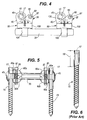
- One such headless pedicle screw is the screw associated with TSRH-3DTM manufactured by Medtronic Sofamor Danek. More particularly, the present invention is capable of working in conjunction with "bolt 88" disclosed in U.S. Pat. Nos. 5,643,263 and 5,885,285 to Simonson . The present invention is a replacement for the clamp found in U.S. Pat. Nos. 5,643,263 and 5,885,285 to Simonson . Details of the TSRH spinal implant system are disclosed in the " Surgical Technique Manual" provided by Danek Medical, Inc., published in 1990 .
- fixation devices for the treatment of vertebrae deformities and injuries is well known in the art.
- Various fixation devices are used in medical treatment to correct curvatures and deformities, treat trauma and remedy various abnormal spinal conditions. Treatment of these conditions generally requires the implantation of various component pieces such as support rods, crosslinks, caudal facing hooks, cranial facing hooks and like components, which form a spinal implant system.
- Bone screws are commonly used for anchoring spinal implant systems.
- the exact final position of a bone screw is difficult, if not impossible, to predict prior to the exposure of the patient's bone. This unpredictability results from the uncertainty of exact bone formation and shape within an individual patient. Additionally, it can be difficult to predetermine the structure of the bone, i.e. whether the bone is soft or even osteoporotic. Even if the final position of the screw can be predetermined, the necessary shape and position of a spinal rod implant may create unwanted stress upon the bone screw or the bone itself.
- Increased complexity of the installation procedure is undesirable because it increases a patient's time in surgery. Increased operating time is known to increase the risk of many complications associated with surgery. The additional time necessary to remove, or even temporarily dislocate, bone or muscular tissue also increases operating time, and thus the risk of complications.
- US-A-5 997 539 discloses a polyaxial orthopedic device for use with rod implant apparatus including a screw having a curvate ball top, a polyaxial head member having a socket into which the head of the screw is initially polyaxially nested, a vertical slot which renders the socket compressible, and a horizontal through hole having a tapered portion on one side of the vertical slot.
- a rod gripping cross-bar member, which is mounted through the through hole includes an axial split which permits the first end thereof to grip a rod, and then to be clamped onto the rod when the axial slot is narrowed.
- US-A-5 746 741 discloses an external fixator system comprising a clamp adapted to couple a fixator pin to a connecting rod.
- the clamp includes a slot for transversely receiving the body of the connecting rod.
- the slot preferably includes a region of reduced width, providing interference between the clamp and the connecting rod as it is inserted. This causes the clamp to snap onto the rod.
- a bolt is inserted through a hole passing through both sides of the slot.
- the bolt includes a head at one end formed in the shape of a hook adapted to hook the shaft of a fixator pin, and a thread at the opposite end.
- the bolt is rotatably mountable in the hole such that the fixator pin can be retained at a range of angles relative to the connecting rod.
- the clamp is attachable to a fixator pin and a connecting bar between two previously-installed clamps without disassembly of the system.
- a connector for securing two rods.
- the connector comprises a body including a first substantially conical surface having a slit and opposing joining sections adjacent the slit.
- the connector includes first and second receptacles for receiving first and second rods, respectively.
- the connector also includes a second substantially conical surface that is operatively associated with the first substantially conical surface.
- the connector includes means for urging the joining sections toward each other. Tension force is created within the connector upon urging the opposing joining sections in closer proximity because narrowing the slit reduces the diameter of the first substantially conical surface, which in turn pushes down on the second substantially conical surface.
- the tension force causes the two rods to be secured within the connector's receptacles because the receptacles create constricting or compressive forces around the rods.
- one rod may take the form of a shaft of a pedicle screw, while the other rod is a stabilization rod that bridges a problematic spinal disc.
- the connector may be of unitary or one-piece construction, or it may be formed of a plurality of parts, such as two-part construction.
- the receptacles are formed of bands that are interconnected.
- a two-member connector for securing two rods.
- the connector includes a first member having a first receptacle for one of the rods, a first substantially conical surface having a slit and opposing joining sections adjacent the slit.
- the connector also has a second member that includes a second receptacle for a second rod, and a second conical surface for contacting the first conical surface.
- the connector includes means for forcing the joining sections toward each other, wherein the two rods are secured within the connector upon forcing the joining sections toward each other.
- a connector for securing two rods includes a first member having an interior substantially conical surface having a slit and adjacent opposing joining sections.
- the first member also has a first rod band at least partially disposed through a center opening in the first member.
- the connector has a second member including an exterior substantially conical surface and a second rod band that is also at least partially disposed through a central opening in the second member.
- Means for interconnecting the first rod band to the second rod band are provided, such as by threading the two bands together.
- means for forcing the opposing joining sections toward each other are also provided, such as by using a threaded tightening screw.
- an end connector that utilizes an end position on the end of a rod to form at least a portion of the connector of the present invention.
- the end connector includes two substantially conical surface members where one of the conical surfaces is formed as an integral part of the end of the rod.
- this aspect of the invention allows for further controlling the eccentricity of the connector, as well as reducing the size of the connector because a second receptacle or rod band is not necessary given that the rod is already connected to the end connector.
- the end connector functions in a manner similar to the other connectors described herein.
- a slit along the first substantially conical surface is narrowed by using a tightening screw to pull the two opposing joining sections of the slit toward each other. This ultimately results in creating a compression force around the rod band that holds the pedicle screw, thereby securing the pedicle screw to the rod.
- a connector in yet a separate aspect of the invention, includes a plurality of pieces, and more particularly, a connector having four pieces is described.
- the four- piece connector includes first and second rod receiving members, and first and second substantially conical surface members.
- One of the conical surface members includes a slit and opposing joining sections adjacent the slit.
- Means for urging the joining sections toward each other is also provided, such as a tightening screw.
- the rod receiving members force the rods inserted therein to impinge upon the conical surface members, thereby securing the rods within the connector.
- a projection or surface texturing may be provided within a receptacle or rod band of the connector, and also potentially provided on the shaft of the screw or the rod to provide additional stability to the assembly.
- the minimal size of the connector device allows attachment of the device to human bone without significant displacement of human tissue. Therefore, the complexity of surgery and the following pain and discomfort of the patient may be minimized.
- the nature of the device, combined with its small size and profile, may allow a surgeon to attach the securement device to a secure portion of the human body without the need to remove bony processes which may be necessary to accommodate a larger attachment device.
- the simplicity of the elements, and the assembly process thereof reduces the training and experience or surgeons necessary to achieve desired results, and, may reduce the patient's time in surgery, thus reducing the risk and probability of surgical complications.
- a number of embodiments of the present invention may be used in combination to allow a surgeon great latitude in the selection of materials used.
- the surgeon may select from different embodiments of the connector to best fit the surgical implant parameters. With these choices, the surgeon may then best determine which embodiments of which elements to select to minimize removal or displacement of bodily tissue or bone, and thereby reduce both the patient's risk of surgical complications and post-surgical pain and discomfort.
- a significant feature of the present invention is the ability to provide a construct used to stabilize the spine or a portion thereof. This is a very low profile configuration (as compared to existing devices) that minimizes the length of the incision that is necessary to perform the surgery. Furthermore, a mechanical advantage is gained by the interaction of the components as previously described. Specifically, strength of the final connection is not simply attributable to the tightening of the tightening screw, but is also attributable, in part, to the placement of the spinal rod or screw shaft within the receptacles of the connector, and the wedge like interaction of the conical surfaces of the connector.
- the connector 10 includes a first rod band 45 and a second rod band 105.
- the connector includes substantially conical surfaces within the interior of the connector.
- the connector includes a slit and a means for drawing together the adjacent joining sections of the slit, thereby decreasing the diameter of the upper conical surface that in turn forces the lower conical surface downwards, thereby tightening the bands 45 and 105.
- the bands maybe tightened around two rods, such as a vertebrae stabilizing rod and the shank of a pedicle screw.
- a first embodiment of the connector 10 of the present invention is shown, wherein the connector is formed of two pieces.
- the present invention may be of unitary construction, or it may be constructed of a plurality of pieces, such as three or four pieces, as will be discussed below.
- connector 10 utilizes two-piece construction, wherein the first piece is first member 35.
- First member 35 shown in Figs. 2A-2D includes a first body 40, first rod band 45, first band fitting 50, slit 55, opposing joining sections 60a and 60b, openings 65a and 65b, interior substantially conical surface 70, and center body opening 75.
- First body 40 is preferably circular, although its exterior surface may be other shapes, such as square, rectangular, or a multi-side polyhedron.
- One end of first rod band 45 is connected to first body 40.
- First rod band 45 forms a loop along its length, thereby creating an opening or a first rod position 80. As first rod band 45 curves, it is disposed through center body opening 75 and extends below interior substantially conical surface 70.
- First band fitting 50 is preferably an interconnection device that allows first member 35 to be interconnected to the second piece of connector 10, as will be discussed below.
- First band fitting 50 includes interconnection means, such as threads, a hook, or a socket, that receives, or is received in, the second piece of connector 10.
- Joining sections 60a and 60b are adapted to provide means for pulling joining section 60a toward joining section 60b.
- joining sections 60a and 60b include openings 65a and 65b, respectively, that receivingly accept a tightening screw 85.
- tightening screw 85 is placed through openings 65a and 65b and is tightened to bring joining section 60a closer to joining section 60b. More particularly, due to the presence of slit 55 in first body 40 between joining sections 60a and 60b, tightening screw 85 is used to pull joining section 60a toward joining section 60b.
- Second member 90 includes a second body 100, second rod band 105, second rod band fitting 110, exterior substantially conical surface 115, and second central body opening 120.
- Second body 100 is preferably circular, although its exterior surface may be other shapes, such as square, rectangular, or a multi-side polyhedron, as long as the upper exterior surface is substantially conical, that is, exterior substantially conical surface 115.
- One end of second rod band 105 is interconnected to body 100.
- Second rod band 105 forms a loop along its length, thereby creating an opening or a second rod position 125. As second rod band 105 curves, it is disposed through or in the vicinity of center body opening 120.
- second member 90 may also be reduced, and therefore optimized, by reducing the size of its various components.
- the height of dimension "d 2 " of second body 100 may be adjusted to reduce the overall size of second member 90. Rounded corners may be incorporated into second body 100 to further reduce its size.
- exterior substantially conical surface 115 may be reduced in size by reducing its height "d 3 " depending upon the specific application.
- a separate aspect of the present invention is the ability to optimize the dimensions of the connector's components, by considering the specific application at hand. Optimization techniques are applied, such as finite element analysis, to calculate the anticipated stress and strain on the various structures of the connector. Thereafter, the size of the connector can be reduced to provide the minimum profile necessary to withstand the anticipated stresses, while still maintaining a satisfactory factor of safety against structural failure for the given mode of use.
- projections or surface texturing 130 may be added to a portion of the interior surface of first rod band 45.
- projections or surface texturing 130 may be added to a portion of the interior surface of second rod band 105.
- surface texturing may take the form of ridges and grooves or arcuate shaped projections. Such a configuration of texturing allows first rod band 45 and second rod band 105 to tighten around rods 20 or screws 15 held within their respective interior regions, namely first rod position 80 and second rod position 125.
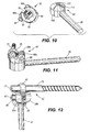
- Second rod receiving member 230 includes a second interlocking portion 235 and a second rod receiving portion 240.
- Second interlocking portion 235 is preferably circular in cross section, and includes female threads 245 that interlock with male threads 220 of first rod receiving member 205.
- Second rod receiving portion 240 is preferably rectangular or square in cross section, and includes second rod opening 250. Second rod opening 250 is sized to receive a rod 20 or the smooth shaft 19 of a pedicle screw 15.
- First rod opening 225 and second rod opening 250 are depicted in the figures to be circular; however, within this embodiment, rods of alternate shapes may be used, such as multiple-sided rods (not shown), or semicircular shafts that also have one flat side (also not shown).
- first interlocking portion 210 of first rod receiving member 205 passes through first circular opening 270 when connector 200 is assembled.
- flange 280 of recess 275 prevents first rod receiving portion 215 of first rod receiving member 205 from passing through first central opening 260. Rather, flange 280 of recess 275 retains first rod receiving portion 215 of first rod receiving member 205.
- optional grooves 265a, 265b serve to cradle rod 20 when it is inserted into first rod opening 225 of first rod receiving member 205.
- joining sections 60a and 60b include openings 65a and 65b, respectively, that receivingly accept a tightening screw 85.
- First conical surface member 255 also includes an interior substantially conical surface 285 located on the underside of first conical surface member 255, or situated on the surface of first conical surface member 255 opposite the location of grooves 265a, 265b. Interior substantially conical surface 285 of first conical surface member 255 contacts the second conical surface member 290, as described below.
- flange 320 of recess 315 retains second rod receiving portion 240 of second rod receiving member 230.
- optional grooves 305a, 305b serve to cradle rod 20 when it is inserted into second rod opening 250 of second rod receiving member 230.
- Connector 200 is assembled by passing first rod receiving member 205 through first conical surface member 255, and by passing second rod receiving member 230 through second conical surface member 290, and subsequently interconnecting male threads 220 of first rod receiving member 205 with female threads 245 of second rod receiving member 230.
- First conical surface member 255 is aligned with second conical surface member 290 such that interior substantially conical surface 285 of first conical surface member 255 contacts exterior substantially conical surface 295 of second conical surface member 290.
- a rod 20 or pedicle screw 15 is passed through first rod opening 225 of first rod receiving member 205, and through second rod opening 250 of second rod receiving member 230.
- Tightening screw 85 is then placed within openings 65a, 65b of joining sections 60a, 60b and is tightened.
- the action of advancing tightening screw 85 forces together joining section 60a with joining section 60b of first conical surface member 255.
- the movement of advancing joining section 60a toward joining section 60b reduces the diameter of interior substantially conical surface 285. This reduction in diameter progressively forces exterior substantially conical surface 295, and therefore, second conical surface member 290, to shift relative to interior substantially conical surface 285 of first conical surface member 255.
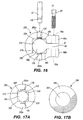
- Fig. 16 and 17A in a separate aspect of the invention, surface texturing 130 may be added to a portion of optional grooves 265a and/or 265b. Similarly, as shown in Fig. 8a, surface texturing 130 may be added to a portion of optional grooves 305a and/or 305b.
- surface texturing may take the form of ridges and grooves, with the ridges and valleys of the grooves preferably aligned perpendicular to the longitudinal axis of grooves 265a, 265b or 305a, 305b.
- the ridges and grooves of texturing 130 are preferably positioned to provide a mating surface with the exterior surface of a rod 20 or screw 15, which may also have texturing 130, and which is placed in contact with grooves 265a, 265b and/or 305a, 305b.
- Surface texturing 130 therefore, would tend to aid in preventing longitudinal motion of a rod 20 or screw 15 after connector 200 is tightened using tightening screw 85.
- Surface texturing 130 is considered optional, and is not necessary for the proper functioning of connector 200.
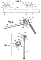
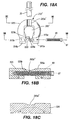
- a connector may be configured such that tightening screw 85 is aligned perpendicular to ipsilateral rod 20. More particularly, Fig. 18A depicts a top view of first conical surface member 255'. However, unlike first conical surface member 255 of connector 200, first conical surface member 255' is configured such that the longitudinal axis of tightening screw 85 is perpendicular to rod 20.
- First conical surface member 255' includes a first body 505, a first central opening 260', body joining sections 510a, 510b, section openings 515a, 515b, slit 520, and grooves 265a' and 265b'.
- First central opening 260' receivingly accepts first rod receiving member 205, in a manner similar to that previously described for connector 200.
- Tightening screw 85 is inserted into section openings 515a and 515b.
- body joining section 510a is drawn toward body section 510b.
- the interaction of the conical surfaces tighten and secure the connector in a manner similar to that described above.
- groove 265b' is formed by cradle wings 525a and 525b when body joining sections 510a and 510b are drawn toward each other.
- a conical surface can essentially be formed by a discontinuous ridge pattern, taking the analogous form of the ribs of an umbrella or an inverted umbrella, with or without a recessed surface between the ribs.
- spherical surfaces or spherical-like surfaces may be used within the connector.
- the conical surfaces noted herein may be substituted with surfaces similar to that of a ball.
- the conical surfaces noted herein may be substituted with undulating surfaces similar to that of a golf ball, with the individual dimpled surfaces projected outward, inward, or both.
- different size openings may preferably be used in the head opening 17 of pedicle screw 15 and the head opening 87 of tightening screw 85. More particularly, the use of different size or shaped openings in head openings 17 of pedicle screws 15 as compared to head openings 87 in tightening screws 85 may aid in preventing confusion during surgery. That is, head openings 87 of tightening screws 85 that require a different tool to tighten than the pedicle screw 15 may assist the surgeon in not over-tightening one screw when he or she believes they are tightening the other.
- Devices disclosed herein can also be made of thermal memory materials or materials that possess different elastic properties at varying temperatures.
- the subject component(s) may be heated or cooled to a desired temperature, implanted, then subsequently allowed to cool or warm to the temperature of the ambient conditions that will exist during the usage period for the subject device, namely, normal body temperature.
- the present invention has application to medical devices other than spinal implants.
- the present invention can be used in external fixator systems.
- connectors are used to secure rods to screws that project outside of the skin surface.
- the present invention offers a low-profile system of connecting two rods, or a rod to the shaft of a screw.
- the present invention may be used to secure various orthodontic appliances.
- it may be used to secure arch wires to brackets.
- it may be used in various orthodontic headgear apparatus.
- the present invention has application outside the medical field.
- the securing mechanism of the present invention is not limited to medical implants.
- the present invention could be used to secure any two wires, screws, rods, or a combination of these such devices, such as in linking mechanisms, and has application to any type of mechanical device with static or moving parts.
- Other applications by no means exhaustive, may include connecting legs of a tripod to a base and mounting track lighting fixtures.
Landscapes
- Health & Medical Sciences (AREA)
- Orthopedic Medicine & Surgery (AREA)
- Life Sciences & Earth Sciences (AREA)
- Neurology (AREA)
- Surgery (AREA)
- Heart & Thoracic Surgery (AREA)
- Engineering & Computer Science (AREA)
- Biomedical Technology (AREA)
- Nuclear Medicine, Radiotherapy & Molecular Imaging (AREA)
- Medical Informatics (AREA)
- Molecular Biology (AREA)
- Animal Behavior & Ethology (AREA)
- General Health & Medical Sciences (AREA)
- Public Health (AREA)
- Veterinary Medicine (AREA)
- Surgical Instruments (AREA)
- Joining Of Building Structures In Genera (AREA)
- Dowels (AREA)
Claims (13)
- Verbindungsmittel (10; 10'), um zwei Stäbe (15, 20) aneinander zu befestigen, umfassend:- eine erste im Wesentlichen konische Fläche (70);- eine zweite im Wesentlichen konische Fläche (115), die betrieblich mit der ersten im Wesentlichen konischen Fläche (70) verbunden ist;- eine erste Aufnahme (45), um einen ersten (15) der beiden Stäbe (15, 20) aufzunehmen; und- - eine zweite Aufnahme (105), um einen zweiten (20) der beiden Stäbe (15, 20) aufzunehmen;
dadurch gekennzeichnet, dass- die erste Aufnahme aus einem Stabband (45) besteht; und- die erste im Wesentlichen konische Fläche (70) Folgendes aufweist: einen Schlitz (55), der einander gegenüberliegende Verbindungsabschnitte (60a, 60b) der Fläche trennt, und ein Mittel (85), um die einander gegenüberliegenden Verbindungsabschnitte (60a, 60b) zueinander zu drängen, wodurch verursacht wird, dass das erste Stabband (45) um den ersten Stab (15) festgezogen wird, um den zweiten Stab (20) und den ersten Stab (15) aneinander zu sperren. - Verbindungsmittel (10; 10') nach Anspruch 1, wobei das Verbindungsmittel (10') aus einem einstückigen Aufbau besteht.
- Verbindungsmittel (10; 10') nach Anspruch 2, wobei das Verbindungsmittel (10) aus einem zweiteiligen Aufbau (35, 90; 90') besteht.
- Verbindungsmittel (10') nach Anspruch 1, wobei der zweite Stab (20) einstückig mit der zweiten im Wesentlichen konischen Fläche (115) verbunden ist.
- Verbindungsmittel (10; 10') nach Anspruch 1, wobei das Mittel zum Drängen eine Spannschraube umfasst.
- Verbindungsmittel (10) nach Anspruch 1, wobei die zweite Aufnahme ein Stabband (105) umfasst.
- Verbindungsmittel (10; 10') nach Anspruch 1, wobei das erste Stabband (45) eine erste Stabbandverschraubung (50) umfasst.
- Verbindungsmittel (10; 10') nach Anspruch 6, wobei das zweite Stabband (105) eine zweite Stabbandverschraubung (110) umfasst.
- Verbindungsmittel (10; 10') nach Anspruch 1, wobei das erste Stabband (45) dazu geeignet ist, einen Schaft (19) einer Pedikelschraube (15) aufzunehmen.
- Verbindungsmittel (10; 10') nach Anspruch 6, wobei das zweite Stabband (105) dazu geeignet ist, einen Wirbelsäulen-Stabilisierungsstab (20) aufzunehmen.
- Verbindungsmittel (10; 10') nach Anspruch 6, wobei das erste Stabband (45) an das zweite Stabband (105) geschraubt ist.
- Verbindungsmittel (10; 10') nach Anspruch 1, wobei das erste Stabband (45) ferner eine Oberflächentexturierung umfasst.
- Verbindungsmittel (10; 10') nach Anspruch 6, wobei das zweite Stiftbans (105) ferner eine Oberflächentexturierung umfasst.
Applications Claiming Priority (3)
| Application Number | Priority Date | Filing Date | Title |
|---|---|---|---|
| US35924602P | 2002-02-20 | 2002-02-20 | |
| US359246P | 2002-02-20 | ||
| PCT/US2003/005086 WO2003073908A2 (en) | 2002-02-20 | 2003-02-20 | Pedicle screw connector apparatus and method |
Publications (3)
| Publication Number | Publication Date |
|---|---|
| EP1545353A2 EP1545353A2 (de) | 2005-06-29 |
| EP1545353A4 EP1545353A4 (de) | 2009-06-24 |
| EP1545353B1 true EP1545353B1 (de) | 2010-08-11 |
Family
ID=27788961
Family Applications (1)
| Application Number | Title | Priority Date | Filing Date |
|---|---|---|---|
| EP03733832A Expired - Lifetime EP1545353B1 (de) | 2002-02-20 | 2003-02-20 | Gerät zur verbindung von stielschrauben |
Country Status (8)
| Country | Link |
|---|---|
| US (2) | US7763047B2 (de) |
| EP (1) | EP1545353B1 (de) |
| JP (1) | JP4408703B2 (de) |
| AT (1) | ATE476930T1 (de) |
| AU (1) | AU2003239118B2 (de) |
| CA (1) | CA2475200C (de) |
| DE (1) | DE60333764D1 (de) |
| WO (1) | WO2003073908A2 (de) |
Families Citing this family (61)
| Publication number | Priority date | Publication date | Assignee | Title |
|---|---|---|---|---|
| US6736816B2 (en) | 2000-06-30 | 2004-05-18 | Stephen Ritland | Polyaxial connection device and method |
| US7166073B2 (en) | 2000-09-29 | 2007-01-23 | Stephen Ritland | Method and device for microsurgical intermuscular spinal surgery |
| US6692434B2 (en) | 2000-09-29 | 2004-02-17 | Stephen Ritland | Method and device for retractor for microsurgical intermuscular lumbar arthrodesis |
| US8021399B2 (en) | 2005-07-19 | 2011-09-20 | Stephen Ritland | Rod extension for extending fusion construct |
| ATE495709T1 (de) | 2001-09-28 | 2011-02-15 | Stephen Ritland | Verbindungsstange für ein polyaxiales system mit schraube oder haken |
| ATE476930T1 (de) | 2002-02-20 | 2010-08-15 | Stephen Ritland | Gerät zur verbindung von stielschrauben |
| US6966910B2 (en) | 2002-04-05 | 2005-11-22 | Stephen Ritland | Dynamic fixation device and method of use |
| WO2003094699A2 (en) | 2002-05-08 | 2003-11-20 | Stephen Ritland | Dynamic fixation device and method of use |
| EP1596738A4 (de) | 2003-02-25 | 2010-01-20 | Stephen Ritland | Verstellbare stangen- und verbindungsvorrichtung und anwendungsverfahren |
| WO2004110247A2 (en) | 2003-05-22 | 2004-12-23 | Stephen Ritland | Intermuscular guide for retractor insertion and method of use |
| US7678137B2 (en) | 2004-01-13 | 2010-03-16 | Life Spine, Inc. | Pedicle screw constructs for spine fixation systems |
| US7909852B2 (en) * | 2004-03-31 | 2011-03-22 | Depuy Spine Sarl | Adjustable-angle spinal fixation element |
| US7938848B2 (en) | 2004-06-09 | 2011-05-10 | Life Spine, Inc. | Spinal fixation system |
| US8021398B2 (en) | 2004-06-09 | 2011-09-20 | Life Spine, Inc. | Spinal fixation system |
| US7744635B2 (en) | 2004-06-09 | 2010-06-29 | Spinal Generations, Llc | Spinal fixation system |
| US7959653B2 (en) | 2004-09-03 | 2011-06-14 | Lanx, Inc. | Spinal rod cross connector |
| US7455639B2 (en) | 2004-09-20 | 2008-11-25 | Stephen Ritland | Opposing parallel bladed retractor and method of use |
| US20060085076A1 (en) | 2004-10-15 | 2006-04-20 | Manoj Krishna | Posterior spinal arthroplasty-development of a new posteriorly inserted artificial disc and an artificial facet joint |
| US20070225713A1 (en) * | 2004-10-20 | 2007-09-27 | Moti Altarac | Systems and methods for posterior dynamic stabilization of the spine |
| EP1814474B1 (de) | 2004-11-24 | 2011-09-14 | Samy Abdou | Vorrichtungen zur platzierung eines orthopädischen intervertebralen implantats |
| WO2007081986A2 (en) | 2006-01-10 | 2007-07-19 | Life Spine, Inc. | Pedicle screw constructs and spinal rod attachment assemblies |
| CA2648204C (en) | 2006-04-11 | 2014-07-22 | Synthes (U.S.A.) | Minimally invasive fixation system |
| US7789897B2 (en) * | 2006-04-11 | 2010-09-07 | Warsaw Orthopedic, Inc. | Pedicle screw spinal rod connector arrangement |
| US7959564B2 (en) | 2006-07-08 | 2011-06-14 | Stephen Ritland | Pedicle seeker and retractor, and methods of use |
| US8388660B1 (en) | 2006-08-01 | 2013-03-05 | Samy Abdou | Devices and methods for superior fixation of orthopedic devices onto the vertebral column |
| US9867640B2 (en) | 2006-12-07 | 2018-01-16 | Nexus Spine, LLC | Press-on pedicle screw assembly |
| US8308801B2 (en) * | 2007-02-12 | 2012-11-13 | Brigham Young University | Spinal implant |
| CN101754724B (zh) * | 2007-07-19 | 2012-04-18 | 新特斯有限责任公司 | 用于将骨锚互连到杆上的夹具 |
| CA2743721A1 (en) | 2009-02-19 | 2010-08-26 | Anton E. Bowden | Compliant dynamic spinal implant |
| WO2010096829A2 (en) | 2009-02-23 | 2010-08-26 | Crocker Spinal, L.L.C. | Press-on link for surgical screws |
| US8998961B1 (en) | 2009-02-26 | 2015-04-07 | Lanx, Inc. | Spinal rod connector and methods |
| US8091305B2 (en) * | 2009-02-27 | 2012-01-10 | Skeeter Jane A | Recycled glass structural and decorative barrier or building, lighting and furniture component |
| WO2010108010A2 (en) * | 2009-03-19 | 2010-09-23 | Halverson Peter A | Spinal implant |
| KR101767274B1 (ko) | 2009-05-20 | 2017-08-10 | 신세스 게엠바하 | 환자-장착 견인 장치 |
| US20110009906A1 (en) * | 2009-07-13 | 2011-01-13 | Zimmer Spine, Inc. | Vertebral stabilization transition connector |
| US8657856B2 (en) * | 2009-08-28 | 2014-02-25 | Pioneer Surgical Technology, Inc. | Size transition spinal rod |
| US9157497B1 (en) | 2009-10-30 | 2015-10-13 | Brigham Young University | Lamina emergent torsional joint and related methods |
| US8764806B2 (en) | 2009-12-07 | 2014-07-01 | Samy Abdou | Devices and methods for minimally invasive spinal stabilization and instrumentation |
| US9050138B2 (en) | 2010-01-28 | 2015-06-09 | Warsaw Orthopedic, Inc. | Vertebral rod connector and methods of use |
| US8535318B2 (en) | 2010-04-23 | 2013-09-17 | DePuy Synthes Products, LLC | Minimally invasive instrument set, devices and related methods |
| US9387013B1 (en) | 2011-03-01 | 2016-07-12 | Nuvasive, Inc. | Posterior cervical fixation system |
| EP2517660B1 (de) | 2011-04-25 | 2018-03-07 | Nexus Spine, L.L.C. | Kopplungssystem für ein chirurgisches Konstrukt |
| WO2012166495A1 (en) | 2011-05-27 | 2012-12-06 | Synthes Usa, Llc | Minimally invasive spinal fixation system including vertebral alignment features |
| EP2717807A2 (de) | 2011-06-07 | 2014-04-16 | Brigham Young University | Gewundene wirbelsäulenstabilitätsvorrichtung und zugehörige verfahren |
| US9005249B2 (en) | 2011-07-11 | 2015-04-14 | Life Spine, Inc. | Spinal rod connector assembly |
| US8845728B1 (en) | 2011-09-23 | 2014-09-30 | Samy Abdou | Spinal fixation devices and methods of use |
| US20130226240A1 (en) | 2012-02-22 | 2013-08-29 | Samy Abdou | Spinous process fixation devices and methods of use |
| WO2013177314A1 (en) * | 2012-05-22 | 2013-11-28 | The Regents Of The University Of California | A method and device for restabilization with axial rotation of the atlantoaxial junction |
| US9198767B2 (en) | 2012-08-28 | 2015-12-01 | Samy Abdou | Devices and methods for spinal stabilization and instrumentation |
| US9320617B2 (en) | 2012-10-22 | 2016-04-26 | Cogent Spine, LLC | Devices and methods for spinal stabilization and instrumentation |
| AU2013334732B2 (en) | 2012-10-23 | 2017-08-03 | Nexus Spine, L.L.C. | Surgical construct coupling system |
| CN105682583B (zh) * | 2013-09-01 | 2019-01-04 | 碳固定因骨科有限责任公司 | 复合材料脊椎植入物 |
| US20150250464A1 (en) | 2014-03-07 | 2015-09-10 | John Song | Spinal Compressor and Distractor |
| WO2015191884A1 (en) | 2014-06-12 | 2015-12-17 | Brigham Young University | Inverted serpentine spinal stability device and associated methods |
| US10857003B1 (en) | 2015-10-14 | 2020-12-08 | Samy Abdou | Devices and methods for vertebral stabilization |
| EP3413819B1 (de) | 2016-02-12 | 2022-07-06 | Nuvasive, Inc. | Postoperativ einstellbare abgewinkelte stange |
| US11446063B2 (en) | 2016-02-12 | 2022-09-20 | Nuvasive, Inc. | Post-operatively adjustable angled rod |
| US10973648B1 (en) | 2016-10-25 | 2021-04-13 | Samy Abdou | Devices and methods for vertebral bone realignment |
| US10744000B1 (en) | 2016-10-25 | 2020-08-18 | Samy Abdou | Devices and methods for vertebral bone realignment |
| US11179248B2 (en) | 2018-10-02 | 2021-11-23 | Samy Abdou | Devices and methods for spinal implantation |
| CN114788726B (zh) * | 2021-01-26 | 2025-02-07 | 仉建国 | 可调节生长阀及脊柱后路内固定系统 |
Family Cites Families (359)
| Publication number | Priority date | Publication date | Assignee | Title |
|---|---|---|---|---|
| US569839A (en) | 1896-10-20 | John t | ||
| US605652A (en) | 1898-06-14 | Endoscopic instrument | ||
| US2191A (en) | 1841-07-23 | Constructing the surgical instrument denominated the | ||
| US1090746A (en) | 1913-04-26 | 1914-03-17 | Frank P Nourse | Speculum. |
| US1097978A (en) | 1913-06-14 | 1914-05-26 | Hardwick Jackson J | Combined dilator and catheter. |
| US3470872A (en) | 1966-11-25 | 1969-10-07 | Herman R Grieshaber | Pivoted retractor with shielded spacer teeth |
| US3467079A (en) | 1967-04-14 | 1969-09-16 | David Charles James | Gall bladder and common duct retractor |
| SE7316352L (de) | 1973-12-04 | 1975-05-05 | ||
| US3875595A (en) | 1974-04-15 | 1975-04-08 | Edward C Froning | Intervertebral disc prosthesis and instruments for locating same |
| GB1551706A (en) | 1975-04-28 | 1979-08-30 | Downs Surgical Ltd | Surgical implant |
| US4232660A (en) | 1979-03-26 | 1980-11-11 | Coles Robert L | Winged irrigating surgical retractor |
| US4481947A (en) | 1980-02-14 | 1984-11-13 | Chester Martin H | Endotracheal tube retractor |
| US4440168A (en) | 1981-08-31 | 1984-04-03 | Warren Mark G | Surgical device |
| US4617922A (en) | 1982-01-18 | 1986-10-21 | Richards Medical Company | Compression screw assembly |
| US4545374A (en) | 1982-09-03 | 1985-10-08 | Jacobson Robert E | Method and instruments for performing a percutaneous lumbar diskectomy |
| US4573448A (en) | 1983-10-05 | 1986-03-04 | Pilling Co. | Method for decompressing herniated intervertebral discs |
| US4736738A (en) | 1984-07-09 | 1988-04-12 | Matej Lipovsek | Instrument kit and procedure for performing posterior lumbar interbody fusion |
| CH671873A5 (de) | 1985-10-03 | 1989-10-13 | Synthes Ag | |
| US4743260A (en) | 1985-06-10 | 1988-05-10 | Burton Charles V | Method for a flexible stabilization system for a vertebral column |
| US4620460A (en) | 1985-07-01 | 1986-11-04 | Gonzales Jr Frank | Socket set |
| DE3614101C1 (de) | 1986-04-25 | 1987-10-22 | Juergen Prof Dr Med Harms | Pedikelschraube |
| US4686972A (en) | 1986-04-30 | 1987-08-18 | Kurland Kenneth Z | Surgical deflector and drilling guide |
| US4747394A (en) | 1986-10-08 | 1988-05-31 | Watanabe Orthopedic Systems, Inc. | Spinal retractor |
| US4889112A (en) | 1987-01-23 | 1989-12-26 | Waltap Ltd. | Apparatus for performing a tracheostomy operation |
| US4798111A (en) | 1987-08-03 | 1989-01-17 | Cheeseman Charles D | Socket-wrench hand tool |
| US4817587A (en) | 1987-08-31 | 1989-04-04 | Janese Woodrow W | Ring para-spinal retractor |
| GB2209673B (en) | 1987-09-15 | 1991-06-12 | Wallace Ltd H G | Catheter and cannula assembly |
| DE3736066C1 (de) | 1987-10-24 | 1988-11-10 | Aesculap Werke Ag | Wundhaken |
| US4862891A (en) | 1988-03-14 | 1989-09-05 | Canyon Medical Products | Device for sequential percutaneous dilation |
| US4995875A (en) | 1988-05-27 | 1991-02-26 | Cecil Coes | Femoral elevating tool |
| DE8807485U1 (de) | 1988-06-06 | 1989-08-10 | Mecron Medizinische Produkte Gmbh, 1000 Berlin | Endoprothese der Zwischenwirbelscheibe |
| US6123705A (en) | 1988-06-13 | 2000-09-26 | Sdgi Holdings, Inc. | Interbody spinal fusion implants |
| EP0703757B1 (de) | 1988-06-13 | 2003-08-27 | Karlin Technology, Inc. | Gerät zum einsetzen von rückenwirbelimplantaten |
| US5593409A (en) | 1988-06-13 | 1997-01-14 | Sofamor Danek Group, Inc. | Interbody spinal fusion implants |
| US5052373A (en) | 1988-07-29 | 1991-10-01 | Michelson Gary K | Spinal retractor |
| US4961740B1 (en) | 1988-10-17 | 1997-01-14 | Surgical Dynamics Inc | V-thread fusion cage and method of fusing a bone joint |
| US4882958A (en) | 1988-12-05 | 1989-11-28 | Mcneeley Richard L | Stacking socket wrench set |
| US5024213A (en) | 1989-02-08 | 1991-06-18 | Acromed Corporation | Connector for a corrective device |
| DE3918431C1 (de) | 1989-06-06 | 1990-07-26 | B. Braun Melsungen Ag, 3508 Melsungen, De | |
| US5048379A (en) | 1989-06-16 | 1991-09-17 | Gramera Robert E | Multi-functional double-ended socket wrenches |
| US5030223A (en) | 1989-06-30 | 1991-07-09 | Iowa State University Research Foundation, Inc. | Head mounted stereotaxic apparatus |
| US5458638A (en) | 1989-07-06 | 1995-10-17 | Spine-Tech, Inc. | Non-threaded spinal implant |
| DE3922406C1 (de) | 1989-07-07 | 1990-10-11 | B. Braun Melsungen Ag, 3508 Melsungen, De | |
| US5002542A (en) | 1989-10-30 | 1991-03-26 | Synthes U.S.A. | Pedicle screw clamp |
| US5055104A (en) | 1989-11-06 | 1991-10-08 | Surgical Dynamics, Inc. | Surgically implanting threaded fusion cages between adjacent low-back vertebrae by an anterior approach |
| US5084043A (en) | 1990-01-12 | 1992-01-28 | Laserscope | Method for performing a percutaneous diskectomy using a laser |
| US5018507A (en) | 1990-01-26 | 1991-05-28 | Montaldi David H | One-piece disposable speculum |
| US5030220A (en) | 1990-03-29 | 1991-07-09 | Advanced Spine Fixation Systems Incorporated | Spine fixation system |
| US5360431A (en) | 1990-04-26 | 1994-11-01 | Cross Medical Products | Transpedicular screw system and method of use |
| DE9004960U1 (de) | 1990-05-02 | 1991-08-29 | Pfeil, Joachim, Dr.Med. | Halo-Fixateur zur Behandlung von Halswirbelsäulenerkrankungen und -verletzungen |
| US5133720A (en) | 1990-07-13 | 1992-07-28 | Greenberg Alex M | Surgical drill guide and retractor |
| US5129900B1 (en) | 1990-07-24 | 1998-12-29 | Acromed Corp | Spinal column retaining method and apparatus |
| US6224608B1 (en) | 1990-08-10 | 2001-05-01 | United States Surgical Corporation | Tissue holding device and method |
| FR2666981B1 (fr) | 1990-09-21 | 1993-06-25 | Commarmond Jacques | Ligament synthetique vertebral. |
| US5165306A (en) | 1990-10-04 | 1992-11-24 | Maclean-Fogg Company | Vehicle stabilizer bar end link |
| US5158543A (en) | 1990-10-30 | 1992-10-27 | Lazarus Harrison M | Laparoscopic surgical system and method |
| EP0558642B1 (de) | 1990-11-20 | 1997-01-02 | InnerDyne, Inc. | Dehnung aufrechterhaltendes führungselement sowie dilatator |
| US5098435A (en) | 1990-11-21 | 1992-03-24 | Alphatec Manufacturing Inc. | Cannula |
| FR2672202B1 (fr) | 1991-02-05 | 1993-07-30 | Safir | Implant chirurgical osseux, notamment pour stabilisateur inter-vertebral. |
| US5129899A (en) | 1991-03-27 | 1992-07-14 | Smith & Nephew Richards Inc. | Bone fixation apparatus |
| US5217007A (en) | 1991-04-26 | 1993-06-08 | Cook Incorporated | Speculum for forming an ostomy in a trachea |
| GB9110778D0 (en) | 1991-05-18 | 1991-07-10 | Middleton Jeffrey K | Apparatus for use in surgery |
| US5148724A (en) | 1991-06-13 | 1992-09-22 | Rexford Gary R | Ratchet wrench and socket apparatus |
| US5269797A (en) | 1991-09-12 | 1993-12-14 | Meditron Devices, Inc. | Cervical discectomy instruments |
| US5330474A (en) | 1991-09-23 | 1994-07-19 | Lin Chih I | Vertebral locking and retrieving system |
| US5489274A (en) | 1992-10-09 | 1996-02-06 | Boston Scientific Corporation | Rotatable medical valve closure |
| US5195541A (en) | 1991-10-18 | 1993-03-23 | Obenchain Theodore G | Method of performing laparoscopic lumbar discectomy |
| FR2683712B1 (fr) | 1991-11-18 | 1995-12-29 | Hades | Capuchon de protection d'une broche d'osteosynthese et ensemble comportant ce capuchon ainsi qu'un organe pour sa fixation sur la broche. |
| US5766221A (en) | 1991-12-03 | 1998-06-16 | Boston Scientific Technology, Inc. | Bone anchor implantation device |
| DE9202745U1 (de) | 1992-03-02 | 1992-04-30 | Howmedica Gmbh, 2314 Schoenkirchen | Vorrichtung zum Verspannen von Wirbeln der menschlichen Wirbelsäule |
| US5306309A (en) | 1992-05-04 | 1994-04-26 | Calcitek, Inc. | Spinal disk implant and implantation kit |
| FR2691069B1 (fr) | 1992-05-14 | 1999-08-20 | Vygon | Instrument chirurgical pour operation d'anesthesie peridurale. |
| US5250055A (en) | 1992-06-08 | 1993-10-05 | Orthopedic Systems Inc. | Method and apparatus for tying suture to bone |
| US5810817A (en) * | 1992-06-19 | 1998-09-22 | Roussouly; Pierre | Spinal therapy apparatus |
| EP0599847B1 (de) * | 1992-06-25 | 1997-04-02 | Synthes AG, Chur | Osteosynthetische fixationsvorrichtung |
| US5279567A (en) | 1992-07-02 | 1994-01-18 | Conmed Corporation | Trocar and tube with pressure signal |
| US5312405A (en) | 1992-07-06 | 1994-05-17 | Zimmer, Inc. | Spinal rod coupler |
| US5275600A (en) | 1992-10-05 | 1994-01-04 | Zimmer, Inc. | Telescoping rod to rod coupler for a spinal system |
| ZA937672B (en) | 1992-10-22 | 1994-05-16 | Danek Medical Inc | Spinal rod transverse connector for supporting vertebral fixation elements |
| US5484440A (en) | 1992-11-03 | 1996-01-16 | Zimmer, Inc. | Bone screw and screwdriver |
| CA2109907C (en) | 1992-11-25 | 2000-01-25 | Ronald A. Yapp | Osteosynthesis plate system |
| US5498262A (en) * | 1992-12-31 | 1996-03-12 | Bryan; Donald W. | Spinal fixation apparatus and method |
| US5947965A (en) * | 1992-12-31 | 1999-09-07 | Bryan; Donald W. | Spinal fixation apparatus and method |
| US5306275A (en) * | 1992-12-31 | 1994-04-26 | Bryan Donald W | Lumbar spine fixation apparatus and method |
| US5292309A (en) | 1993-01-22 | 1994-03-08 | Schneider (Usa) Inc. | Surgical depth measuring instrument and method |
| US5431651A (en) | 1993-02-08 | 1995-07-11 | Goble; E. Marlowe | Cross pin and set screw femoral and tibial fixation method |
| US5303694A (en) | 1993-02-09 | 1994-04-19 | Mikhail Michael W E | Method for performing hip surgery and retractor for use therein |
| FR2701650B1 (fr) | 1993-02-17 | 1995-05-24 | Psi | Amortisseur double pour la stabilisation intervertébrale. |
| US5330473A (en) * | 1993-03-04 | 1994-07-19 | Advanced Spine Fixation Systems, Inc. | Branch connector for spinal fixation systems |
| US5439464A (en) | 1993-03-09 | 1995-08-08 | Shapiro Partners Limited | Method and instruments for performing arthroscopic spinal surgery |
| US5356413A (en) | 1993-03-12 | 1994-10-18 | Mitek Surgical Products, Inc. | Surgical anchor and method for deploying the same |
| US5565502A (en) | 1993-03-24 | 1996-10-15 | Children's Medical Center Corporation | Isolation of the calcium-phosphate crystals of bone |
| US5415661A (en) | 1993-03-24 | 1995-05-16 | University Of Miami | Implantable spinal assist device |
| US5304179A (en) | 1993-06-17 | 1994-04-19 | Amei Technologies Inc. | System and method for installing a spinal fixation system at variable angles |
| US5363841A (en) | 1993-07-02 | 1994-11-15 | Coker Wesley L | Retractor for spinal surgery |
| US5584831A (en) | 1993-07-09 | 1996-12-17 | September 28, Inc. | Spinal fixation device and method |
| US5423816A (en) | 1993-07-29 | 1995-06-13 | Lin; Chih I. | Intervertebral locking device |
| FR2708461B1 (fr) | 1993-08-06 | 1995-09-29 | Advanced Technical Fabrication | Implant intersomatique pour colonne vertébrale. |
| US5431639A (en) | 1993-08-12 | 1995-07-11 | Boston Scientific Corporation | Treating wounds caused by medical procedures |
| US5466238A (en) | 1993-08-27 | 1995-11-14 | Lin; Chih-I | Vertebral locking and retrieving system having a fixation crossbar |
| CN1156255C (zh) | 1993-10-01 | 2004-07-07 | 美商-艾克罗米德公司 | 脊椎植入物 |
| WO1995010238A1 (en) | 1993-10-08 | 1995-04-20 | Chaim Rogozinski | Spinal treatment apparatus and method including multi-directional attachment member |
| US5512038A (en) | 1993-11-15 | 1996-04-30 | O'neal; Darrell D. | Spinal retractor apparatus having a curved blade |
| JPH07163580A (ja) | 1993-12-15 | 1995-06-27 | Mizuho Ika Kogyo Kk | 側弯症前方矯正装置 |
| US5628740A (en) | 1993-12-23 | 1997-05-13 | Mullane; Thomas S. | Articulating toggle bolt bone screw |
| US5499983A (en) * | 1994-02-23 | 1996-03-19 | Smith & Nephew Richards, Inc. | Variable angle spinal screw |
| USD361381S (en) | 1994-03-17 | 1995-08-15 | Tibor Koros | Combined spine and sternum retractor frame |
| FR2718944B1 (fr) * | 1994-04-20 | 1996-08-30 | Pierre Roussouly | Dispositif de stabilisation d'ancrage orthopédique. |
| FR2718945B1 (fr) * | 1994-04-25 | 1996-07-05 | Soprane Sa | Dispositif de retenue d'une tige de liaison d'un fixateur de rachis sur une vis pédiculaire. |
| ES2081766B1 (es) | 1994-05-13 | 1996-10-01 | Bilbao Ortiz De Zarate Jose Ra | Sistema de fijacion vertebral cervical por via posterior. |
| US6162236A (en) | 1994-07-11 | 2000-12-19 | Terumo Kabushiki Kaisha | Trocar needle and expandable trocar tube |
| US5545166A (en) | 1994-07-14 | 1996-08-13 | Advanced Spine Fixation Systems, Incorporated | Spinal segmental reduction derotational fixation system |
| FR2722980B1 (fr) | 1994-07-26 | 1996-09-27 | Samani Jacques | Implant vertebral inter-epineux |
| US5695993A (en) | 1994-08-12 | 1997-12-09 | Oklahoma Medical Research Foundation | Cloning and regulation of an endothelial cell protein C/activated protein C receptor |
| JP2802244B2 (ja) | 1994-08-29 | 1998-09-24 | オリンパス光学工業株式会社 | 内視鏡用シース |
| US5558622A (en) | 1994-09-02 | 1996-09-24 | Greenberg Surgical Technologies, Llc | Mandibular border retractor and method for fixating a fractured mandible |
| US5885299A (en) | 1994-09-15 | 1999-03-23 | Surgical Dynamics, Inc. | Apparatus and method for implant insertion |
| EP0781113B1 (de) | 1994-09-15 | 2002-03-27 | Surgical Dynamics, Inc. | Konischer fusionskäfig |
| US5601550A (en) | 1994-10-25 | 1997-02-11 | Esser; Rene D. | Pelvic pin guide system for insertion of pins into iliac bone |
| US6176861B1 (en) * | 1994-10-25 | 2001-01-23 | Sdgi Holdings, Inc. | Modular spinal system |
| US6004322A (en) * | 1994-10-25 | 1999-12-21 | Sdgi Holdings, Inc. | Modular pedicle screw system |
| US5683389A (en) | 1994-12-05 | 1997-11-04 | Smith & Nephew, Inc. | External fixator for distal radius fractures |
| WO1996018363A1 (en) | 1994-12-08 | 1996-06-20 | Vanderbilt University | Low profile intraosseous anterior spinal fusion system and method |
| DE59504219D1 (de) | 1995-02-17 | 1998-12-17 | Sulzer Orthopaedie Ag | Verbindungssystem für Pedikelschrauben |
| FR2731344B1 (fr) | 1995-03-06 | 1997-08-22 | Dimso Sa | Instrumentation rachidienne notamment pour tige |
| US5591235A (en) | 1995-03-15 | 1997-01-07 | Kuslich; Stephen D. | Spinal fixation device |
| US6245072B1 (en) | 1995-03-27 | 2001-06-12 | Sdgi Holdings, Inc. | Methods and instruments for interbody fusion |
| US5591166A (en) | 1995-03-27 | 1997-01-07 | Smith & Nephew Richards, Inc. | Multi angle bone bolt |
| US6206922B1 (en) | 1995-03-27 | 2001-03-27 | Sdgi Holdings, Inc. | Methods and instruments for interbody fusion |
| SE504379C2 (sv) * | 1995-04-10 | 1997-01-27 | Sven Olerud | Låsanordning för fixering av två korsande stavformiga implantat för lägesjustering av ryggkotor |
| US5716355A (en) * | 1995-04-10 | 1998-02-10 | Sofamor Danek Group, Inc. | Transverse connection for spinal rods |
| US5569300A (en) | 1995-04-12 | 1996-10-29 | Redmon; Henry A. | Dilating surgical forceps having illumination means on blade inner surface |
| US5613968A (en) | 1995-05-01 | 1997-03-25 | Lin; Chih-I | Universal pad fixation device for orthopedic surgery |
| US5630816A (en) | 1995-05-01 | 1997-05-20 | Kambin; Parviz | Double barrel spinal fixation system and method |
| US5562663A (en) | 1995-06-07 | 1996-10-08 | Danek Medical, Inc. | Implant interconnection mechanism |
| FR2735351B1 (fr) | 1995-06-13 | 1997-09-12 | Sofamor | Implant pour le traitement chirurgical d'une fracture isthmique vertebrale |
| US5643263A (en) * | 1995-08-14 | 1997-07-01 | Simonson; Peter Melott | Spinal implant connection assembly |
| US5645544A (en) | 1995-09-13 | 1997-07-08 | Danek Medical, Inc. | Variable angle extension rod |
| US5643264A (en) | 1995-09-13 | 1997-07-01 | Danek Medical, Inc. | Iliac screw |
| CA2158890C (en) | 1995-09-22 | 2002-01-22 | John Runciman | Spherical washer for use with a bone screw |
| US6273914B1 (en) * | 1995-09-28 | 2001-08-14 | Sparta, Inc. | Spinal implant |
| US5683392A (en) | 1995-10-17 | 1997-11-04 | Wright Medical Technology, Inc. | Multi-planar locking mechanism for bone fixation |
| US5746720A (en) | 1995-10-18 | 1998-05-05 | Stouder, Jr.; Albert E. | Method and apparatus for insertion of a cannula and trocar |
| US5882344A (en) | 1995-10-18 | 1999-03-16 | Stouder, Jr.; Albert E. | Adjustable length cannula and trocar |
| US5690632A (en) | 1995-11-30 | 1997-11-25 | Schwartz; Paul Steven | Osteosynthesis screw fastener having angularly adjustable threads and methods of use therefor |
| CA2191405C (en) * | 1995-12-01 | 2003-03-25 | David Walker | Telescopic bone plate for use in bone lengthening by distraction osteogenesis |
| US5687739A (en) | 1995-12-06 | 1997-11-18 | Interventional Concepts, Inc. | Biopsy specimen cutter |
| US6425901B1 (en) | 1995-12-07 | 2002-07-30 | Loma Linda University Medical Center | Vascular wound closure system |
| US5816257A (en) | 1995-12-20 | 1998-10-06 | Origin Medsystems, Inc. | Gasless retroperitoneal surgical procedure |
| WO1997023170A1 (en) | 1995-12-22 | 1997-07-03 | Ohio Medical Instrument Company, Inc. | Spinal fixation device with laterally attachable connectors |
| US5766253A (en) | 1996-01-16 | 1998-06-16 | Surgical Dynamics, Inc. | Spinal fusion device |
| CA2199462C (en) | 1996-03-14 | 2006-01-03 | Charles J. Winslow | Method and instrumentation for implant insertion |
| US6679833B2 (en) | 1996-03-22 | 2004-01-20 | Sdgi Holdings, Inc. | Devices and methods for percutaneous surgery |
| JP2000511788A (ja) | 1996-03-22 | 2000-09-12 | エスディージーアイ・ホールディングス・インコーポレーテッド | 経皮的外科手術用装置及び方法 |
| US5792044A (en) | 1996-03-22 | 1998-08-11 | Danek Medical, Inc. | Devices and methods for percutaneous surgery |
| JP3819962B2 (ja) | 1996-04-01 | 2006-09-13 | ペンタックス株式会社 | 椎体間固定インプラントのガイド装置 |
| US5785712A (en) | 1996-04-16 | 1998-07-28 | Terray Corporation | Reconstruction bone plate |
| US5746741A (en) * | 1996-05-06 | 1998-05-05 | Tufts University | External fixator system |
| EP0807415B1 (de) | 1996-05-09 | 2003-12-03 | Olympus Optical Co., Ltd. | Knochenchirurgisches Werkzeug zum Halten eines Hohlraums, chirurgisches Werkzeug zum Halten eines Hohlraums, System für die endoskopische Chirurgie mit Verwendung eines Werkzeugs zum Halten eines Hohlraums |
| JP2960688B2 (ja) | 1996-06-07 | 1999-10-12 | 株式会社ロバート・リード商会 | 骨固定用スクリュー |
| US5741261A (en) | 1996-06-25 | 1998-04-21 | Sdgi Holdings, Inc. | Minimally invasive spinal surgical methods and instruments |
| US5702455A (en) | 1996-07-03 | 1997-12-30 | Saggar; Rahul | Expandable prosthesis for spinal fusion |
| FR2751202B1 (fr) | 1996-07-22 | 2001-03-16 | Zacouto Fred | Implant squelettique |
| FR2751864B1 (fr) | 1996-08-01 | 1999-04-30 | Graf Henry | Dispositif pour relier et assister mecaniquement des vertebres entre elles |
| US5743853A (en) | 1996-09-09 | 1998-04-28 | Lauderdale; Robert A. | Serrated S-retractor |
| US5741266A (en) | 1996-09-19 | 1998-04-21 | Biomet, Inc. | Pin placement guide and method of making a bone entry hole for implantation of an intramedullary nail |
| US5782832A (en) | 1996-10-01 | 1998-07-21 | Surgical Dynamics, Inc. | Spinal fusion implant and method of insertion thereof |
| US5785648A (en) | 1996-10-09 | 1998-07-28 | David Min, M.D., Inc. | Speculum |
| US5735851A (en) | 1996-10-09 | 1998-04-07 | Third Millennium Engineering, Llc | Modular polyaxial locking pedicle screw |
| US5800435A (en) | 1996-10-09 | 1998-09-01 | Techsys, Llc | Modular spinal plate for use with modular polyaxial locking pedicle screws |
| US5725528A (en) | 1997-02-12 | 1998-03-10 | Third Millennium Engineering, Llc | Modular polyaxial locking pedicle screw |
| US6063088A (en) | 1997-03-24 | 2000-05-16 | United States Surgical Corporation | Method and instrumentation for implant insertion |
| US5968098A (en) | 1996-10-22 | 1999-10-19 | Surgical Dynamics, Inc. | Apparatus for fusing adjacent bone structures |
| TW375522B (en) | 1996-10-24 | 1999-12-01 | Danek Medical Inc | Devices for percutaneous surgery under direct visualization and through an elongated cannula |
| US6416515B1 (en) | 1996-10-24 | 2002-07-09 | Spinal Concepts, Inc. | Spinal fixation system |
| US6190414B1 (en) | 1996-10-31 | 2001-02-20 | Surgical Dynamics Inc. | Apparatus for fusion of adjacent bone structures |
| FR2755844B1 (fr) | 1996-11-15 | 1999-01-29 | Stryker France Sa | Systeme d'osteosynthese a deformation elastique pour colonne vertebrale |
| US5827328A (en) | 1996-11-22 | 1998-10-27 | Buttermann; Glenn R. | Intervertebral prosthetic device |
| US5836948A (en) | 1997-01-02 | 1998-11-17 | Saint Francis Medical Technologies, Llc | Spine distraction implant and method |
| US5860977A (en) | 1997-01-02 | 1999-01-19 | Saint Francis Medical Technologies, Llc | Spine distraction implant and method |
| US6156038A (en) | 1997-01-02 | 2000-12-05 | St. Francis Medical Technologies, Inc. | Spine distraction implant and method |
| US6068630A (en) | 1997-01-02 | 2000-05-30 | St. Francis Medical Technologies, Inc. | Spine distraction implant |
| US5931838A (en) | 1997-01-28 | 1999-08-03 | Vito; Raymond P. | Fixation assembly for orthopedic applications |
| US5752957A (en) | 1997-02-12 | 1998-05-19 | Third Millennium Engineering, Llc | Polyaxial mechanism for use with orthopaedic implant devices |
| US5897593A (en) | 1997-03-06 | 1999-04-27 | Sulzer Spine-Tech Inc. | Lordotic spinal implant |
| US6013011A (en) | 1997-03-31 | 2000-01-11 | Precor Incorporated | Suspension system for exercise apparatus |
| FR2761256B1 (fr) * | 1997-04-01 | 1999-06-11 | Daniel Chopin | Instrumentation d'osteosynthese rachidienne a connecteur de liaison entre une tige vertebrale et des organes d'ancrage osseux |
| FR2761590B1 (fr) * | 1997-04-04 | 1999-08-20 | Stryker France Sa | Dispositif d'osteosynthese du rachis a fixation de tige intervertebrale desaxee |
| US5772582A (en) | 1997-04-08 | 1998-06-30 | Bionix Development Corp. | Nasal speculum |
| US6045579A (en) | 1997-05-01 | 2000-04-04 | Spinal Concepts, Inc. | Adjustable height fusion device |
| US5810819A (en) * | 1997-05-15 | 1998-09-22 | Spinal Concepts, Inc. | Polyaxial pedicle screw having a compression locking rod gripping mechanism |
| US5913818A (en) | 1997-06-02 | 1999-06-22 | General Surgical Innovations, Inc. | Vascular retractor |
| IES77331B2 (en) * | 1997-06-03 | 1997-12-03 | Tecos Holdings Inc | Pluridirectional and modulable vertebral osteosynthesis device of small overall size |
| US5971920A (en) | 1997-06-18 | 1999-10-26 | Nagel; Gunther Peter | Surgical retractor |
| US5851207A (en) | 1997-07-01 | 1998-12-22 | Synthes (U.S.A.) | Freely separable surgical drill guide and plate |
| US5976146A (en) | 1997-07-11 | 1999-11-02 | Olympus Optical Co., Ltd. | Surgical operation system and method of securing working space for surgical operation in body |
| JP2001511388A (ja) | 1997-07-31 | 2001-08-14 | プルス エンドプロシェティク アーゲー | 脊柱などを補強及び/又は補正するための装置 |
| FR2767669B1 (fr) | 1997-08-27 | 1999-12-03 | Materiel Orthopedique En Abreg | Instrumentation d'osteosynthese rachidienne a modules articules deux a deux |
| US5865848A (en) | 1997-09-12 | 1999-02-02 | Artifex, Ltd. | Dynamic intervertebral spacer and method of use |
| US5891018A (en) | 1997-09-19 | 1999-04-06 | Genzyme Corporation | Ball joint retractor |
| US5944658A (en) | 1997-09-23 | 1999-08-31 | Koros; Tibor B. | Lumbar spinal fusion retractor and distractor system |
| FR2768609B1 (fr) * | 1997-09-23 | 2000-01-14 | Dimso Sa | Systeme a vis et plaque pour l'osteosynthese du rachis |
| US5967970A (en) | 1997-09-26 | 1999-10-19 | Cowan; Michael A. | System and method for balloon-assisted retraction tube |
| JP3342021B2 (ja) | 1997-10-17 | 2002-11-05 | サーコン コーポレーション | 組織を貫通する医療機器システム |
| ES2297898T3 (es) | 1997-10-27 | 2008-05-01 | St. Francis Medical Technologies, Inc. | Implante de distraccion vertebral. |
| USD399955S (en) | 1997-11-14 | 1998-10-20 | Koros Tibor B | Combined spine/sternum retractor frame and blades |
| KR20010024669A (ko) | 1997-11-28 | 2001-03-26 | 야마카와 마사히코 | 작업공구 |
| US5996447A (en) | 1997-12-08 | 1999-12-07 | Bayouth; David | Sink wrench |
| FR2771918B1 (fr) | 1997-12-09 | 2000-04-21 | Dimso Sa | Connecteur pour dispositif d'osteosynthese rachidienne |
| US6197002B1 (en) | 1997-12-10 | 2001-03-06 | Phillips Plastics Corporation | Laparoscopic tool and method |
| US6348058B1 (en) | 1997-12-12 | 2002-02-19 | Surgical Navigation Technologies, Inc. | Image guided spinal surgery guide, system, and method for use thereof |
| DE69721278T2 (de) * | 1997-12-17 | 2004-02-05 | Robert Lange | Apparat zur Stabilisierung bestimmter Wirbel der Wirbelsäule |
| US5976135A (en) * | 1997-12-18 | 1999-11-02 | Sdgi Holdings, Inc. | Lateral connector assembly |
| US6206826B1 (en) | 1997-12-18 | 2001-03-27 | Sdgi Holdings, Inc. | Devices and methods for percutaneous surgery |
| EP0933065A1 (de) * | 1998-02-02 | 1999-08-04 | Sulzer Orthopädie AG | Schwenkbares Befestigungssystem an einer Knochenschraube |
| FR2774581B1 (fr) | 1998-02-10 | 2000-08-11 | Dimso Sa | Stabilisateur interepineux a fixer a des apophyses epineuses de deux vertebres |
| US6179838B1 (en) * | 1998-02-24 | 2001-01-30 | Daniel Fiz | Bone fixation arrangements and method |
| US5895352A (en) | 1998-03-17 | 1999-04-20 | Kleiner; Jeffrey B. | Surgical retractor |
| US6224631B1 (en) | 1998-03-20 | 2001-05-01 | Sulzer Spine-Tech Inc. | Intervertebral implant with reduced contact area and method |
| EP0985424A4 (de) | 1998-03-27 | 2009-03-04 | Kanji Inoue | Transplantationsvorrichtung |
| DE19818765A1 (de) | 1998-04-07 | 1999-10-14 | Schaefer Micomed Gmbh | Osteosynthesevorrichtung |
| US6241729B1 (en) | 1998-04-09 | 2001-06-05 | Sdgi Holdings, Inc. | Method and instrumentation for posterior interbody fusion |
| US6206885B1 (en) | 1998-04-14 | 2001-03-27 | Fathali Ghahremani | Catheter guide and drill guide apparatus and method for perpendicular insertion into a cranium orifice |
| US5954671A (en) | 1998-04-20 | 1999-09-21 | O'neill; Michael J. | Bone harvesting method and apparatus |
| US6083226A (en) | 1998-04-22 | 2000-07-04 | Fiz; Daniel | Bone fixation device and transverse linking bridge |
| US5928139A (en) | 1998-04-24 | 1999-07-27 | Koros; Tibor B. | Retractor with adjustable length blades and light pipe guides |
| CA2330802A1 (fr) * | 1998-04-29 | 1999-11-04 | Dimso (Distribution Medicale Du Sud-Ouest) | Systeme d'osteosynthese rachidienne avec moyens de serrage notamment pour une fixation anterieure |
| US6010520A (en) | 1998-05-01 | 2000-01-04 | Pattison; C. Phillip | Double tapered esophageal dilator |
| US6081741A (en) | 1998-06-05 | 2000-06-27 | Vector Medical, Inc. | Infrared surgical site locating device and method |
| US6214004B1 (en) | 1998-06-09 | 2001-04-10 | Wesley L. Coker | Vertebral triplaner alignment facilitator |
| US6264658B1 (en) | 1998-07-06 | 2001-07-24 | Solco Surgical Instruments Co., Ltd. | Spine fixing apparatus |
| FR2780631B1 (fr) * | 1998-07-06 | 2000-09-29 | Dimso Sa | Dispositif d'osteosynthese rachidienne pour fixation anterieure avec plaque |
| US6361541B1 (en) | 1998-07-17 | 2002-03-26 | The University Of Iowa Research Foundation | Surgical instrument for extracting tissue ingrowth from a permeable member of an implanted catheter |
| US6017342A (en) | 1998-08-05 | 2000-01-25 | Beere Precision Medical Instrumnets, Inc. | Compression and distraction instrument |
| WO2000010642A1 (en) | 1998-08-20 | 2000-03-02 | Vaughan Thomas F | Portal acquisition tool |
| US6530926B1 (en) | 2000-08-01 | 2003-03-11 | Endius Incorporated | Method of securing vertebrae |
| US6231575B1 (en) * | 1998-08-27 | 2001-05-15 | Martin H. Krag | Spinal column retainer |
| WO2000015125A1 (en) * | 1998-09-11 | 2000-03-23 | Synthes Ag Chur | Variable angle spinal fixation system |
| US6117174A (en) | 1998-09-16 | 2000-09-12 | Nolan; Wesley A. | Spinal implant device |
| US6355038B1 (en) * | 1998-09-25 | 2002-03-12 | Perumala Corporation | Multi-axis internal spinal fixation |
| US5984924A (en) | 1998-10-07 | 1999-11-16 | Isola Implants, Inc. | Bone alignment system having variable orientation bone anchors |
| US6652527B2 (en) | 1998-10-20 | 2003-11-25 | St. Francis Medical Technologies, Inc. | Supplemental spine fixation device and method |
| US6174311B1 (en) | 1998-10-28 | 2001-01-16 | Sdgi Holdings, Inc. | Interbody fusion grafts and instrumentation |
| DE69937759T2 (de) | 1998-10-30 | 2008-11-27 | Warsaw Orthopedic, Inc., Warsaw | Selbsträumendes, rotierbares, einsteckbares Zwischenwirbelimplantat |
| US6206923B1 (en) | 1999-01-08 | 2001-03-27 | Sdgi Holdings, Inc. | Flexible implant using partially demineralized bone |
| USD433296S (en) | 1999-01-11 | 2000-11-07 | Sangadensetsukogyo Co., Ltd. | Socket for manual tool |
| USD436513S1 (en) | 1999-01-11 | 2001-01-23 | Sangadensetsukogyo Co., Ltd. | Socket for screwdriver |
| US6050997A (en) * | 1999-01-25 | 2000-04-18 | Mullane; Thomas S. | Spinal fixation system |
| FR2789886B1 (fr) | 1999-02-18 | 2001-07-06 | Dimso Sa | Dispositif de distraction/contraction pour systeme d'osteosynthese rachidienne |
| US6368350B1 (en) | 1999-03-11 | 2002-04-09 | Sulzer Spine-Tech Inc. | Intervertebral disc prosthesis and method |
| US6159179A (en) | 1999-03-12 | 2000-12-12 | Simonson; Robert E. | Cannula and sizing and insertion method |
| US6423069B1 (en) | 1999-03-23 | 2002-07-23 | Synthes (Usa) | Orthopedic system having detachable bone anchors |
| US6113602A (en) | 1999-03-26 | 2000-09-05 | Sulzer Spine-Tech Inc. | Posterior spinal instrument guide and method |
| DE19914232B4 (de) * | 1999-03-29 | 2012-08-30 | Signus Medizintechnik Gmbh | Vorrichtung zum Stabilisieren von Wirbelkörpern einer Wirbelsäule |
| DE60037352T2 (de) | 1999-03-30 | 2008-11-13 | Howmedica Osteonics Corp. | Apparat zur Stabilisierung der Wirbelsäule |
| US6267763B1 (en) | 1999-03-31 | 2001-07-31 | Surgical Dynamics, Inc. | Method and apparatus for spinal implant insertion |
| JP2003523784A (ja) | 1999-04-05 | 2003-08-12 | サージカル ダイナミックス インコーポレイテッド | 人工脊椎靭帯 |
| JP2000287915A (ja) | 1999-04-08 | 2000-10-17 | Machida Endscope Co Ltd | 手術用案内管装置 |
| US6210413B1 (en) * | 1999-04-23 | 2001-04-03 | Sdgi Holdings, Inc. | Connecting apparatus using shape-memory technology |
| US6196696B1 (en) | 1999-05-07 | 2001-03-06 | Hsuan-Sen Shiao | Driving tool with illuminating capability |
| US6196969B1 (en) | 1999-05-21 | 2001-03-06 | Lab Engineering & Manufacturing, Inc. | Tissue retractor adapted for the attachment of an auxiliary element |
| US6283966B1 (en) | 1999-07-07 | 2001-09-04 | Sulzer Spine-Tech Inc. | Spinal surgery tools and positioning method |
| FR2796546B1 (fr) * | 1999-07-23 | 2001-11-30 | Eurosurgical | Connecteur polyaxial pour implant rachidien |
| FR2796828B1 (fr) | 1999-07-27 | 2001-10-19 | Dev Sed Soc Et | Dispositif de liaison intervertebrale implantable |
| USD438074S1 (en) | 1999-09-24 | 2001-02-27 | Donald E Marr | Tap socket |
| FR2799949B1 (fr) | 1999-10-22 | 2002-06-28 | Abder Benazza | Dispositif d'ostheosynthese rachidienne |
| US6461359B1 (en) | 1999-11-10 | 2002-10-08 | Clifford Tribus | Spine stabilization device |
| US6287313B1 (en) | 1999-11-23 | 2001-09-11 | Sdgi Holdings, Inc. | Screw delivery system and method |
| FR2804314B1 (fr) | 2000-01-27 | 2003-01-31 | Scientx | Dispositif de liaison intervertebrale avec une barre de connexion pour la fixation d'une tige de liaison |
| US6443953B1 (en) | 2000-02-08 | 2002-09-03 | Cross Medical Products, Inc. | Self-aligning cap nut for use with a spinal rod anchor |
| US6610062B2 (en) * | 2000-02-16 | 2003-08-26 | Ebi, L.P. | Method and system for spinal fixation |
| US6248106B1 (en) | 2000-02-25 | 2001-06-19 | Bret Ferree | Cross-coupled vertebral stabilizers |
| US6293949B1 (en) | 2000-03-01 | 2001-09-25 | Sdgi Holdings, Inc. | Superelastic spinal stabilization system and method |
| US6312432B1 (en) | 2000-03-02 | 2001-11-06 | Nemco Medical, Inc. | Bone drill |
| US6309391B1 (en) * | 2000-03-15 | 2001-10-30 | Sdgi Holding, Inc. | Multidirectional pivoting bone screw and fixation system |
| US6371959B1 (en) | 2000-04-05 | 2002-04-16 | Michael E. Trice | Radiolucent position locating device and drill guide |
| US6395033B1 (en) | 2000-04-10 | 2002-05-28 | Tyco Healthcare Group Lp | Dynamic fusion mechanostat devices |
| US6296609B1 (en) | 2000-04-14 | 2001-10-02 | Salvador A. Brau | Surgical retractor and related surgical approach to access the anterior lumbar region |
| US6671725B1 (en) | 2000-04-18 | 2003-12-30 | International Business Machines Corporation | Server cluster interconnection using network processor |
| US6342057B1 (en) | 2000-04-28 | 2002-01-29 | Synthes (Usa) | Remotely aligned surgical drill guide |
| US6851430B2 (en) | 2000-05-01 | 2005-02-08 | Paul M. Tsou | Method and apparatus for endoscopic spinal surgery |
| JP2002000611A (ja) | 2000-05-12 | 2002-01-08 | Sulzer Orthopedics Ltd | 骨ネジの骨板への結合 |
| US6258097B1 (en) | 2000-06-02 | 2001-07-10 | Bristol-Myers Squibb Co | Head center instrument and method of using the same |
| US20020011135A1 (en) | 2000-06-19 | 2002-01-31 | Wayne Hall | Reversible socket wrench set |
| US6749614B2 (en) | 2000-06-23 | 2004-06-15 | Vertelink Corporation | Formable orthopedic fixation system with cross linking |
| US6736816B2 (en) | 2000-06-30 | 2004-05-18 | Stephen Ritland | Polyaxial connection device and method |
| US6874480B1 (en) | 2000-07-03 | 2005-04-05 | Combustion Dynamics Corp. | Flow meter |
| FR2812185B1 (fr) | 2000-07-25 | 2003-02-28 | Spine Next Sa | Piece de liaison semi-rigide pour la stabilisation du rachis |
| US6428472B1 (en) | 2000-08-08 | 2002-08-06 | Kent Haas | Surgical retractor having a malleable support |
| US20020029082A1 (en) | 2000-08-29 | 2002-03-07 | Muhanna Nabil L. | Vertebral spacer and method of use |
| US6554831B1 (en) | 2000-09-01 | 2003-04-29 | Hopital Sainte-Justine | Mobile dynamic system for treating spinal disorder |
| US6279501B1 (en) | 2000-09-28 | 2001-08-28 | Mentor Subsea Technology Services, Inc. | Umbilical constraint mechanism |
| US6692434B2 (en) | 2000-09-29 | 2004-02-17 | Stephen Ritland | Method and device for retractor for microsurgical intermuscular lumbar arthrodesis |
| US7166073B2 (en) | 2000-09-29 | 2007-01-23 | Stephen Ritland | Method and device for microsurgical intermuscular spinal surgery |
| US20020058948A1 (en) | 2000-10-12 | 2002-05-16 | Yvan Arlettaz | Targeting system and method for distal locking of intramedullary nails |
| US6626906B1 (en) * | 2000-10-23 | 2003-09-30 | Sdgi Holdings, Inc. | Multi-planar adjustable connector |
| US6685705B1 (en) * | 2000-10-23 | 2004-02-03 | Sdgi Holdings, Inc. | Six-axis and seven-axis adjustable connector |
| US6551320B2 (en) | 2000-11-08 | 2003-04-22 | The Cleveland Clinic Foundation | Method and apparatus for correcting spinal deformity |
| US6354176B1 (en) | 2000-11-10 | 2002-03-12 | Greenlee Textron, Inc. | Universal deep socket and adapter |
| US6440170B1 (en) | 2000-12-04 | 2002-08-27 | Roger P. Jackson | Threaded interbody device |
| US6443989B1 (en) | 2000-12-04 | 2002-09-03 | Roger P. Jackson | Posterior expandable fusion cage |
| US6743257B2 (en) | 2000-12-19 | 2004-06-01 | Cortek, Inc. | Dynamic implanted intervertebral spacer |
| US6524238B2 (en) | 2000-12-20 | 2003-02-25 | Synthes Usa | Universal handle and method for use |
| DE10065232C2 (de) | 2000-12-27 | 2002-11-14 | Ulrich Gmbh & Co Kg | Implantat zum Einsetzen zwischen Wirbelkörper sowie Operationsinstrument zur Handhabung des Implantats |
| US6302842B1 (en) | 2001-01-11 | 2001-10-16 | Innovative Surgical Design Llc | Episiotomy retractor |
| FR2819711B1 (fr) * | 2001-01-23 | 2003-08-01 | Stryker Spine Sa | Systeme de reglage en position pour instrument de chirurgie rachidienne |
| US6929606B2 (en) | 2001-01-29 | 2005-08-16 | Depuy Spine, Inc. | Retractor and method for spinal pedicle screw placement |
| US6951538B2 (en) | 2001-01-29 | 2005-10-04 | Depuy Spine, Inc. | Retractor and method for spinal pedicle screw placement |
| US6576017B2 (en) | 2001-02-06 | 2003-06-10 | Sdgi Holdings, Inc. | Spinal implant with attached ligament and methods |
| US6562073B2 (en) | 2001-02-06 | 2003-05-13 | Sdgi Holding, Inc. | Spinal bone implant |
| US6602253B2 (en) | 2001-02-12 | 2003-08-05 | Marc Richelsoph | Rod to rod connector |
| USD455766S1 (en) | 2001-02-20 | 2002-04-16 | Mid-West Screw Products, Inc. | Collet head |
| US7229441B2 (en) | 2001-02-28 | 2007-06-12 | Warsaw Orthopedic, Inc. | Flexible systems for spinal stabilization and fixation |
| US7008421B2 (en) | 2002-08-21 | 2006-03-07 | Resect Medical, Inc. | Apparatus and method for tissue resection |
| US6802844B2 (en) | 2001-03-26 | 2004-10-12 | Nuvasive, Inc | Spinal alignment apparatus and methods |
| US6368351B1 (en) | 2001-03-27 | 2002-04-09 | Bradley J. Glenn | Intervertebral space implant for use in spinal fusion procedures |
| US6530880B2 (en) | 2001-03-29 | 2003-03-11 | Endius Incorporated | Apparatus for supporting an endoscope |
| US7344539B2 (en) | 2001-03-30 | 2008-03-18 | Depuy Acromed, Inc. | Intervertebral connection system |
| US6974480B2 (en) | 2001-05-03 | 2005-12-13 | Synthes (Usa) | Intervertebral implant for transforaminal posterior lumbar interbody fusion procedure |
| US6478798B1 (en) * | 2001-05-17 | 2002-11-12 | Robert S. Howland | Spinal fixation apparatus and methods for use |
| US6475219B1 (en) | 2001-06-07 | 2002-11-05 | Alexis P. Shelokov | Anterior vertebral protection method and device |
| US6579292B2 (en) * | 2001-06-18 | 2003-06-17 | Sdgi Holdings, Inc. | Connection assembly for spinal implant systems |
| JP4755781B2 (ja) | 2001-08-01 | 2011-08-24 | 昭和医科工業株式会社 | 骨接合用連結部材 |
| USD466766S1 (en) | 2001-08-08 | 2002-12-10 | Masco Corporation Of Indiana | Wrench |
| US20030045874A1 (en) | 2001-08-31 | 2003-03-06 | Thomas James C. | Transverse connector assembly for spine fixation system |
| ATE495709T1 (de) | 2001-09-28 | 2011-02-15 | Stephen Ritland | Verbindungsstange für ein polyaxiales system mit schraube oder haken |
| US6916330B2 (en) | 2001-10-30 | 2005-07-12 | Depuy Spine, Inc. | Non cannulated dilators |
| US7008431B2 (en) | 2001-10-30 | 2006-03-07 | Depuy Spine, Inc. | Configured and sized cannula |
| US8025684B2 (en) | 2001-11-09 | 2011-09-27 | Zimmer Spine, Inc. | Instruments and methods for inserting a spinal implant |
| US6648887B2 (en) * | 2002-01-23 | 2003-11-18 | Richard B. Ashman | Variable angle spinal implant connection assembly |
| US7004943B2 (en) | 2002-02-04 | 2006-02-28 | Smith & Nephew, Inc. | Devices, systems, and methods for placing and positioning fixation elements in external fixation systems |
| ATE476930T1 (de) | 2002-02-20 | 2010-08-15 | Stephen Ritland | Gerät zur verbindung von stielschrauben |
| ES2241915T3 (es) | 2002-03-21 | 2005-11-01 | Brainlab Ag | Dispositivo de navegacion para un retractor. |
| US6682532B2 (en) | 2002-03-22 | 2004-01-27 | Depuy Acromed, Inc. | Coupling system and method for extending spinal instrumentation |
| US20030187431A1 (en) | 2002-03-29 | 2003-10-02 | Simonson Robert E. | Apparatus and method for targeting for surgical procedures |
| US6966910B2 (en) | 2002-04-05 | 2005-11-22 | Stephen Ritland | Dynamic fixation device and method of use |
| WO2003094699A2 (en) | 2002-05-08 | 2003-11-20 | Stephen Ritland | Dynamic fixation device and method of use |
| US7758582B2 (en) | 2002-06-14 | 2010-07-20 | Smith & Nephew, Inc. | Device and methods for placing external fixation elements |
| US6955678B2 (en) | 2002-06-28 | 2005-10-18 | Smith & Nephew, Inc. | Soft tissue repair tool |
| FR2845587B1 (fr) | 2002-10-14 | 2005-01-21 | Scient X | Dispositif dynamique de liaison intervertebrale a debattement controle multidirectionnel |
| US20040106997A1 (en) | 2002-11-01 | 2004-06-03 | Lieberson Robert E. | Apparatus and method for creating a surgical channel |
| CA2508661C (en) | 2002-12-06 | 2010-10-26 | Synthes (U.S.A.) | Device for stabilizing bones |
| EP1596738A4 (de) | 2003-02-25 | 2010-01-20 | Stephen Ritland | Verstellbare stangen- und verbindungsvorrichtung und anwendungsverfahren |
| CN1764417A (zh) | 2003-04-15 | 2006-04-26 | 斯恩蒂斯有限公司 | 用于骨固定的装置 |
| WO2004110247A2 (en) | 2003-05-22 | 2004-12-23 | Stephen Ritland | Intermuscular guide for retractor insertion and method of use |
| EP1628563B1 (de) | 2003-05-23 | 2009-09-23 | Globus Medical, Inc. | Wirbelsäulenstabilisationssystem |
| US7753910B2 (en) | 2003-07-21 | 2010-07-13 | Stephen Ritland | Surgical image tracker mounting base apparatus and method of use |
| US7806932B2 (en) | 2003-08-01 | 2010-10-05 | Zimmer Spine, Inc. | Spinal implant |
| US20050203513A1 (en) | 2003-09-24 | 2005-09-15 | Tae-Ahn Jahng | Spinal stabilization device |
| WO2005041793A2 (en) | 2003-10-23 | 2005-05-12 | Trans1, Inc. | Spinal mobility preservation apparatus and method |
| US8926700B2 (en) | 2003-12-10 | 2015-01-06 | Gmedelware 2 LLC | Spinal facet joint implant |
| US20050143737A1 (en) | 2003-12-31 | 2005-06-30 | John Pafford | Dynamic spinal stabilization system |
| DE102004011685A1 (de) | 2004-03-09 | 2005-09-29 | Biedermann Motech Gmbh | Stabförmiges Element für die Anwendung in der Wirbelsäulen- oder Unfallchirurgie und Stabilisierungseinrichtung mit einem solchen stabförmigen Element |
| US20050209694A1 (en) | 2004-03-12 | 2005-09-22 | Loeb Marvin P | Artificial spinal joints and method of use |
| BRPI0419057A (pt) | 2004-09-22 | 2007-12-11 | Kyung-Woo Park | aparelho de fixação espinhal |
| US20060265074A1 (en) | 2004-10-21 | 2006-11-23 | Manoj Krishna | Posterior spinal arthroplasty-development of a new posteriorly inserted artificial disc, a new anteriorly inserted artifical disc and an artificial facet joint |
| DE102004055454A1 (de) | 2004-11-17 | 2006-05-24 | Biedermann Motech Gmbh | Elastisches Element zur Verwendung in einer Stabilisierungseinrichtung für Knochen oder Wirbel |
| US7927357B2 (en) | 2005-02-02 | 2011-04-19 | Depuy Spine, Inc. | Adjustable length implant |
| US20070233090A1 (en) | 2006-02-23 | 2007-10-04 | Naifeh Bill R | Aligning cross-connector |
-
2003
- 2003-02-20 AT AT03733832T patent/ATE476930T1/de not_active IP Right Cessation
- 2003-02-20 DE DE60333764T patent/DE60333764D1/de not_active Expired - Lifetime
- 2003-02-20 US US10/371,317 patent/US7763047B2/en not_active Expired - Fee Related
- 2003-02-20 AU AU2003239118A patent/AU2003239118B2/en not_active Ceased
- 2003-02-20 CA CA2475200A patent/CA2475200C/en not_active Expired - Fee Related
- 2003-02-20 WO PCT/US2003/005086 patent/WO2003073908A2/en not_active Ceased
- 2003-02-20 EP EP03733832A patent/EP1545353B1/de not_active Expired - Lifetime
- 2003-02-20 JP JP2003572434A patent/JP4408703B2/ja not_active Expired - Fee Related
-
2010
- 2010-07-26 US US12/843,776 patent/US8221459B2/en not_active Expired - Fee Related
Also Published As
| Publication number | Publication date |
|---|---|
| WO2003073908A2 (en) | 2003-09-12 |
| EP1545353A2 (de) | 2005-06-29 |
| CA2475200A1 (en) | 2003-09-12 |
| US7763047B2 (en) | 2010-07-27 |
| US8221459B2 (en) | 2012-07-17 |
| CA2475200C (en) | 2011-02-15 |
| WO2003073908A3 (en) | 2005-04-28 |
| AU2003239118B2 (en) | 2007-09-20 |
| DE60333764D1 (de) | 2010-09-23 |
| ATE476930T1 (de) | 2010-08-15 |
| US20110022094A1 (en) | 2011-01-27 |
| US20030171751A1 (en) | 2003-09-11 |
| AU2003239118A1 (en) | 2003-09-16 |
| EP1545353A4 (de) | 2009-06-24 |
| JP2005525157A (ja) | 2005-08-25 |
| JP4408703B2 (ja) | 2010-02-03 |
Similar Documents
| Publication | Publication Date | Title |
|---|---|---|
| EP1545353B1 (de) | Gerät zur verbindung von stielschrauben | |
| US11793554B2 (en) | Tandem rod connectors and related methods | |
| US12376888B2 (en) | Multipoint fixation implants | |
| CA2460183C (en) | Connection rod for screw or hook polyaxial system and method of use | |
| US7819902B2 (en) | Medialised rod pedicle screw assembly | |
| EP1572015B1 (de) | Multiaxiales verbindungssystem zur fixierung der wirbelsäule | |
| US9649137B2 (en) | Spinal stabilization system | |
| JP2009512466A (ja) | 多軸ネジ | |
| US12256962B2 (en) | Multipoint fixation implants and related methods | |
| AU2002327801A1 (en) | Connection rod for screw or hook polyaxial system and method of use |
Legal Events
| Date | Code | Title | Description |
|---|---|---|---|
| PUAI | Public reference made under article 153(3) epc to a published international application that has entered the european phase |
Free format text: ORIGINAL CODE: 0009012 |
|
| 17P | Request for examination filed |
Effective date: 20040803 |
|
| AK | Designated contracting states |
Kind code of ref document: A2 Designated state(s): AT BE BG CH CY CZ DE DK EE ES FI FR GB GR HU IE IT LI LU MC NL PT SE SI SK TR |
|
| AX | Request for extension of the european patent |
Extension state: AL LT LV MK RO |
|
| A4 | Supplementary search report drawn up and despatched |
Effective date: 20090525 |
|
| 17Q | First examination report despatched |
Effective date: 20090922 |
|
| GRAP | Despatch of communication of intention to grant a patent |
Free format text: ORIGINAL CODE: EPIDOSNIGR1 |
|
| RTI1 | Title (correction) |
Free format text: PEDICLE SCREW CONNECTOR APPARATUS |
|
| DAX | Request for extension of the european patent (deleted) | ||
| GRAS | Grant fee paid |
Free format text: ORIGINAL CODE: EPIDOSNIGR3 |
|
| GRAA | (expected) grant |
Free format text: ORIGINAL CODE: 0009210 |
|
| AK | Designated contracting states |
Kind code of ref document: B1 Designated state(s): AT BE BG CH CY CZ DE DK EE ES FI FR GB GR HU IE IT LI LU MC NL PT SE SI SK TR |
|
| REG | Reference to a national code |
Ref country code: GB Ref legal event code: FG4D |
|
| REG | Reference to a national code |
Ref country code: CH Ref legal event code: EP |
|
| REG | Reference to a national code |
Ref country code: IE Ref legal event code: FG4D |
|
| REF | Corresponds to: |
Ref document number: 60333764 Country of ref document: DE Date of ref document: 20100923 Kind code of ref document: P |
|
| REG | Reference to a national code |
Ref country code: NL Ref legal event code: VDEP Effective date: 20100811 |
|
| PG25 | Lapsed in a contracting state [announced via postgrant information from national office to epo] |
Ref country code: NL Free format text: LAPSE BECAUSE OF FAILURE TO SUBMIT A TRANSLATION OF THE DESCRIPTION OR TO PAY THE FEE WITHIN THE PRESCRIBED TIME-LIMIT Effective date: 20100811 Ref country code: AT Free format text: LAPSE BECAUSE OF FAILURE TO SUBMIT A TRANSLATION OF THE DESCRIPTION OR TO PAY THE FEE WITHIN THE PRESCRIBED TIME-LIMIT Effective date: 20100811 Ref country code: FI Free format text: LAPSE BECAUSE OF FAILURE TO SUBMIT A TRANSLATION OF THE DESCRIPTION OR TO PAY THE FEE WITHIN THE PRESCRIBED TIME-LIMIT Effective date: 20100811 |
|
| PG25 | Lapsed in a contracting state [announced via postgrant information from national office to epo] |
Ref country code: BG Free format text: LAPSE BECAUSE OF FAILURE TO SUBMIT A TRANSLATION OF THE DESCRIPTION OR TO PAY THE FEE WITHIN THE PRESCRIBED TIME-LIMIT Effective date: 20101111 Ref country code: PT Free format text: LAPSE BECAUSE OF FAILURE TO SUBMIT A TRANSLATION OF THE DESCRIPTION OR TO PAY THE FEE WITHIN THE PRESCRIBED TIME-LIMIT Effective date: 20101213 Ref country code: CY Free format text: LAPSE BECAUSE OF FAILURE TO SUBMIT A TRANSLATION OF THE DESCRIPTION OR TO PAY THE FEE WITHIN THE PRESCRIBED TIME-LIMIT Effective date: 20100811 Ref country code: SI Free format text: LAPSE BECAUSE OF FAILURE TO SUBMIT A TRANSLATION OF THE DESCRIPTION OR TO PAY THE FEE WITHIN THE PRESCRIBED TIME-LIMIT Effective date: 20100811 |
|
| PG25 | Lapsed in a contracting state [announced via postgrant information from national office to epo] |
Ref country code: BE Free format text: LAPSE BECAUSE OF FAILURE TO SUBMIT A TRANSLATION OF THE DESCRIPTION OR TO PAY THE FEE WITHIN THE PRESCRIBED TIME-LIMIT Effective date: 20100811 Ref country code: GR Free format text: LAPSE BECAUSE OF FAILURE TO SUBMIT A TRANSLATION OF THE DESCRIPTION OR TO PAY THE FEE WITHIN THE PRESCRIBED TIME-LIMIT Effective date: 20101112 Ref country code: SE Free format text: LAPSE BECAUSE OF FAILURE TO SUBMIT A TRANSLATION OF THE DESCRIPTION OR TO PAY THE FEE WITHIN THE PRESCRIBED TIME-LIMIT Effective date: 20100811 |
|
| PG25 | Lapsed in a contracting state [announced via postgrant information from national office to epo] |
Ref country code: DK Free format text: LAPSE BECAUSE OF FAILURE TO SUBMIT A TRANSLATION OF THE DESCRIPTION OR TO PAY THE FEE WITHIN THE PRESCRIBED TIME-LIMIT Effective date: 20100811 |
|
| PG25 | Lapsed in a contracting state [announced via postgrant information from national office to epo] |
Ref country code: SK Free format text: LAPSE BECAUSE OF FAILURE TO SUBMIT A TRANSLATION OF THE DESCRIPTION OR TO PAY THE FEE WITHIN THE PRESCRIBED TIME-LIMIT Effective date: 20100811 Ref country code: CZ Free format text: LAPSE BECAUSE OF FAILURE TO SUBMIT A TRANSLATION OF THE DESCRIPTION OR TO PAY THE FEE WITHIN THE PRESCRIBED TIME-LIMIT Effective date: 20100811 Ref country code: IT Free format text: LAPSE BECAUSE OF FAILURE TO SUBMIT A TRANSLATION OF THE DESCRIPTION OR TO PAY THE FEE WITHIN THE PRESCRIBED TIME-LIMIT Effective date: 20100811 Ref country code: EE Free format text: LAPSE BECAUSE OF FAILURE TO SUBMIT A TRANSLATION OF THE DESCRIPTION OR TO PAY THE FEE WITHIN THE PRESCRIBED TIME-LIMIT Effective date: 20100811 |
|
| PLBE | No opposition filed within time limit |
Free format text: ORIGINAL CODE: 0009261 |
|
| STAA | Information on the status of an ep patent application or granted ep patent |
Free format text: STATUS: NO OPPOSITION FILED WITHIN TIME LIMIT |
|
| PG25 | Lapsed in a contracting state [announced via postgrant information from national office to epo] |
Ref country code: ES Free format text: LAPSE BECAUSE OF FAILURE TO SUBMIT A TRANSLATION OF THE DESCRIPTION OR TO PAY THE FEE WITHIN THE PRESCRIBED TIME-LIMIT Effective date: 20101122 |
|
| 26N | No opposition filed |
Effective date: 20110512 |
|
| REG | Reference to a national code |
Ref country code: DE Ref legal event code: R097 Ref document number: 60333764 Country of ref document: DE Effective date: 20110512 |
|
| PG25 | Lapsed in a contracting state [announced via postgrant information from national office to epo] |
Ref country code: MC Free format text: LAPSE BECAUSE OF NON-PAYMENT OF DUE FEES Effective date: 20110228 |
|
| REG | Reference to a national code |
Ref country code: CH Ref legal event code: PL |
|
| PG25 | Lapsed in a contracting state [announced via postgrant information from national office to epo] |
Ref country code: CH Free format text: LAPSE BECAUSE OF NON-PAYMENT OF DUE FEES Effective date: 20110228 Ref country code: LI Free format text: LAPSE BECAUSE OF NON-PAYMENT OF DUE FEES Effective date: 20110228 |
|
| REG | Reference to a national code |
Ref country code: IE Ref legal event code: MM4A |
|
| PG25 | Lapsed in a contracting state [announced via postgrant information from national office to epo] |
Ref country code: IE Free format text: LAPSE BECAUSE OF NON-PAYMENT OF DUE FEES Effective date: 20110220 |
|
| PGFP | Annual fee paid to national office [announced via postgrant information from national office to epo] |
Ref country code: FR Payment date: 20120316 Year of fee payment: 10 |
|
| PGFP | Annual fee paid to national office [announced via postgrant information from national office to epo] |
Ref country code: DE Payment date: 20120229 Year of fee payment: 10 |
|
| PGFP | Annual fee paid to national office [announced via postgrant information from national office to epo] |
Ref country code: GB Payment date: 20120222 Year of fee payment: 10 |
|
| PG25 | Lapsed in a contracting state [announced via postgrant information from national office to epo] |
Ref country code: LU Free format text: LAPSE BECAUSE OF NON-PAYMENT OF DUE FEES Effective date: 20110220 |
|
| PG25 | Lapsed in a contracting state [announced via postgrant information from national office to epo] |
Ref country code: TR Free format text: LAPSE BECAUSE OF FAILURE TO SUBMIT A TRANSLATION OF THE DESCRIPTION OR TO PAY THE FEE WITHIN THE PRESCRIBED TIME-LIMIT Effective date: 20100811 |
|
| GBPC | Gb: european patent ceased through non-payment of renewal fee |
Effective date: 20130220 |
|
| PG25 | Lapsed in a contracting state [announced via postgrant information from national office to epo] |
Ref country code: HU Free format text: LAPSE BECAUSE OF FAILURE TO SUBMIT A TRANSLATION OF THE DESCRIPTION OR TO PAY THE FEE WITHIN THE PRESCRIBED TIME-LIMIT Effective date: 20100811 |
|
| REG | Reference to a national code |
Ref country code: FR Ref legal event code: ST Effective date: 20131031 |
|
| REG | Reference to a national code |
Ref country code: DE Ref legal event code: R119 Ref document number: 60333764 Country of ref document: DE Effective date: 20130903 |
|
| PG25 | Lapsed in a contracting state [announced via postgrant information from national office to epo] |
Ref country code: FR Free format text: LAPSE BECAUSE OF NON-PAYMENT OF DUE FEES Effective date: 20130228 Ref country code: DE Free format text: LAPSE BECAUSE OF NON-PAYMENT OF DUE FEES Effective date: 20130903 Ref country code: GB Free format text: LAPSE BECAUSE OF NON-PAYMENT OF DUE FEES Effective date: 20130220 |