EP1545278B1 - Gerät für die herstellung von getränken durch aufbrühen von heissem wasser - Google Patents
Gerät für die herstellung von getränken durch aufbrühen von heissem wasser Download PDFInfo
- Publication number
- EP1545278B1 EP1545278B1 EP03780267A EP03780267A EP1545278B1 EP 1545278 B1 EP1545278 B1 EP 1545278B1 EP 03780267 A EP03780267 A EP 03780267A EP 03780267 A EP03780267 A EP 03780267A EP 1545278 B1 EP1545278 B1 EP 1545278B1
- Authority
- EP
- European Patent Office
- Prior art keywords
- hot water
- circuit
- valve
- hydraulic
- water distribution
- Prior art date
- Legal status (The legal status is an assumption and is not a legal conclusion. Google has not performed a legal analysis and makes no representation as to the accuracy of the status listed.)
- Expired - Lifetime
Links
- XLYOFNOQVPJJNP-UHFFFAOYSA-N water Substances O XLYOFNOQVPJJNP-UHFFFAOYSA-N 0.000 title claims abstract description 80
- 238000001802 infusion Methods 0.000 title claims abstract description 26
- 235000013361 beverage Nutrition 0.000 title claims abstract description 6
- 238000009826 distribution Methods 0.000 claims abstract description 28
- 238000004891 communication Methods 0.000 claims description 20
- 238000004519 manufacturing process Methods 0.000 claims description 16
- 238000010926 purge Methods 0.000 claims description 11
- 238000002347 injection Methods 0.000 claims description 9
- 239000007924 injection Substances 0.000 claims description 9
- 241000723377 Coffea Species 0.000 description 6
- 235000016213 coffee Nutrition 0.000 description 6
- 235000013353 coffee beverage Nutrition 0.000 description 6
- 238000000605 extraction Methods 0.000 description 3
- 239000012530 fluid Substances 0.000 description 3
- 238000010586 diagram Methods 0.000 description 2
- 230000000694 effects Effects 0.000 description 2
- 235000012171 hot beverage Nutrition 0.000 description 2
- 238000003801 milling Methods 0.000 description 2
- 238000011084 recovery Methods 0.000 description 2
- 240000008042 Zea mays Species 0.000 description 1
- 230000004913 activation Effects 0.000 description 1
- 230000005540 biological transmission Effects 0.000 description 1
- 238000010438 heat treatment Methods 0.000 description 1
- 238000007726 management method Methods 0.000 description 1
- 239000000463 material Substances 0.000 description 1
- 238000000034 method Methods 0.000 description 1
- 229920001296 polysiloxane Polymers 0.000 description 1
- 238000004326 stimulated echo acquisition mode for imaging Methods 0.000 description 1
- 238000011144 upstream manufacturing Methods 0.000 description 1
Images


Classifications
-
- A—HUMAN NECESSITIES
- A47—FURNITURE; DOMESTIC ARTICLES OR APPLIANCES; COFFEE MILLS; SPICE MILLS; SUCTION CLEANERS IN GENERAL
- A47J—KITCHEN EQUIPMENT; COFFEE MILLS; SPICE MILLS; APPARATUS FOR MAKING BEVERAGES
- A47J31/00—Apparatus for making beverages
- A47J31/24—Coffee-making apparatus in which hot water is passed through the filter under pressure, i.e. in which the coffee grounds are extracted under pressure
- A47J31/34—Coffee-making apparatus in which hot water is passed through the filter under pressure, i.e. in which the coffee grounds are extracted under pressure with hot water under liquid pressure
- A47J31/36—Coffee-making apparatus in which hot water is passed through the filter under pressure, i.e. in which the coffee grounds are extracted under pressure with hot water under liquid pressure with mechanical pressure-producing means
- A47J31/3604—Coffee-making apparatus in which hot water is passed through the filter under pressure, i.e. in which the coffee grounds are extracted under pressure with hot water under liquid pressure with mechanical pressure-producing means with a mechanism arranged to move the brewing chamber between loading, infusing and ejecting stations
- A47J31/3623—Cartridges being employed
- A47J31/3633—Means to perform transfer from a loading position to an infusing position
-
- A—HUMAN NECESSITIES
- A47—FURNITURE; DOMESTIC ARTICLES OR APPLIANCES; COFFEE MILLS; SPICE MILLS; SUCTION CLEANERS IN GENERAL
- A47J—KITCHEN EQUIPMENT; COFFEE MILLS; SPICE MILLS; APPARATUS FOR MAKING BEVERAGES
- A47J31/00—Apparatus for making beverages
- A47J31/44—Parts or details or accessories of beverage-making apparatus
- A47J31/46—Dispensing spouts, pumps, drain valves or like liquid transporting devices
- A47J31/461—Valves, e.g. drain valves
Definitions
- the present invention relates to a machine for the production of beverages by infusion of hot water.
- Such machines comprise an infusion chamber capable of receiving the material to be infused such as ground coffee.
- This chamber is connected to a hot water distribution circuit allowing its injection into the brewing chamber and the evacuation of the drink through an outlet.
- the brewing chamber can be opened or closed according to the production phases and, in particular the admission of the milling, the infusion and the ejection of the milling.
- Such brewing chamber machines able to be opened or closed are particularly used in the field of machines using doses of coffee grounds prepackaged. Doses of the type presented in the document EP-A-0 717 603 can in particular be used without this example being limiting.
- the opening and closing phases of the infusion chamber are used in this preferred application to admit the dose, to close the extraction brewing chamber and finally to open to eject the used dose.
- closure means are to be provided to open or close the brewing chamber. These means generally use a hydraulic control circuit, and have a cylinder whose piston is able to translate for the closing and opening phases of the brewing chamber.
- EP 1 106 126 A1 discloses a substantially equivalent device further provided with a tamping cylinder of the coffee grounds.
- the present invention is part of this framework, and proposes for this purpose an improved machine for the production of beverages, by infusion of hot water comprising an infusion chamber connected to a hot water distribution circuit and able to be open or closed by closure means connected to a hydraulic control circuit.
- the water distribution circuit hot and the hydraulic control circuit are configured by the same valve.
- the valve comprises a connection channel for a hot water outlet, and means for communicating the connection path of the hot water distribution circuit with the connection channel of the water discharge outlet. hot, either to the connection way of the hot water outlet.
- the valve comprises a fixed part provided with connection channels and a mobile part provided with communication means, the relative position of the fixed part and the mobile part defining the configuration of the hot water distribution circuit and the hydraulic circuit. control.
- the movable portion is rotatable relative to the fixed portion.
- the moving part is actuated in rotation by a lever.
- the hydraulic pump is common to the hydraulic control circuit and the hot water distribution circuit.
- the hot water distribution circuit and the hydraulic control circuit are fed by the same water source.
- the purge circuit of the cylinder is connected to the water source.
- the hot water distribution circuit comprises a boiler connected to an injection circuit in the infusion chamber, said injection circuit comprising a valve calibrated at a predetermined pressure.
- the beverage production machine comprises an infusion chamber able to be opened and closed by closure means.
- this is achieved by means of a chamber 1 constituted in two portions, one fixed 2, and the other mobile 3, although this example is not limiting.
- the movable portion 3 is in particular adapted to be moved towards or away from the fixed portion by means of translation actuation carried out by the closing means.
- these closing means consist of a hydraulic jack 4 whose piston 5 carries out the actuation in translation of the movable portion 3 of the brewing chamber 1.
- Figures 10 to 12 illustrate purely indicative operating phases of the invention for a machine using doses 8.
- means for guiding a lateral portion of the dose 8 may be provided at the infusion chamber 1 as shown at reference 36 in FIGS. 10 to 12.
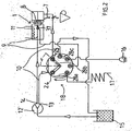
- the hydraulic cylinder is connected to a hydraulic control circuit 10 which can be configured to allow the admission of fluids into the cylinder body or its evacuation according to the operating phases.
- the pressurization of the fluid (here constituted by water) is carried out by a pump hydraulic 12 advantageously common with the pump used for the injection of hot water into the brewing chamber.
- the pump 12 is supplied with water by a source in the form of a tank represented by the reference numeral 15 in FIGS. 1 to 3. Downstream of the pump 12, a boiler 11 is present to ensure the supply of the water temperature before injection into the infusion chamber 1.
- a hot water outlet 16 may also be provided to ensure the delivery of hot water to the user or the production of steam according to the state of actuation and activation of the pump.
- a hot water distribution circuit for the part related to the production of drinks, the delivery of hot water, and the production of steam
- a hydraulic control circuit for actuating the closing means
- This valve 18 is shown in different states in FIGS. 1 to 3.
- valve 18 comprises a plurality of connection channels to the elements of the circuits.
- the valve 18 includes a connection channel 25 to the hydraulic cylinder 4 and a connection channel 26 to a purge circuit 27.
- a connection channel 24 is provided for connecting the valve 18 to an outlet 13 of the pump 12 to admit water under pressure for the control of the hydraulic cylinder 4.
- the valve 18 includes a connection channel 21 to this circuit, coming from the boiler 11.
- the circuit 9 can be connected via the valve 18 with a discharge outlet 17 via a connection channel 22.
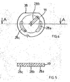
- the valve 18 is constituted from two parts 19, 20, well represented respectively in FIGS. 4, 5 and 6 to 8.
- the part 20 is fixed and receives the various connection channels previously indicated in the form of through holes.
- the portion 19 is rotatably mounted to provide a plurality of circuit configurations according to the relative angular position it occupies with respect to the fixed portion 20.
- the communication of different connection channels 21 to 26, have on the fixed part 20 is effected by means of communication here in the form of oblong blind holes 28 a, b, c, which stand out particularly from FIGS. 4 and 5.
- the oblong hole 28c ensures communication between the connection channels 25 , 26, or 26 and 23, according to the relative positions of the movable portion 19 and the fixed portion 20.
- the oblong hole 28b ensures the communication of the connection path 24 (from the pump 12) and the connection way 25 (to the hydraulic cylinder 4).
- the oblong hole 28a allows the communication channel 21 and the connection channel 22 to be put in communication to open the discharge circuit 17 or of the channel 21 with the channel 23 to produce hot water or water. steam.
- the communication command of the valve 18 can be operated in different ways, and in particular by motorized actuation or, more simply, by means of a manually operable lever 35, an example of which is shown in FIG. also illustrated an example of mounting of the valve 18.
- the fixed portion 20 is attached to a casing 33 connecting the connecting tracks 21 to 26.
- the seal is provided by a seal 32 for example silicone.
- the working face that which comprises the oblong holes 28a, b, c
- the disc portion forms a rotation drive under the effect of the lever 35.
- the power transmission between the lever 35 and the movable portion 19 is effected by a coupler 31 which also allows the assembly of all on a support 30.
- FIG. 1 This configuration is illustrated in Figure 1.
- the machine is not in the production position, in particular, a pod 8 is here being introduced but is not yet in the brewing chamber 1.
- the closing means of the infusion chamber 1 are inactivated, which is represented by a retracted position of the piston 5 of the cylinder 4.
- the pump 12 is also inactive, and the valve is such that the connection channels 24 and 25 are are not connected, avoiding the actuation of the cylinder 4.
- the channel 24 is in communication with the connection channel 26 ensuring the purge circuit 27 of the hydraulic cylinder 4 by return to the water source 15.
- the boiler 11 and the discharge outlet 17 are in communication in order to avoid any overpressure in the boiler 11, by means of a communication of the heating channels. connection 21 and 22, through the slot 28 a.
- a dose 8 has been introduced and is present in the infusion chamber 1.
- the movable portion 19 of the valve 18 has been rotated in the direction indicated by the arrow in FIG. 2. This rotation ensures through the oblong hole 28b, the connection of the connection channels 24 and 25, so as to supply the hydraulic cylinder 4 with pressurized water from the pump 12.
- This supply of the inlet 6 of the cylinder has the effect of causing the translation of the piston 5 which ensures the closure of the infusion chamber 1 by the movement of the movable portion 3 of said chamber 1.
- a valve 37 calibrated at a predetermined pressure is located at the outlet of the boiler 11, upstream of the brewing chamber 1, avoids the circulation of water to the brewing chamber 1 before having reached a pressure predetermined for the valve does not open before closing the infusion chamber under the actuation of the cylinder 4.
- valve 37 opens and ensures the circulation of water between the boiler 11 and the brewing chamber 1 to produce the hot drink that flows through the outlet 7.
- connection channels 21, 22, and 23 are not connected to the outlet of the boiler 11.
- the machine according to the invention is equipped with an outlet 16 for delivering hot water or steam to the user. Delivery of hot water is effected with full actuation of the pump 12. For the production of steam, the pump 12 is inactive or active intermittently.
- the valve 18 is here configured so as to put in communication the connection tracks 21 and 23 ensuring the flow of the hot water from the boiler 11 to the outlet 16.
- the other channels are not in communication.
- the jack 4 remains inactive since the connection path 24 is plugged.
- the infusion chamber 1 remains open and waiting for the introduction of a dose 8.
Landscapes
- Engineering & Computer Science (AREA)
- Food Science & Technology (AREA)
- Mechanical Engineering (AREA)
- Apparatus For Making Beverages (AREA)
- Beverage Vending Machines With Cups, And Gas Or Electricity Vending Machines (AREA)
- Devices For Dispensing Beverages (AREA)
- Non-Alcoholic Beverages (AREA)
- Vending Machines For Individual Products (AREA)
- Cookers (AREA)
Claims (7)
- Vorrichtung für die Herstellung von Getränken durch Aufgießen von warmem Wasser, mit einer Aufgusskammer (1), die mit einem Warmwasser-Verteilerkreis (9) verbunden ist, der aufgebaut ist aus einem Ventil (18) mit Verbindungswegen (21, 22) zum Warmwasser-Verteilerkreis (9) und zu einem Warmwasser-Ausgabeausgang (17) sowie mit einer Verbindungseinrichtung des Verbindungsweges (21) mit dem Warmwasser-Verteilerkreis (9) mit dem Verbindungsweg (22) des Warmwasser-Ausgabeausgangs (17), wobei das Ventil (18) einen festen Teil (20), der mit den Verbindungswegen (21, 22) ausgestattet ist, und einen beweglichen Teil (19), der relativ zum festen Teil (20) eine Drehung ausführt und mit der Verbindungseinrichtung ausgestattet ist, aufweist, wobei die Relativstellung des festen Teils (20) und des beweglichen Teils (19) die Konfiguration des Warmwasser-Verteilerkreises (9) definiert,
dadurch gekennzeichnet, dass- die Aufgusskammer geöffnet oder geschlossen werden kann durch eine Schließeinrichtung, die mit einer hydraulischen Antriebsschaltung (10) verbunden ist, wobei der Warmwasser-Verteilerkreis (9) und die hydraulische Antriebsschaltung (10) durch dasselbe Ventil (10) gebildet sind;- die Schließeinrichtung einen Hydraulikzylinder (4) aufweist, der durch eine Hydraulikpumpe (12) betätigt wird;- das Ventil (18) Verbindungswege (24, 25, 26) mit dem Ausgang (13) der Hydraulikpumpe (12), mit dem Hydraulikzylinder (4) und mit einem Zylinderentleerungskreis (27) aufweist;- das Ventil (18) eine Verbindungseinrichtung des Verbindungsweges (25) des Hydraulikzylinders (4) entweder mit dem Verbindungsweg (24) des Ausgangs der Hydraulikpumpe (12) oder mit dem Verbindungsweg (26) des Entleerungskreises (27) des Zylinders (4) aufweist. - Vorrichtung nach Anspruch 1,
dadurch gekennzeichnet,
dass das Ventil (18) einen Verbindungsweg (23) eines Warmwasserausgangs (16) und eine Verbindungseinrichtung des Verbindungsweges (21) des Warmwasser-Verteilerkreises (9) entweder mit dem Verbindungsweg (22) des Warmwasser-Ausgabeausgangs (17) oder mit dem Verbindungsweg (23) des Warmwasserausgangs (16) aufweist. - Vorrichtung nach Anspruch 1 oder 2,
dadurch gekennzeichnet,
dass der bewegliche Teil (19) durch einen Hebel (35) zur Drehung betätigt wird. - Vorrichtung nach einem der Ansprüche 1 bis 3,
dadurch gekennzeichnet,
dass die Hydraulikpumpe (12) mit der hydraulischen Antriebschaltung (10) und mit dem Warmwasser-Verteilerkreis (9) in Verbindung steht. - Vorrichtung nach einem der Ansprüche 1 bis 4,
dadurch gekennzeichnet,
dass der Warmwasser-Verteilerkreis (9) und die hydraulische Antriebschaltung (10) von einer gleichen Wasserquelle (15) gespeist werden. - Vorrichtung nach einem der Ansprüche 2 bis 4 in Verbindung mit Anspruch 5,
dadurch gekennzeichnet,
dass der Entleerungskreis (27) des Zylinders (4) mit der Wasserquelle (15) verbunden ist. - Vorrichtung nach einem der Ansprüche 1 bis 6,
dadurch gekennzeichnet,
dass der Warmwasser-Verteilerkreis (9) einen Heizkessel (11) aufweist, der mit einem Einspritzkreis in der Aufgusskammer (1) verbunden ist, wobei der Einspritzkreis eine Klappe (37) aufweist, die auf einen vorbestimmten Druck geeicht ist.
Applications Claiming Priority (3)
| Application Number | Priority Date | Filing Date | Title |
|---|---|---|---|
| FR0211665A FR2844441B1 (fr) | 2002-09-16 | 2002-09-16 | Machine pour la production de boisson par infusion d'eau chaude |
| FR0211665 | 2002-09-16 | ||
| PCT/FR2003/050054 WO2004041039A1 (fr) | 2002-09-16 | 2003-09-12 | Machine pour la production de boisson par infusion d'eau chaude |
Publications (2)
| Publication Number | Publication Date |
|---|---|
| EP1545278A1 EP1545278A1 (de) | 2005-06-29 |
| EP1545278B1 true EP1545278B1 (de) | 2007-11-07 |
Family
ID=31897508
Family Applications (1)
| Application Number | Title | Priority Date | Filing Date |
|---|---|---|---|
| EP03780267A Expired - Lifetime EP1545278B1 (de) | 2002-09-16 | 2003-09-12 | Gerät für die herstellung von getränken durch aufbrühen von heissem wasser |
Country Status (7)
| Country | Link |
|---|---|
| EP (1) | EP1545278B1 (de) |
| AT (1) | ATE377372T1 (de) |
| AU (1) | AU2003288360A1 (de) |
| DE (1) | DE60317357T2 (de) |
| ES (1) | ES2297246T3 (de) |
| FR (1) | FR2844441B1 (de) |
| WO (1) | WO2004041039A1 (de) |
Cited By (2)
| Publication number | Priority date | Publication date | Assignee | Title |
|---|---|---|---|---|
| ITRM20110329A1 (it) * | 2011-06-23 | 2012-12-24 | Gardosi Massimiliano | Compensatore per apparecchi erogatori di bevande calde, preferibilmente pre-dosate, in particolare per macchine da caffè a cialda. |
| WO2018158179A1 (en) * | 2017-02-28 | 2018-09-07 | Nestec Sa | Dispenser with parallel dispensing paths |
Families Citing this family (13)
| Publication number | Priority date | Publication date | Assignee | Title |
|---|---|---|---|---|
| ES2537120T3 (es) | 2009-10-05 | 2015-06-02 | Nestec S.A. | Dispositivo de extracción de cartucho |
| DK2506745T3 (da) | 2009-12-01 | 2013-12-16 | Nestec Sa | Patron-ekstraktionsindretning |
| EP2353469A1 (de) | 2010-02-03 | 2011-08-10 | Nestec S.A. | Getränkeherstellungsmaschine für große Getränkemengen |
| FR2960406B1 (fr) * | 2010-05-25 | 2013-01-11 | Cie Mediterraneenne Des Cafes | Systeme de production de boissons par infusion |
| EP2575573B1 (de) * | 2010-05-25 | 2015-07-08 | Compagnie Mediterraneenne Des Cafes | System zur herstellung von getränken durch infusion |
| IT1402180B1 (it) * | 2010-09-09 | 2013-08-28 | Sgl Italia S R L Con Unico Socio | Gruppo infusore per la produzione di una bevanda |
| AU2012298548A1 (en) | 2011-08-25 | 2014-02-06 | Nestec S.A. | Cartridge removal system |
| US20140326361A1 (en) | 2011-08-25 | 2014-11-06 | Nestec S.A. | Long-lasting cartridge piercer |
| WO2013026856A1 (en) | 2011-08-25 | 2013-02-28 | Nestec S.A. | Cartridge positioning system |
| CA2842533C (en) | 2011-08-25 | 2019-06-04 | Nestec S.A. | Cartridge chamber of extraction system |
| DE102013210108A1 (de) * | 2013-05-29 | 2014-12-04 | BSH Bosch und Siemens Hausgeräte GmbH | Kaffeevollautomat mit motorisch verstellbarem Mehrwegventil |
| US10750898B2 (en) | 2015-07-03 | 2020-08-25 | Saga Coffee S.P.A. | Beverage producing machine |
| WO2025120135A1 (en) | 2023-12-07 | 2025-06-12 | Societe Des Produits Nestle S.A. | Reliable capsule removal system |
Family Cites Families (6)
| Publication number | Priority date | Publication date | Assignee | Title |
|---|---|---|---|---|
| CH404126A (it) * | 1962-09-01 | 1965-12-15 | Organizzazione Novi S R L | Macchina automatica per la produzione di caffè espresso |
| FR2709655B1 (fr) | 1993-09-06 | 1995-11-24 | Cafes Cie Mediterraneenne | Machine à café express utilisant un conditionnement de café moulu du type pastille pré-dosée. |
| DE4427745A1 (de) * | 1994-08-05 | 1996-02-01 | Braun Ag | Mehrscheiben-Verteilerventil |
| FR2801774B1 (fr) * | 1999-12-01 | 2004-02-20 | Moulinex Sa | Ensemble de distribution d'eau de machine a cafe espresso |
| DK1219217T3 (da) * | 2000-12-29 | 2004-01-05 | Sgl Italia Srl | Kaffemaskine |
| CH694265A5 (fr) | 2001-01-24 | 2004-10-29 | Monodor Sa | Dispositif d'injection d'eau pour un appareil pour la confection d'une boisson à partir d'une capsule contenant le produit à extraire. |
-
2002
- 2002-09-16 FR FR0211665A patent/FR2844441B1/fr not_active Expired - Fee Related
-
2003
- 2003-09-12 ES ES03780267T patent/ES2297246T3/es not_active Expired - Lifetime
- 2003-09-12 WO PCT/FR2003/050054 patent/WO2004041039A1/fr not_active Ceased
- 2003-09-12 AU AU2003288360A patent/AU2003288360A1/en not_active Abandoned
- 2003-09-12 DE DE60317357T patent/DE60317357T2/de not_active Expired - Lifetime
- 2003-09-12 EP EP03780267A patent/EP1545278B1/de not_active Expired - Lifetime
- 2003-09-12 AT AT03780267T patent/ATE377372T1/de not_active IP Right Cessation
Cited By (2)
| Publication number | Priority date | Publication date | Assignee | Title |
|---|---|---|---|---|
| ITRM20110329A1 (it) * | 2011-06-23 | 2012-12-24 | Gardosi Massimiliano | Compensatore per apparecchi erogatori di bevande calde, preferibilmente pre-dosate, in particolare per macchine da caffè a cialda. |
| WO2018158179A1 (en) * | 2017-02-28 | 2018-09-07 | Nestec Sa | Dispenser with parallel dispensing paths |
Also Published As
| Publication number | Publication date |
|---|---|
| ATE377372T1 (de) | 2007-11-15 |
| DE60317357T2 (de) | 2008-08-21 |
| FR2844441B1 (fr) | 2006-03-31 |
| EP1545278A1 (de) | 2005-06-29 |
| FR2844441A1 (fr) | 2004-03-19 |
| AU2003288360A1 (en) | 2004-06-07 |
| WO2004041039A1 (fr) | 2004-05-21 |
| DE60317357D1 (de) | 2007-12-20 |
| ES2297246T3 (es) | 2008-05-01 |
Similar Documents
| Publication | Publication Date | Title |
|---|---|---|
| EP1545278B1 (de) | Gerät für die herstellung von getränken durch aufbrühen von heissem wasser | |
| EP1583446B1 (de) | Vorrichtung und maschine zum extrahieren einer substanz für die zubereitung eines getränkes | |
| EP1480540B1 (de) | Vorrichtung zur herstellung von infusionsgetränken | |
| CA2435445C (fr) | Dispositif d'injection d'eau pour un appareil pour la confection d'une boisson a partir d'une capsule | |
| EP1967099B1 (de) | Vorrichtung zur Herstellung eines flüssigen Lebensmittels aus einer Kapsel | |
| WO2008046740A1 (fr) | Ensemble comportant un appareil et une capsule jetable pour produire une boisson par infusion, et capsule pour un tel ensemble | |
| EP1867258A2 (de) | Pulverisierender Produktverteiler mit abnehmbaren Behälter | |
| FR2912664A1 (fr) | Appareil destine a confectionner une infusion. | |
| FR2960405A1 (fr) | Dispositif d'infusion a variation de pression | |
| EP1635679B1 (de) | Vorrichtung zur herstellung von infusionsgetränken | |
| EP1635681B1 (de) | Vorrichtung zur herstellung eines getränks durch aufgiessen | |
| EP3013192A1 (de) | Vorrichtung zur herstellung von aufgussgetränken mit einem injektionsschlauch für die aufgusskammer | |
| EP2575560B1 (de) | System zur herstellung von aufgussgetränken | |
| EP2385778A1 (de) | Perkolationsvorrichtung | |
| WO2007036634A1 (fr) | Adoucisseur d'eau a double mode de regeneration | |
| EP2575573B1 (de) | System zur herstellung von getränken durch infusion | |
| FR2639205A1 (fr) | Machine a cafe automatique composee d'un plateau mobile circulaire perce d'alveoles dispose entre deux plateaux fixes, le mouvement circulaire assurant les differentes phases de la preparation du cafe avec une etancheite de chaque alveole | |
| EP2575565B2 (de) | System zur herstellung von getränken durch infusion | |
| EP1677652B1 (de) | Perfektionierung einer automatischen kaffeemaschine mit einer bewegbaren brühkopfeinheit | |
| FR2960406A1 (fr) | Systeme de production de boissons par infusion | |
| WO2003086650A1 (fr) | Pompe de distribution de produit fluide | |
| WO2010015743A1 (fr) | Motopompe a ecoulement axial | |
| WO2012056158A1 (fr) | Appareil de confection d'infusions du type a retournement | |
| FR3156463A1 (fr) | Système de chasse d’eau |
Legal Events
| Date | Code | Title | Description |
|---|---|---|---|
| PUAI | Public reference made under article 153(3) epc to a published international application that has entered the european phase |
Free format text: ORIGINAL CODE: 0009012 |
|
| 17P | Request for examination filed |
Effective date: 20050311 |
|
| AK | Designated contracting states |
Kind code of ref document: A1 Designated state(s): AT BE BG CH CY CZ DE DK EE ES FI FR GB GR HU IE IT LI LU MC NL PT RO SE SI SK TR |
|
| AX | Request for extension of the european patent |
Extension state: AL LT LV MK |
|
| DAX | Request for extension of the european patent (deleted) | ||
| GRAP | Despatch of communication of intention to grant a patent |
Free format text: ORIGINAL CODE: EPIDOSNIGR1 |
|
| RIN1 | Information on inventor provided before grant (corrected) |
Inventor name: BLANC, JEAN-PIERRE,OFF. MEDIT. DE BREV. D'I.&M. Inventor name: FERRIER, CHRISTIAN,OFF. MEDIT. DE BREV. D'I.&M. |
|
| GRAS | Grant fee paid |
Free format text: ORIGINAL CODE: EPIDOSNIGR3 |
|
| GRAA | (expected) grant |
Free format text: ORIGINAL CODE: 0009210 |
|
| AK | Designated contracting states |
Kind code of ref document: B1 Designated state(s): AT BE BG CH CY CZ DE DK EE ES FI FR GB GR HU IE IT LI LU MC NL PT RO SE SI SK TR |
|
| REG | Reference to a national code |
Ref country code: GB Ref legal event code: FG4D Free format text: NOT ENGLISH |
|
| REG | Reference to a national code |
Ref country code: IE Ref legal event code: FG4D Free format text: LANGUAGE OF EP DOCUMENT: FRENCH |
|
| REG | Reference to a national code |
Ref country code: CH Ref legal event code: EP |
|
| REF | Corresponds to: |
Ref document number: 60317357 Country of ref document: DE Date of ref document: 20071220 Kind code of ref document: P |
|
| REG | Reference to a national code |
Ref country code: CH Ref legal event code: NV Representative=s name: PATENTS & TECHNOLOGY SURVEYS SA |
|
| GBT | Gb: translation of ep patent filed (gb section 77(6)(a)/1977) |
Effective date: 20080211 |
|
| PG25 | Lapsed in a contracting state [announced via postgrant information from national office to epo] |
Ref country code: SE Free format text: LAPSE BECAUSE OF FAILURE TO SUBMIT A TRANSLATION OF THE DESCRIPTION OR TO PAY THE FEE WITHIN THE PRESCRIBED TIME-LIMIT Effective date: 20080207 |
|
| REG | Reference to a national code |
Ref country code: ES Ref legal event code: FG2A Ref document number: 2297246 Country of ref document: ES Kind code of ref document: T3 |
|
| PG25 | Lapsed in a contracting state [announced via postgrant information from national office to epo] |
Ref country code: SI Free format text: LAPSE BECAUSE OF FAILURE TO SUBMIT A TRANSLATION OF THE DESCRIPTION OR TO PAY THE FEE WITHIN THE PRESCRIBED TIME-LIMIT Effective date: 20071107 Ref country code: BG Free format text: LAPSE BECAUSE OF FAILURE TO SUBMIT A TRANSLATION OF THE DESCRIPTION OR TO PAY THE FEE WITHIN THE PRESCRIBED TIME-LIMIT Effective date: 20080207 |
|
| PG25 | Lapsed in a contracting state [announced via postgrant information from national office to epo] |
Ref country code: AT Free format text: LAPSE BECAUSE OF FAILURE TO SUBMIT A TRANSLATION OF THE DESCRIPTION OR TO PAY THE FEE WITHIN THE PRESCRIBED TIME-LIMIT Effective date: 20071107 |
|
| PG25 | Lapsed in a contracting state [announced via postgrant information from national office to epo] |
Ref country code: DK Free format text: LAPSE BECAUSE OF FAILURE TO SUBMIT A TRANSLATION OF THE DESCRIPTION OR TO PAY THE FEE WITHIN THE PRESCRIBED TIME-LIMIT Effective date: 20071107 Ref country code: CZ Free format text: LAPSE BECAUSE OF FAILURE TO SUBMIT A TRANSLATION OF THE DESCRIPTION OR TO PAY THE FEE WITHIN THE PRESCRIBED TIME-LIMIT Effective date: 20071107 |
|
| PG25 | Lapsed in a contracting state [announced via postgrant information from national office to epo] |
Ref country code: RO Free format text: LAPSE BECAUSE OF FAILURE TO SUBMIT A TRANSLATION OF THE DESCRIPTION OR TO PAY THE FEE WITHIN THE PRESCRIBED TIME-LIMIT Effective date: 20071107 Ref country code: SK Free format text: LAPSE BECAUSE OF FAILURE TO SUBMIT A TRANSLATION OF THE DESCRIPTION OR TO PAY THE FEE WITHIN THE PRESCRIBED TIME-LIMIT Effective date: 20071107 |
|
| PLBE | No opposition filed within time limit |
Free format text: ORIGINAL CODE: 0009261 |
|
| STAA | Information on the status of an ep patent application or granted ep patent |
Free format text: STATUS: NO OPPOSITION FILED WITHIN TIME LIMIT |
|
| PG25 | Lapsed in a contracting state [announced via postgrant information from national office to epo] |
Ref country code: PT Free format text: LAPSE BECAUSE OF FAILURE TO SUBMIT A TRANSLATION OF THE DESCRIPTION OR TO PAY THE FEE WITHIN THE PRESCRIBED TIME-LIMIT Effective date: 20080407 |
|
| REG | Reference to a national code |
Ref country code: IE Ref legal event code: FD4D |
|
| 26N | No opposition filed |
Effective date: 20080808 |
|
| PG25 | Lapsed in a contracting state [announced via postgrant information from national office to epo] |
Ref country code: IE Free format text: LAPSE BECAUSE OF FAILURE TO SUBMIT A TRANSLATION OF THE DESCRIPTION OR TO PAY THE FEE WITHIN THE PRESCRIBED TIME-LIMIT Effective date: 20071107 |
|
| PG25 | Lapsed in a contracting state [announced via postgrant information from national office to epo] |
Ref country code: GR Free format text: LAPSE BECAUSE OF FAILURE TO SUBMIT A TRANSLATION OF THE DESCRIPTION OR TO PAY THE FEE WITHIN THE PRESCRIBED TIME-LIMIT Effective date: 20080208 |
|
| PG25 | Lapsed in a contracting state [announced via postgrant information from national office to epo] |
Ref country code: FI Free format text: LAPSE BECAUSE OF FAILURE TO SUBMIT A TRANSLATION OF THE DESCRIPTION OR TO PAY THE FEE WITHIN THE PRESCRIBED TIME-LIMIT Effective date: 20071107 |
|
| PG25 | Lapsed in a contracting state [announced via postgrant information from national office to epo] |
Ref country code: EE Free format text: LAPSE BECAUSE OF FAILURE TO SUBMIT A TRANSLATION OF THE DESCRIPTION OR TO PAY THE FEE WITHIN THE PRESCRIBED TIME-LIMIT Effective date: 20071107 Ref country code: MC Free format text: LAPSE BECAUSE OF NON-PAYMENT OF DUE FEES Effective date: 20080930 |
|
| PG25 | Lapsed in a contracting state [announced via postgrant information from national office to epo] |
Ref country code: CY Free format text: LAPSE BECAUSE OF FAILURE TO SUBMIT A TRANSLATION OF THE DESCRIPTION OR TO PAY THE FEE WITHIN THE PRESCRIBED TIME-LIMIT Effective date: 20071107 |
|
| PG25 | Lapsed in a contracting state [announced via postgrant information from national office to epo] |
Ref country code: LU Free format text: LAPSE BECAUSE OF NON-PAYMENT OF DUE FEES Effective date: 20080912 Ref country code: HU Free format text: LAPSE BECAUSE OF FAILURE TO SUBMIT A TRANSLATION OF THE DESCRIPTION OR TO PAY THE FEE WITHIN THE PRESCRIBED TIME-LIMIT Effective date: 20080508 |
|
| PG25 | Lapsed in a contracting state [announced via postgrant information from national office to epo] |
Ref country code: TR Free format text: LAPSE BECAUSE OF FAILURE TO SUBMIT A TRANSLATION OF THE DESCRIPTION OR TO PAY THE FEE WITHIN THE PRESCRIBED TIME-LIMIT Effective date: 20071107 |
|
| REG | Reference to a national code |
Ref country code: CH Ref legal event code: PFA Owner name: COMPAGNIE MEDITERRANEENNE DES CAFES S.A. Free format text: COMPAGNIE MEDITERRANEENNE DES CAFES S.A.#ZONE INDUSTRIELLE, 9EME RUE#06510 CARROS (FR) -TRANSFER TO- COMPAGNIE MEDITERRANEENNE DES CAFES S.A.#ZONE INDUSTRIELLE, 9EME RUE#06510 CARROS (FR) |
|
| REG | Reference to a national code |
Ref country code: FR Ref legal event code: PLFP Year of fee payment: 14 |
|
| PGFP | Annual fee paid to national office [announced via postgrant information from national office to epo] |
Ref country code: GB Payment date: 20160907 Year of fee payment: 14 Ref country code: CH Payment date: 20160914 Year of fee payment: 14 Ref country code: NL Payment date: 20160913 Year of fee payment: 14 Ref country code: DE Payment date: 20160907 Year of fee payment: 14 |
|
| PGFP | Annual fee paid to national office [announced via postgrant information from national office to epo] |
Ref country code: BE Payment date: 20160913 Year of fee payment: 14 Ref country code: ES Payment date: 20160915 Year of fee payment: 14 |
|
| REG | Reference to a national code |
Ref country code: FR Ref legal event code: PLFP Year of fee payment: 15 |
|
| REG | Reference to a national code |
Ref country code: DE Ref legal event code: R119 Ref document number: 60317357 Country of ref document: DE |
|
| REG | Reference to a national code |
Ref country code: CH Ref legal event code: PL |
|
| REG | Reference to a national code |
Ref country code: NL Ref legal event code: MM Effective date: 20171001 |
|
| GBPC | Gb: european patent ceased through non-payment of renewal fee |
Effective date: 20170912 |
|
| REG | Reference to a national code |
Ref country code: BE Ref legal event code: MM Effective date: 20170930 |
|
| PG25 | Lapsed in a contracting state [announced via postgrant information from national office to epo] |
Ref country code: NL Free format text: LAPSE BECAUSE OF NON-PAYMENT OF DUE FEES Effective date: 20171001 |
|
| PG25 | Lapsed in a contracting state [announced via postgrant information from national office to epo] |
Ref country code: CH Free format text: LAPSE BECAUSE OF NON-PAYMENT OF DUE FEES Effective date: 20170930 Ref country code: DE Free format text: LAPSE BECAUSE OF NON-PAYMENT OF DUE FEES Effective date: 20180404 Ref country code: GB Free format text: LAPSE BECAUSE OF NON-PAYMENT OF DUE FEES Effective date: 20170912 Ref country code: LI Free format text: LAPSE BECAUSE OF NON-PAYMENT OF DUE FEES Effective date: 20170930 |
|
| PG25 | Lapsed in a contracting state [announced via postgrant information from national office to epo] |
Ref country code: BE Free format text: LAPSE BECAUSE OF NON-PAYMENT OF DUE FEES Effective date: 20170930 |
|
| REG | Reference to a national code |
Ref country code: FR Ref legal event code: PLFP Year of fee payment: 16 |
|
| REG | Reference to a national code |
Ref country code: ES Ref legal event code: FD2A Effective date: 20181019 |
|
| PGFP | Annual fee paid to national office [announced via postgrant information from national office to epo] |
Ref country code: IT Payment date: 20180622 Year of fee payment: 16 |
|
| PG25 | Lapsed in a contracting state [announced via postgrant information from national office to epo] |
Ref country code: ES Free format text: LAPSE BECAUSE OF NON-PAYMENT OF DUE FEES Effective date: 20170913 |
|
| PG25 | Lapsed in a contracting state [announced via postgrant information from national office to epo] |
Ref country code: IT Free format text: LAPSE BECAUSE OF NON-PAYMENT OF DUE FEES Effective date: 20190912 |
|
| PGFP | Annual fee paid to national office [announced via postgrant information from national office to epo] |
Ref country code: FR Payment date: 20220930 Year of fee payment: 20 |