EP2575573B1 - System zur herstellung von getränken durch infusion - Google Patents
System zur herstellung von getränken durch infusion Download PDFInfo
- Publication number
- EP2575573B1 EP2575573B1 EP11722782.7A EP11722782A EP2575573B1 EP 2575573 B1 EP2575573 B1 EP 2575573B1 EP 11722782 A EP11722782 A EP 11722782A EP 2575573 B1 EP2575573 B1 EP 2575573B1
- Authority
- EP
- European Patent Office
- Prior art keywords
- infusion
- fluid
- chamber
- outlet
- solenoid valve
- Prior art date
- Legal status (The legal status is an assumption and is not a legal conclusion. Google has not performed a legal analysis and makes no representation as to the accuracy of the status listed.)
- Active
Links
Images


Classifications
-
- A—HUMAN NECESSITIES
- A47—FURNITURE; DOMESTIC ARTICLES OR APPLIANCES; COFFEE MILLS; SPICE MILLS; SUCTION CLEANERS IN GENERAL
- A47J—KITCHEN EQUIPMENT; COFFEE MILLS; SPICE MILLS; APPARATUS FOR MAKING BEVERAGES
- A47J31/00—Apparatus for making beverages
- A47J31/24—Coffee-making apparatus in which hot water is passed through the filter under pressure, i.e. in which the coffee grounds are extracted under pressure
- A47J31/34—Coffee-making apparatus in which hot water is passed through the filter under pressure, i.e. in which the coffee grounds are extracted under pressure with hot water under liquid pressure
- A47J31/36—Coffee-making apparatus in which hot water is passed through the filter under pressure, i.e. in which the coffee grounds are extracted under pressure with hot water under liquid pressure with mechanical pressure-producing means
- A47J31/3604—Coffee-making apparatus in which hot water is passed through the filter under pressure, i.e. in which the coffee grounds are extracted under pressure with hot water under liquid pressure with mechanical pressure-producing means with a mechanism arranged to move the brewing chamber between loading, infusing and ejecting stations
- A47J31/3609—Loose coffee being employed
- A47J31/3614—Means to perform transfer from a loading position to an infusing position
-
- A—HUMAN NECESSITIES
- A47—FURNITURE; DOMESTIC ARTICLES OR APPLIANCES; COFFEE MILLS; SPICE MILLS; SUCTION CLEANERS IN GENERAL
- A47J—KITCHEN EQUIPMENT; COFFEE MILLS; SPICE MILLS; APPARATUS FOR MAKING BEVERAGES
- A47J31/00—Apparatus for making beverages
- A47J31/44—Parts or details or accessories of beverage-making apparatus
- A47J31/46—Dispensing spouts, pumps, drain valves or like liquid transporting devices
- A47J31/461—Valves, e.g. drain valves
-
- A—HUMAN NECESSITIES
- A47—FURNITURE; DOMESTIC ARTICLES OR APPLIANCES; COFFEE MILLS; SPICE MILLS; SUCTION CLEANERS IN GENERAL
- A47J—KITCHEN EQUIPMENT; COFFEE MILLS; SPICE MILLS; APPARATUS FOR MAKING BEVERAGES
- A47J31/00—Apparatus for making beverages
- A47J31/44—Parts or details or accessories of beverage-making apparatus
- A47J31/46—Dispensing spouts, pumps, drain valves or like liquid transporting devices
- A47J31/469—Details of hydraulic circuits
Definitions
- the present invention relates to a device for producing beverages by infusing a product in the form of doses.
- the invention relates more particularly to machines in which the extraction of the product to be infused is carried out under pressure. This is the case of espresso machines in which coffee is brewed at a pressure of between 8 and 20 bars and more generally greater than 10 bars. A machine of this type is described in EP 1795095 A1 .
- These machines comprise an infusion chamber for receiving the product to be infused, a pumped to raise the pressure of the fluid in the circuit as well as heating means arranged between the infusion chamber and the pump. These heating means must make it possible to raise the temperature of the liquid to about 90 ° C. To satisfy the tastes of the various users of an espresso-type coffee machine, it is possible to add to this machine a nozzle delivering hot water at atmospheric pressure to dilute the contents of a cup of coffee previously infused at high pressure without reducing the temperature. This is called “lengthening the coffee”.
- the present invention provides a beverage production machine by infusion of a product to be infused as defined in claim 1.
- the machine according to the invention makes it possible to feed the infusion chamber with hot water under pressure when the pump is running, that the outlet solenoid valve is closed, thereby allowing the fluid to rise in pressure in the chamber. hydraulic circuit until reaching the infusion pressure threshold. The valve then opens, allowing the introduction of hot water under pressure inside the brewing chamber.
- the machine according to the invention in another phase of operation, also makes it possible to deliver a fluid heated at low pressure when the pump is running and the outlet solenoid valve is open.
- the opening of the outlet solenoid valve prevents the pressure rise of the fluid inside the circuit.
- the calibrated valve does not open and prevents the introduction of fluid into the brewing chamber.
- the invention comprises only one boiler and has a particularly simple architecture. It induces a limited cost and is particularly advantageous even for machines whose use is not intensive, typically, domestic or semi-professional machines such as office machines, hotel etc.
- the claimed combination involving a solenoid valve and a calibrated valve offers particularly high reliability and is very easy to use.
- the same chamber portion provides power to the brewing chamber and is driven by the actuator, while allowing an independent supply between the brewing chamber and the thrust chamber.
- the latter can thus be fed with unheated fluid.
- the return of the actuator thus expels unheated water. The energy consumption is reduced while limiting the overall size.
- the pump delivers no pressure.
- the pump delivers a pressure tending to close the brewing chamber.
- the figure 5 represents the brewing phase, the brewing chamber is closed and the boiler delivers heated water into the brewing chamber.
- the outlet solenoid valve is open, the solenoid discharge valve is closed, the pump and the boiler function to deliver low pressure heated fluid.
- FIG. 1 to 10 there is illustrated a beverage preparation machine according to the invention comprising an infusion system.
- upstream and downstream portions of space respectively before and after a point considered relative to the flow of a flow in the machine during a cycle of preparation of a drink will be described as upstream and downstream.
- low pressure is defined as insufficient pressure to prepare a drink by infusion under pressure.
- a low pressure is less than 3 bars.
- the infused product for example the ground coffee
- the present invention is usable with various types of doses or packages.
- the perimeter of dose 1 is rigid.
- the invention applies regardless of the type of dose. It applies to doses having a flexible or rigid outer shell of the capsule type. It also applies to doses whose outer shell is able to disappear at least in part during the infusion, for example dissolution.
- Such a dose formed of an aggregate of infusing product such as coffee may be formed outside the machine or be constituted by a dedicated module of the machine.
- the infusion system according to the invention also referred to as an infusion group, comprises an infusion chamber 7 intended to receive a dose 1.
- the infusion chamber 7 comprises two chamber portions arranged to be mutually distant or brought closer together by an actuator 40 to respectively close or open the brewing chamber 7.
- half-chambers means parts that can be arranged in contact with each other or in contact with a dose 1 to form a sealed volume serving as an infusion chamber 7.
- the invention in no way implies that the two portions of chamber have any symmetry between them.
- one of the chamber portions is driven by a actuator 40 allowing mutual reconciliation and removal of the chamber portions.
- the first chamber portion 42 is carried by the actuator.
- the other chamber portion hereinafter referred to as the second chamber portion or fixed portion 22, is integral with a frame 20 of the machine.
- Each of the chamber portions has an end defining a periphery contained in a plane substantially perpendicular to the longitudinal axis 11.
- the direction comprising the main direction of movement of the actuator 40 will be referred to hereinafter as the longitudinal axis 11 or the longitudinal direction 11. It will be described as meaning before 12 the direction, along this axis 11, contributing to the mutual approximation of the two chamber portions and describe in the rear direction 13, the direction along this axis 11 allowing a mutual distance between the two chamber portions 22, 42.
- the longitudinal direction 11, the forward direction 12 and the rear direction 13 are represented in FIG. figure 1 .
- the first chamber portion 42 has a supply duct 24 connected to fluid supply means to be infused, typically hot water.
- the supply means form a hot water circuit comprising a tank, a boiler 500 making it possible to increase the temperature of a portion of the water coming from the tank to a desired temperature in view of its infusion in the brewing chamber 7, and a pump 400 for raising the pressure of the water in the circuit.
- the two chamber portions 42, 22 are held firmly in contact with one another and delimit a sealed volume for receiving the dose 1.
- the sealing can be achieved by applying the periphery of the two portions of the chamber around the perimeter of the dose 1 which then serves as a seal.
- the seal may also be provided or be reinforced sealing means reported.
- the second chamber portion 22 comprises a beverage discharge conduit 45 in fluid communication on the one hand with the interior of the brewing chamber 7 and with a drink outlet on the other hand.
- This exhaust duct 45 is intended to ensure the evacuation of the drink resulting from the infusion of the dose 1 to a container such as a coffee cup.
- the infusion chamber 7 After infusion, when the first chamber portion 42 is moved away from the second chamber portion 22, the infusion chamber 7 is opened, the dose 1 already infused is then no longer contained in the infusion chamber 7. This dose 1 is discharged from the infusion chamber 7 by gravity and falls into a recovery tank.
- the actuator 40 comprises a thrust chamber 100 intended to be supplied with a fluid under pressure from the pump. It is configured to drive the first portion 42 so as to control at least part of the closure of the infusion chamber 7 when the thrust chamber 100 is supplied with a pressure greater than a given pressure.
- the supply means 24, 104, 108, carried at least in part by the first chamber portion 42, are fluidically isolated from the thrust chamber 100.
- the feed fluid of the actuator is isolated from the heated fluid for infusion.
- the actuator does not flush heated water.
- the amount of heated water is reduced and the energy consumption of the machine is reduced.
- the system is configured so that the fluid supply means of the brewing chamber 7 and the actuator of the brewing chamber 7 are arranged on the same side of the brewing chamber.
- the feed means and the actuator are arranged behind the infusion chamber 7.
- the front face of the second portion 22 is integral with the frame.
- the second portion 22 can thus be positioned closer to a front face of a machine equipped with the system according to the invention.
- Front face refers to a face from which the user is intended to interact with the machine to prepare a drink.
- the front face has a recovery space of the infused beverage. This recovery space, not shown, is for example a laying plane of a cup.
- the exhaust duct 45 can also be limited.
- the invention makes it possible to dispense with a long exhaust duct or an extension chute usually necessary for feeding the infused beverage into a cup.
- a long exhaust duct or extension chute is usually required for the user to see his cup without part of the machine masking it. This positioning of the cup sufficiently in front of the machine is in practice necessary to properly position the cup, to control the level of filling and to appreciate the flow of the drink.
- the distance between the brewing chamber of the cup sufficiently impacts the temperature of the infused fluid to change the quality of the beverage obtained.
- a long distance tends to break the foam usually forming on the surface of a coffee.
- this distance makes it difficult to control the temperature of the drink on arrival in the cup.
- the taste perception of an infused drink, such as coffee depends largely on the temperature during the tasting.
- the invention makes it possible to shorten the distance separating the cup from the brewing chamber 7.
- the heat losses during the delivery of the beverage are therefore reduced, thereby improving the quality of the beverage obtained.
- the length of the conduit between the chamber and the cup increases heat transfer between the beverage and the machine.
- the colder the conduit the higher these heat transfers.
- the duct heats up, thereby reducing the heat transfers. Heat transfers therefore vary greatly depending on the use of the machine which prevents a good repeatability of the quality of the beverage obtained.
- the invention limits the amount of heated water discharged regardless of the stroke length of the actuator.
- the invention thus allows a sufficiently long stroke to ensure the entire displacement of the movable chamber portion 42.
- the invention thus makes it possible to dispense with a complementary device whose function is to carry out part of the displacement of the mobile chamber. The size of the machine is therefore reduced.
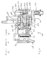
- the actuator driving the first chamber portion is a cylinder 40.
- the cylinder comprises a piston 114.
- the first chamber portion 42 is carried by the piston 114 of the cylinder 40.
- the cylinder 115 of the cylinder comprises a bottom 102 forming against the thrust surface 101 of the piston 114.
- the bottom 102 of the jack 40, its longitudinal walls and the thrust surface 101 define a thrust chamber 100.
- This thrust chamber 100 comprises at least one orifice 113 connecting the thrust chamber at a thrust fluid inlet 109 carried by the system 10 and intended to be connected to the pump.
- Activation of the pump causes pressurization of the pressure chamber 100, which causes the piston 114 to move forwards 12 and away from the bottom 102 of the cylinder 115.
- the system comprises return means of the jack 40.
- These means comprise a return spring 106 configured to provide the return back 13 of the piston 114 in the retracted position when the pressure drops in the thrust chamber 100.
- the spring 106 works in compression and extends longitudinally. Preferably, it is cylindrical and is surrounded by the piston 114. It is supported upstream on the piston and downstream on a stop 107 integral with the frame. In a not shown embodiment, this stop 107 contributes at least in part to guiding the piston.
- the figure 1 represents the cylinder in its retracted position, the return spring 106 being deployed and the piston being in contact with the bottom of the cylinder 115.
- the chamber is then completely open.
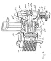
- the figures 2 represents the cylinder in its deployed position, the return spring 106 being retracted to the maximum and the piston being pushed forward 12 and away from the bottom of the cylinder 115.
- the chamber is then completely closed.
- the cylinder 115 has fitting means 103 projecting from the bottom 102 and extending towards the piston.
- the piston comprises a housing extending from the thrust surface 101.
- the housing and the fitting means 103 are shaped so that the fitting means 103 penetrate deeply into the housing when the cylinder 40 returns to the retracted position. .
- the piston 114 thus extends substantially longitudinally. Its upstream end is defined by a wall 116 facing the bottom of the cylinder 115. This upstream wall partially defines the thrust chamber 100. It is thus intended to be pushed forward by the fluid under pressure.
- the downstream end of the piston 114 is formed by the first chamber portion 42.
- the piston 114 also comprises a piston body 114 bearing the housing and intended to house the fitting means. This body 117 is substantially cylindrical and extends from the upstream wall 116 to the first chamber portion 42. Preferably, the body 117 of the piston 114 has a cavity 118 closed to reduce the weight and reduce the amount of material .
- the piston 114 illustrated in the figures is formed of two mutually assembled parts.
- a first portion forms the wall 116 and carries a male portion 119a of the body 117.
- This male portion 119a forms the housing.
- a second portion carries the first chamber portion 42 and a female portion 119b of the body 117.
- the portion female 119b of the body 117 engages on the male portion 119a of the body 117 to form the body 117 of the piston 114.
- the female portion 119b of the body 117 has a cavity open at its upstream end. This upstream end is configured to engage male portion 119a of body 117 to close cavity 118.
- the downstream end of the fitting means 103 is inserted into the housing of the piston 114.
- Seals 110 disposed between the fitting means 103 and the piston 114 permanently seal the passage 105.
- these seals 110 are mounted on the fitting means, near the downstream end thereof.
- the fitting means 103 comprise an internal supply channel 104.
- An upstream end of the channel 104 is fluidly connected to a fluid inlet 108 connected to the boiler.
- a downstream end opens into a passage 105 formed by the housing of the movable part of the actuator. This passage 105 opens downstream into the supply duct 24 carried by the first chamber portion 42 and supplying the infusion chamber 7.
- the piston 114 moves away from the bottom 102 of the cylinder 115 and the passage 105 is enlarged.
- the passage 105 in its maximum dimension is represented in figure 2 .
- the passage 105 is shortened.
- the passage 105 in its minimum dimension is represented in figure 1 .
- these engagement means 103 participate in guiding the piston 114.
- the guide of the piston 114 is also ensured by a cooperation between the longitudinal walls of the cylinder 115 and the piston 114.
- At least one seal 111 is disposed between the longitudinal wall of the cylinder 115 and the periphery of the wall 116 of the piston 114 disposed opposite the bottom of the cylinder 115. This seal 111 ensures the sealing of the thrust chamber 100 and contributes to the less in part to guide the piston 114.
- the fitting means 103 define a shaft and the housing of the piston 114 is a bore.
- the shaft passes through the center of the cylinder 115 and the bore is located in the center of the piston 114.
- the system is arranged in such a way that the fluid coming from the fluid inlet to be infused 108 is separated from the fluid coming from the thrust fluid inlet 109.
- These two fluids can therefore be fed separately, for example by two branches. 703 705 different from the hydraulic circuit, thereby not to supply hot water thrust chamber 100. The energy efficiency of the machine is thus improved.
- the system comprises a calibrated valve 120 disposed between the inlet 108 of fluid to be infused and the supply channel 104 formed in the shaft of the cylinder 115.
- the calibrated valve 120 is configured to prevent the passage of fluid from upstream to downstream when the infusion fluid pressure is below a predetermined threshold referred to as the infusion pressure threshold.
- This threshold typically corresponds to the desired pressure for optimal infusion of the product to be infused. The operation of the machine is thus precisely controlled, which improves the brewing process.
- this valve is arranged to prevent the return of the fluid from the feed channel 104 and the brewing chamber 7 to the inlet 108 of fluid to be infused. It thus prevents the return of hot water to the tank which allows better control of the brewing temperature and to avoid significant microbial growth in the tank.
- the calibrated valve avoids the unintentional emptying of the circuit by venting it.
- the calibrated valve when it prevents the passage of fluid, bears on an inlet orifice 122 forming a stop seat.
- the fluid to be infused necessarily passes through this inlet orifice 122 to the infusion chamber 7.
- the calibrated valve 120 cooperates with a calibrated spring and arranged to push the calibrated valve 120 against the seat of the inlet port 122.
- the calibrated valve 120 is subjected to two opposing forces when a fluid under pressure reaches the inlet 108 of fluid to be infused.
- a first force corresponds to the thrust exerted by this fluid.
- a second force corresponds to the thrust of the calibrated spring 121. This second force is constant.
- the force of the calibrated spring 121 is greater than the thrust force of the fluid and the latter is blocked by the valve 120.
- the thrust force of the fluid surpasses that of the calibrated spring 121 causing the calibrated valve 120 to move away from the inlet opening forming seat 122. The fluid can then flow downstream to the brewing chamber 7.
- the system 10 comprises a bore 123 within which a plug 124 carrying the calibrated spring 121 and the calibrated valve 120 is introduced.
- the bore 123 is vertical and the calibrated valve 120 moves vertically.
- the plug 124 is provided with a seal ensuring the sealing of the bore 123.
- the infusion system 10 is arranged so that the calibrated valve 120 opens when the infusion chamber 7 is perfectly closed. It is provided for this purpose that the calibrated spring 121 allows the passage of the fluid to be infused only when the pressure in the thrust chamber 100 has allowed the closure of the first portion 42 on the second portion 22 and the application of a force on the movable part of the actuator large enough to seal the infusion chamber 7 during the infusion.
- the infusion group 10 is also configured to be removably mounted on the rest of the machine.
- the rest of the machine designated module, includes at least the pump and the boiler.
- the machine is arranged so that the mechanical attachment of the infusion system on the module of the machine causes the fluid connection of the infusion system 10 with this module. Conversely, the mechanical separation of the infusion system 10 on the module eliminates the fluid connection of the infusion system 10 with the module.
- the machine is arranged so that a translation movement, preferably vertical, allows the fastening of the system on the module.
- the vertical translation movement causes the cooperation of the infusion fluid inlet 108 and the thrust fluid inlet 109 with a respective branch 705, 703 of the hydraulic circuit carried by the module of the machine.
- the module comprises a receptacle, not shown, adapted to accommodate at least part of the infusion system 10.
- the receptacle and the infusion system 10 comprise complementary members shaped to allow their removable attachment.
- the receptacle further comprises a nipple 60, 60 for each of the inputs 108 and 109.
- each nipple 60 has a body 65 shaped to be housed in part at least in the inlet 108 or the corresponding inlet 109.
- Each nipple is provided with seals, preferably O-rings to ensure a tight connection between the infusion system 10 and the hydraulic circuit of the module.
- the nipples of the inlets 108 and 109 are interconnected and form, for example, a one-piece assembly made of material.
- the infusion system 10 and teats 60 are shaped so that the attachment of the infusion system 10 to the receptacle causes the insertion of each teat into the inlet 108, 109 associated therewith.
- the body 65 of the nipple 60 comprises a fluid passage bore whose upstream end is in fluid communication with a branch of the hydraulic circuit of the module and whose downstream end forms an orifice 63 opening into the inlet 108 or 109.
- the nipple bore includes a check valve 61 associated with a spring 62 configured for the spring 62 to plate the check valve 61 on the orifice 63 so as to obstruct the bore.
- the check valve 61 thus prevents the passage of fluid.
- the inlet 108 or 109 of fluid is provided with a finger 112 shaped to cooperate with the non-return valve 61 when the nipple 60 is housed in the inlet 108, 109 so as to move the check valve 61 relative to at the orifice 63 of the bore of the nipple 60.
- the finger 112 enters the orifice 63 of the bore and then comes into contact with the anti-tamper valve.
- -return 61 then pushes the latter to release the orifice 63.
- the fluid can flow through the orifice 63 and the fluid communication is established between the module of the machine and the infusion system 10.
- the machine according to the invention is shaped so that during the separation of the infusion system 10 relative to the module, the finger 112 deviates from the non-return valve 61 allowing the spring 62 to again press the anti-backflow valve. back 61 against the orifice 63. The latter is then again obstructed and prevents the flow of fluid out of the module of the machine.
- the invention thus makes it possible to extract the infusion system 10 with respect to the module of the machine without causing the flow of the water present in the hydraulic circuit of the latter.
- This feature of the invention is particularly advantageous in case of transport of the module or in case of starting, even improbable, the pump while the infusion system 10 is extracted.
- non-return valve 61 prevents the venting of the hydraulic circuit of the machine, which prevents its contamination when the infusion system 10 is disassembled.
- the invention thus facilitates the extraction of the infusion system 10 for cleaning or repair for example.
- the pressure - flow curve of a vibrating pump is substantially linear and connects a maximum flow rate when the pressure is zero at a maximum pressure when the flow rate is zero.
- the pressures are only examples indicated for the sake of clarity but in no way limit the scope of the invention. In particular, significantly lower pressures can be applied within the scope of the invention.
- the machine comprises a reservoir 200, an outlet conduit 701 of the reservoir 200.
- This outlet conduit 701 is equipped with a flowmeter 300 and the pump 400.
- the pump 400 is for example a vibrating pump. Downstream of the pump 400, a branch 702 gives rise to two branches 703, 704.
- the branch 703 connects the pump 400 to means of connection between the module and the infusion system 10. These connection means are, in the context of the embodiment described above, a nipple 60 intended to cooperate with the input of the thrust fluid 109.
- the branch 702 connects the pump 400 to the boiler 500. The latter is thus fed with fluid under pressure.
- a branch 706 is provided on the branch 703 connecting the pump 400 to the inlet of the thrust medium 109.
- a branch 707 connects this branch 706 to the tank 200.
- a discharge solenoid valve 600 is disposed on the branch 707.
- the outlet of the boiler 500 is connected to a branch 705.
- This branch 705 connects the boiler 500 to means of connection between the module and the infusion system 10.
- connection means are, in the context of the embodiment described previously, a nipple 60 intended to cooperate with the inlet of the heated fluid 108.
- the machine comprises a bypass at the boiler outlet 500.
- This branch, designated output branch 710 has an inlet 711 and an outlet 712.
- the inlet of the outlet branch can be connected to the feed means of the infusion system. upstream of the calibrated valve 120.
- the inlet 711 of the outlet branch 710 is connected to the boiler outlet branch 705.
- the output branch can be connected in the immediate vicinity of the outlet of the boiler, or on the boiler 500 itself.
- the output of the output branch is connected to the open air.
- This outlet is arranged so as to be accessible by a user from outside the machine, for example from a front face of the machine.
- the output branch is equipped with an electrically controlled outlet valve 800.
- This valve in the particular example described is a solenoid valve and is designated output solenoid valve 800. It is recalled that a solenoid valve designates any electrically controlled valve.
- the outlet solenoid valve When the outlet solenoid valve is not activated, it blocks the passage of the fluid and prevents the flow of fluid through the outlet 712.
- the output of the boiler 500 is then not put at atmospheric pressure.
- the pressure in the hydraulic circuit can then be raised by the pump 400.
- the pressure of the fluid can rise beyond the closing pressure threshold so as to push the piston 114 against the fixed chamber portion and closing the infusion chamber 7.
- the fluid pressure may also rise above the infusion pressure threshold to open the calibrated valve 120.
- the heated fluid can then enter the infusion chamber. 7.
- Activation of the outlet solenoid valve 800 allows the passage of fluid through the outlet branch 710. The fluid can then flow out of the machine.
- One end of the circuit is at atmospheric pressure.
- the machine is configured so that when the outlet solenoid valve 800 allows fluid flow, the pressure in the hydraulic circuit can not rise significantly.
- the pressure and flow delivered by the pump and the section of the output branch do not allow a significant increase in the pressure in the circuit if the outlet solenoid valve is open.
- the calibrated valve is configured so that the minimum pressure or infusion pressure threshold that allows its opening can not be reached when the outlet solenoid valve is open.
- the jack is configured so that the minimum pressure or closing pressure threshold which makes it possible to push the piston 114 to close the brewing chamber 7 can not be reached when the outlet solenoid valve 800 is open.
- the outlet solenoid valve 8000 when the outlet solenoid valve 8000 is open and the pump 400 supplies the boiler 500, hot fluid at low pressure and not infused is delivered.
- the user can, for example, extend his pressure-infused drink, fill a cup of hot water, heat a cup to fill it with brewed beverage or prepare a drink from hot water at low pressure such as chocolate.
- By controlling the pump to operate intermittently it is possible to output 712 output branch 710 a jet of steam.
- foam milk for example to make drinks such as macchiato or cappuccino.
- the outlet 712 is combined with a device of the venturi type.
- the outlet 712 of the outlet branch 710 is provided with a nozzle 900.
- the nozzle 900 makes it possible, for example, to better control the jet of hot water or steam at the outlet of the outlet branch.
- the disposition of the outlet solenoid valve 800 also makes it possible to extract the infusion group for cleaning or maintenance.
- the outlet of the boiler thus has a branch, a first branch 705 of the branch connecting the boiler 500 to the brewing chamber 7 and a second branch 710 of the branch connecting the boiler 500 to a fluid outlet.
- the machine is arranged so that the discharge valve 600 and the outlet solenoid valve 800 can not be opened simultaneously.
- the machine is configured so that the activation of the outlet solenoid valve 800 automatically activates the pump 400 and the boiler 500.
- a solenoid valve 800 whose body is in technical plastic approved for food contact allows, by its very low thermal conductivity, to avoid energy loss and leads to a very good energy efficiency of the machine when the delivery of hot water at atmospheric pressure.
- the output branch 710 and the solenoid valve 800 equip a machine in which the power supplies of the hydraulic actuator and the infusion chamber are common.
- the actuator is supplied with heated fluid.
- the movable chamber portion is movable in translation.
- the other chamber portion is fixed. It is attached to a frame of the machine.
- a first chamber portion is driven by the actuator and the second chamber portion is connected to the boiler to supply the infusion chamber.
- the movable chamber portion is not connected to the boiler and does not provide power to the brewing chamber.
- the fixed chamber portion is connected to the boiler and provides power to the brewing chamber.
- outlet solenoid valve 800 is closed. As shown in these figures its state is OFF, indicating that it is not activated and blocks the passage of water. Water can not flow through outlet branch 710.
- branches 701, 703, 704, 705, 707 are filled with water.
- the branches 703, 704, 707 are filled with cold water.
- Branch 705 is filled with hot water.
- the infusion system 10 is secured to the module.
- the fingers 112 of the inputs 108 and 109 allow the opening of the non-return valves 61.
- the inputs 108 and 109 are thus filled with hot and cold water respectively.
- the hot water from the boiler 500 through the branch 705 is blocked at the orifice 122. Indeed, the pressure of the water heated to the inlet 108 is not sufficient to counter the spring force calibrated 121 and push the calibrated valve 120 beyond the orifice 122.
- the hot water therefore does not reach the channel 104. A fortiori, it does not reach the passage 105, or the inlet duct 24 carried by the first chamber portion 42 or in the infusion chamber 7 .
- the pump 400 is activated (ON state).
- the discharge solenoid valve is closed (OFF state) and the outlet solenoid valve 800 is also closed (OFF state).
- the pressure in the hydraulic circuit can then increase.
- the infusion pressure threshold defining the calibration of the calibrated spring 121.
- the pressure is 2.5 bar.
- the valve 120 remains pressed against the seat of the orifice 122 and hot water does not reach downstream of the calibrated valve 120.
- the cold water has a pressure sufficient to exceed a predetermined threshold of closing pressure and for countering the force of the return spring 106 of the piston 114.
- the piston 114 is then pushed in the forward direction 12 by the pressurized fluid.
- the first portion 42 then approaches the second chamber portion 22 until it comes into contact with the latter to close the infusion chamber 7 and trap the dose 1 previously introduced.
- infusion pressure threshold is 16 bar.
- the figure 5 represents the machine once this pressure is reached in the hydraulic circuit downstream of the pump 400.
- the thrust force exerted on the valve 120 is sufficient to counter the spring force 121.
- the calibrated valve 120 then erases from the inlet port 122.
- the fluid heated by the boiler then enters the feed channel 104 and then into the passage 105, then into the infusion chamber 7.
- the dose is then infused and the drink resulting from the infusion borrows the exhaust pipe 45 for recovery in a cup.
- the output solenoid valve 800 is still closed (OFF state).
- the pump When a sufficient quantity of hot water has been delivered into the brewing chamber 7, the pump is stopped (OFF state).
- the discharge solenoid valve 600 is open (ON state) allowing the depressurization of the branches 707, 704 and 703. This phase is illustrated in FIG. figure 6 .
- the pressure returns below the predetermined threshold of infusion blocking at the calibrated valve 120 the heated fluid.
- the infusion chamber 7 is then no longer supplied with heated fluid.
- the invention makes it possible to separate the feeds from the infusion chamber 7 and the thrust chamber 100 from the actuator, the quantity of heated fluid is therefore significantly reduced thereby increasing the energy efficiency of the machine.
- the cylinder booster water is recovered in the tank 200.
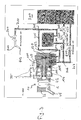
- the figure 9 illustrates an operating phase of the machine during which fluid heated to atmospheric pressure is delivered.
- the discharge solenoid valve 600 is closed (OFF state).
- the pump is activated (ON state), to supply the boiler 500.
- the outlet solenoid valve 800 is open (ON state).
- the heated fluid at the outlet of the boiler 500 can then flow through the outlet branch 710.
- the atmospheric pressure setting of the water of the outlet 712 of the outlet branch 710 prevents a rise in pressure sufficient to push back the tared valve 120.
- the pressure in the hydraulic circuit remains below 3 bars. It is more particularly of the order of 0.5 bar as illustrated on the pressure / flow curve of the figure 9 .
- An increase in the power of the pump 400 would mainly result in an increase in the flow delivered to the outlet 712 without significant increase in the pressure at this outlet 712.
- the calibrated valve 120 therefore blocks the heated water.
- the water is not introduced into the brewing chamber 7.
- the atmospheric pressure setting of the circuit water also prevents a rise in pressure sufficient to push the piston 114.
- the first chamber portion 42 is then not moved.
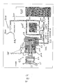
- the figure 10 illustrates the extraction of the infusion system 10 for cleaning and maintenance.
- the separation of the infusion system 10 from the module causes the disconnection of the connection means carried by the module with the complementary connection means carried by the infusion system 10.
- the fingers 112 are disengaged from the non-return valves 61. These then close the passage of the nipples 60. The hydraulic circuit of the module is then blocked.
- the characteristics relating to the output branch for delivering hot water or hot steam at low pressure can be implemented on a machine in which the actuator is supplied with heated fluid.
- the preferred embodiment provides a movable chamber carried by the movable portion of the actuator
- this mobile chamber is not worn by or is not integral with the moving part of the actuator.
- the system is configured so that the forces of the moving part of the actuator are transmitted to the moving chamber portion.
- the movable part of the actuator comes into contact with the movable chamber portion and causes the latter to cause the closure of the brewing chamber.
- the invention also does not preclude providing a complementary device, mechanically operable for example, providing part of the stroke of the movable chamber portion.
- Rear direction 104. feeding channel 20. built 105. passage 22.
Landscapes
- Engineering & Computer Science (AREA)
- Food Science & Technology (AREA)
- Mechanical Engineering (AREA)
- Apparatus For Making Beverages (AREA)
Claims (15)
- Maschine zur Herstellung von Getränken durch Infusion eines aufzugießenden Produkts, umfassend:* ein Infusionssystem (10), umfassend eine Infusionskammer (7), die zur Aufnahme eines aufzugießenden Produkts bestimmt ist,* einen Flüssigkeitskreislauf, umfassend eine Pumpe (400) und einen unterhalb der Pumpe (400) angeordneten Heizkessel (500), den Heizkessel (500) an die Infusionskammer (7) anschließende Versorgungsmittel zur Versorgung der Infusionskammer (7) mit erhitzter Flüssigkeit,* eine tarierte Klappe (120), die zwischen dem Heizkessel (500) und der Infusionskammer (7) angeordnet ist und derart angeordnet ist, dass der Durchfluss der Flüssigkeit zur Infusionskammer (7) verhindert wird, wenn der Druck der Flüssigkeit oberhalb der tarierten Klappe (120) unter einem Infusionsdruck-Schwellenwert liegt und derart, dass der Durchfluss der Flüssigkeit zur Infusionskammer (7) zugelasse wird, wenn der Druck der Flüssigkeit oberhalb der tarierten Klappe (120) höher ist als der genannte Infusionsdruck-Schwellenwert,* einen Abflusszweig (710), umfassend wenigstens einen an einen Ausgang des Heizkessels (500) oder an die Versorgungsmittel oberhalb der tarierten Klappe (120) angeschlossenen Eingang (711) und wenigstens einen Ausgang (712), wobei der Ausgangszweig (710) konfiguriert ist, um das Abfließen der aus dem Heizkessel (500) stammenden Flüssigkeit aus der Maschine zu verhindern,* ein Ausgangsmagnetventil (800), das an dem Ausgangszweig (710) angeordnet ist und dessen Öffnung das Abfließen der Flüssigkeit durch den genannten Ausgang (712) zulässt und dessen Verschluss das Abfließen der Flüssigkeit durch den genannten Ausgang (712) verhindert
dadurch gekennzeichnet, dass sie derart konfiguriert ist, dass die Aktivierung des Ausgangsmagnetventils (800) den Betrieb der Pumpe (400) und den Betrieb des Heizkessels (500) hervorruft. - Maschine gemäß dem voranstehenden Anspruch, die derart konfiguriert ist, dass der Verschluss des Ausgangsmagnetventils (800) den Druckaufbau der Flüssigkeit in dem Flüssigkeitskreislauf derart erlaubt, dass die Öffnung des Ausgangsmagnetventils (800) den Druckaufbau in dem Flüssigkeitskreislauf ermöglicht.
- Maschine gemäß einem der voranstehenden Ansprüche, bei der der Ausgang des Ausgangszweigs (710) mit einer Düse (900) ausgerüstet ist.
- Maschine gemäß einem der voranstehenden Ansprüche, die konfiguriert ist, um die Pumpe (400) intermittierend derart zu aktivieren, dass ein Dampfstrahl am Ausgang (712) des Ausgangszweigs (710) erhalten wird.
- Maschine gemäß einem der voranstehenden Ansprüche, bei der der Eingang des Ausgangszweigs (710) an den Flüssigkeitskreislauf oberhalb des Infusionssystems (10) und unterhalb des Heizkessels (500) angeschlossen ist.
- Maschine gemäß einem der voranstehenden Ansprüche, bei der die Infusionskammer (7) durch wenigstens einen ersten (42) und einen zweiten (22), im Verhältnis zueinander mobilen Abschnitt der Infusionskammer (7) definiert ist, bei der das Infusionssystem (10) ein Stellglied (40) umfasst, das konfiguriert ist, um den ersten (42) und zweiten (22) Abschnitt einander anzunähern oder zu entfernen, um die Infusionskammer (7) jeweils zu schließen oder zu öffnen, und bei der das Stellglied (40) an die Pumpe (400) angeschlossen ist, um mit unter Druck stehender Flüssigkeit versorgt zu werden.
- Maschine gemäß dem voranstehenden Anspruch, die derart konfiguriert ist, dass das Stellglied (40) den Verschluss der Infusionskammer (7) hervorruft, wenn der Druck der das Stellglied (40) versorgenden Flüssigkeit einen Verschlussdruck-Schwellenwert erreicht.
- Maschine gemäß einem der zwei voranstehenden Ansprüche, bei der der Flüssigkeitskreislauf ein Ablass-Magnetventil (600) umfasst, das oberhalb des Stellgliedes (40) angeordnet ist und derart angeordnet ist, dass seine Öffnung das Absenken des Drucks der Flüssigkeit oberhalb des Stellgliedes (40) zulässt.
- Maschine gemäß dem voranstehenden Anspruch, bei der das Ablass-Magnetventil (600) an einen die Pumpe (40) versorgenden Wassertank (200) oder an ein Auffangbecken angeschlossen ist.
- Maschine gemäß einem der voranstehenden Ansprüche, die derart konfiguriert ist, dass das Ausgangs-Magnetventil (800) den Verschluss des Ablass-Magnetventils (600) hervorruft.
- Maschine gemäß einem der voranstehenden Ansprüche, die derart konfiguriert ist, dass ein Druckaufbau der Flüssigkeit in dem Kreislauf verhindert wird, wenn das Ablassventil (600) und / oder das Ausgangs-Magnetventil (800) offen ist und derart, dass der Druckaufbau der Flüssigkeit in dem Kreislauf zugelassen wird, wenn das Ablass-Magnetventil (600) und das Ausgangs-Magnetventil (800) geschlossen sind.
- Maschine gemäß einem der voranstehenden Ansprüche, bei der die Infusionskammer (7) fluidisch an den Heizkessel (500) angeschlossen ist, um erhitzte Flüssigkeit zu erhalten und bei der das Stellglied (40) nicht an den Heizkessel (500) angeschlossen ist und mit nicht erhitzter Flüssigkeit versorgt wird.
- Maschine gemäß einem der voranstehenden Ansprüche, in Verbindung mit Anspruch 7, bei der der erste Abschnitt (42) der Kammer mobil ist und bei der die Infusionskammer (7) durch den ersten Abschnitt der Kammer (42) mit erhitzter Flüssigkeit versorgt wird.
- Maschine gemäß dem voranstehenden Anspruch, bei der der erste Abschnitt (42) der Kammer in Translation mobil ist und bei der der zweite Abschnitt der Kammer (22) fest ist.
- Maschine gemäß einem der acht voranstehenden Ansprüche, bei der das Stellglied ein hydraulischer Antrieb (40) mit einem Zylinder (115) und einem mobilen Kolben (114) im Innern des Zylinders (115) ist, wobei der Zylinder (115) und der Kolben (114) eine durch die Pumpe mit Flüssigkeit versorgte Schubkammer definieren, wobei der Kolben (114) einen Durchgang (105) umfasst, dessen eines Ende unterhalb in fluidischer Verbindung mit der Infusionskammer (7) steht und dessen eines Ende oberhalb in fluidischer Verbindung mit einem Versorgungskanal (104) steht, der dazu bestimmt ist, an den Heizkessel angeschlossen zu werden, und bei dem der Zylinder (115) mit dem Zylinder (115) fest verbundene Aufpressmittel (103) umfasst, die sich in der Schubkammer (100) erstrecken und angepasst sind, um im Innern des Kolbens (114) zu gleiten und den Versorgungskanal (104) aufnehmen.
Applications Claiming Priority (3)
| Application Number | Priority Date | Filing Date | Title |
|---|---|---|---|
| FR1054008 | 2010-05-25 | ||
| FR1054017A FR2960406B1 (fr) | 2010-05-25 | 2010-05-25 | Systeme de production de boissons par infusion |
| PCT/EP2011/058394 WO2011147796A1 (fr) | 2010-05-25 | 2011-05-23 | Systeme de production de boissons par infusion |
Publications (2)
| Publication Number | Publication Date |
|---|---|
| EP2575573A1 EP2575573A1 (de) | 2013-04-10 |
| EP2575573B1 true EP2575573B1 (de) | 2015-07-08 |
Family
ID=45003355
Family Applications (1)
| Application Number | Title | Priority Date | Filing Date |
|---|---|---|---|
| EP11722782.7A Active EP2575573B1 (de) | 2010-05-25 | 2011-05-23 | System zur herstellung von getränken durch infusion |
Country Status (2)
| Country | Link |
|---|---|
| EP (1) | EP2575573B1 (de) |
| WO (1) | WO2011147796A1 (de) |
Cited By (1)
| Publication number | Priority date | Publication date | Assignee | Title |
|---|---|---|---|---|
| WO2018158179A1 (en) * | 2017-02-28 | 2018-09-07 | Nestec Sa | Dispenser with parallel dispensing paths |
Families Citing this family (2)
| Publication number | Priority date | Publication date | Assignee | Title |
|---|---|---|---|---|
| IT201800004243A1 (it) * | 2018-04-05 | 2019-10-05 | Apparecchiatura per la preparazione di bevande calde | |
| IT201900015755A1 (it) | 2019-09-06 | 2021-03-06 | Bruno Bardazzi | Macchina per la preparazione di bevande |
Family Cites Families (3)
| Publication number | Priority date | Publication date | Assignee | Title |
|---|---|---|---|---|
| DK1219217T3 (da) * | 2000-12-29 | 2004-01-05 | Sgl Italia Srl | Kaffemaskine |
| FR2844441B1 (fr) * | 2002-09-16 | 2006-03-31 | Cie Mediterraneenne Des Cafes | Machine pour la production de boisson par infusion d'eau chaude |
| DE502006000132D1 (de) * | 2005-12-02 | 2007-11-22 | Miele & Cie | Verfahren zur Steuerung der Wasserausgabe eines wasserführenden Haushaltsgeräts |
-
2011
- 2011-05-23 EP EP11722782.7A patent/EP2575573B1/de active Active
- 2011-05-23 WO PCT/EP2011/058394 patent/WO2011147796A1/fr not_active Ceased
Cited By (1)
| Publication number | Priority date | Publication date | Assignee | Title |
|---|---|---|---|---|
| WO2018158179A1 (en) * | 2017-02-28 | 2018-09-07 | Nestec Sa | Dispenser with parallel dispensing paths |
Also Published As
| Publication number | Publication date |
|---|---|
| WO2011147796A1 (fr) | 2011-12-01 |
| EP2575573A1 (de) | 2013-04-10 |
Similar Documents
| Publication | Publication Date | Title |
|---|---|---|
| EP1967100B1 (de) | System zur Herstellung eines Getränkes aus einer Kapsel und Verfahren | |
| EP2922447B1 (de) | Vorrichtung zum zubereiten von getränken durch behälterinfusion mit einer schwenkwiege | |
| EP2120654B1 (de) | Verfahren zur herstellung einer infusion | |
| EP2106374B1 (de) | Maschine zur automatischen herstellung und ausgabe von getränken | |
| EP1816937B1 (de) | Braugetränkespender mit verbessertem boiler | |
| EP0484277B1 (de) | Automat zum Bereiten von Kaffeegetränken und Verfahren zur Durchführung dieser Bereitung | |
| EP2575573B1 (de) | System zur herstellung von getränken durch infusion | |
| EP2575560B1 (de) | System zur herstellung von aufgussgetränken | |
| EP2385778B1 (de) | Perkolationsvorrichtung | |
| FR2844441A1 (fr) | Machine pour la production de boisson par infusion d'eau chaude | |
| FR2960406A1 (fr) | Systeme de production de boissons par infusion | |
| EP2476352B1 (de) | Getränkezubereitungsmaschine mit Doppelkammer | |
| EP3027093B1 (de) | System zur herstellung von getränken durch aufgiessen | |
| EP2647318B1 (de) | Ventilvorrichtung für flüssige Lebensmittel, ihr Funktionsverfahren und eine damit ausgestattete Kaffeeausgabemaschine | |
| EP2575565B2 (de) | System zur herstellung von getränken durch infusion | |
| EP1677652B1 (de) | Perfektionierung einer automatischen kaffeemaschine mit einer bewegbaren brühkopfeinheit | |
| EP2185047B1 (de) | Hydraulikkreislauf für eine maschine zur zubereitung von getränken durch aufguss | |
| WO2012056158A1 (fr) | Appareil de confection d'infusions du type a retournement | |
| EP4302658A1 (de) | Optimiertes reinigungsverfahren für eine brühkammer einer kaffeemaschine | |
| FR3077475A1 (fr) | Machine de preparation de boissons munie d'une chaudiere amelioree | |
| FR2966334A1 (fr) | Appareil de confection d'infusions du type a retournement. |
Legal Events
| Date | Code | Title | Description |
|---|---|---|---|
| PUAI | Public reference made under article 153(3) epc to a published international application that has entered the european phase |
Free format text: ORIGINAL CODE: 0009012 |
|
| 17P | Request for examination filed |
Effective date: 20121221 |
|
| AK | Designated contracting states |
Kind code of ref document: A1 Designated state(s): AL AT BE BG CH CY CZ DE DK EE ES FI FR GB GR HR HU IE IS IT LI LT LU LV MC MK MT NL NO PL PT RO RS SE SI SK SM TR |
|
| DAX | Request for extension of the european patent (deleted) | ||
| GRAP | Despatch of communication of intention to grant a patent |
Free format text: ORIGINAL CODE: EPIDOSNIGR1 |
|
| INTG | Intention to grant announced |
Effective date: 20150112 |
|
| GRAS | Grant fee paid |
Free format text: ORIGINAL CODE: EPIDOSNIGR3 |
|
| GRAA | (expected) grant |
Free format text: ORIGINAL CODE: 0009210 |
|
| AK | Designated contracting states |
Kind code of ref document: B1 Designated state(s): AL AT BE BG CH CY CZ DE DK EE ES FI FR GB GR HR HU IE IS IT LI LT LU LV MC MK MT NL NO PL PT RO RS SE SI SK SM TR |
|
| REG | Reference to a national code |
Ref country code: GB Ref legal event code: FG4D Free format text: NOT ENGLISH |
|
| REG | Reference to a national code |
Ref country code: AT Ref legal event code: REF Ref document number: 734695 Country of ref document: AT Kind code of ref document: T Effective date: 20150715 Ref country code: CH Ref legal event code: EP |
|
| REG | Reference to a national code |
Ref country code: IE Ref legal event code: FG4D Free format text: LANGUAGE OF EP DOCUMENT: FRENCH |
|
| REG | Reference to a national code |
Ref country code: DE Ref legal event code: R096 Ref document number: 602011017687 Country of ref document: DE |
|
| REG | Reference to a national code |
Ref country code: AT Ref legal event code: MK05 Ref document number: 734695 Country of ref document: AT Kind code of ref document: T Effective date: 20150708 |
|
| REG | Reference to a national code |
Ref country code: NL Ref legal event code: MP Effective date: 20150708 |
|
| REG | Reference to a national code |
Ref country code: LT Ref legal event code: MG4D |
|
| PG25 | Lapsed in a contracting state [announced via postgrant information from national office to epo] |
Ref country code: LT Free format text: LAPSE BECAUSE OF FAILURE TO SUBMIT A TRANSLATION OF THE DESCRIPTION OR TO PAY THE FEE WITHIN THE PRESCRIBED TIME-LIMIT Effective date: 20150708 Ref country code: GR Free format text: LAPSE BECAUSE OF FAILURE TO SUBMIT A TRANSLATION OF THE DESCRIPTION OR TO PAY THE FEE WITHIN THE PRESCRIBED TIME-LIMIT Effective date: 20151009 Ref country code: FI Free format text: LAPSE BECAUSE OF FAILURE TO SUBMIT A TRANSLATION OF THE DESCRIPTION OR TO PAY THE FEE WITHIN THE PRESCRIBED TIME-LIMIT Effective date: 20150708 Ref country code: NO Free format text: LAPSE BECAUSE OF FAILURE TO SUBMIT A TRANSLATION OF THE DESCRIPTION OR TO PAY THE FEE WITHIN THE PRESCRIBED TIME-LIMIT Effective date: 20151008 Ref country code: LV Free format text: LAPSE BECAUSE OF FAILURE TO SUBMIT A TRANSLATION OF THE DESCRIPTION OR TO PAY THE FEE WITHIN THE PRESCRIBED TIME-LIMIT Effective date: 20150708 |
|
| PG25 | Lapsed in a contracting state [announced via postgrant information from national office to epo] |
Ref country code: SE Free format text: LAPSE BECAUSE OF FAILURE TO SUBMIT A TRANSLATION OF THE DESCRIPTION OR TO PAY THE FEE WITHIN THE PRESCRIBED TIME-LIMIT Effective date: 20150708 Ref country code: ES Free format text: LAPSE BECAUSE OF FAILURE TO SUBMIT A TRANSLATION OF THE DESCRIPTION OR TO PAY THE FEE WITHIN THE PRESCRIBED TIME-LIMIT Effective date: 20150708 Ref country code: RS Free format text: LAPSE BECAUSE OF FAILURE TO SUBMIT A TRANSLATION OF THE DESCRIPTION OR TO PAY THE FEE WITHIN THE PRESCRIBED TIME-LIMIT Effective date: 20150708 Ref country code: PL Free format text: LAPSE BECAUSE OF FAILURE TO SUBMIT A TRANSLATION OF THE DESCRIPTION OR TO PAY THE FEE WITHIN THE PRESCRIBED TIME-LIMIT Effective date: 20150708 Ref country code: AT Free format text: LAPSE BECAUSE OF FAILURE TO SUBMIT A TRANSLATION OF THE DESCRIPTION OR TO PAY THE FEE WITHIN THE PRESCRIBED TIME-LIMIT Effective date: 20150708 Ref country code: IS Free format text: LAPSE BECAUSE OF FAILURE TO SUBMIT A TRANSLATION OF THE DESCRIPTION OR TO PAY THE FEE WITHIN THE PRESCRIBED TIME-LIMIT Effective date: 20151108 Ref country code: PT Free format text: LAPSE BECAUSE OF FAILURE TO SUBMIT A TRANSLATION OF THE DESCRIPTION OR TO PAY THE FEE WITHIN THE PRESCRIBED TIME-LIMIT Effective date: 20151109 Ref country code: HR Free format text: LAPSE BECAUSE OF FAILURE TO SUBMIT A TRANSLATION OF THE DESCRIPTION OR TO PAY THE FEE WITHIN THE PRESCRIBED TIME-LIMIT Effective date: 20150708 |
|
| REG | Reference to a national code |
Ref country code: CH Ref legal event code: NV Representative=s name: P&TS SA, CH |
|
| REG | Reference to a national code |
Ref country code: DE Ref legal event code: R097 Ref document number: 602011017687 Country of ref document: DE |
|
| PG25 | Lapsed in a contracting state [announced via postgrant information from national office to epo] |
Ref country code: IT Free format text: LAPSE BECAUSE OF FAILURE TO SUBMIT A TRANSLATION OF THE DESCRIPTION OR TO PAY THE FEE WITHIN THE PRESCRIBED TIME-LIMIT Effective date: 20150708 Ref country code: EE Free format text: LAPSE BECAUSE OF FAILURE TO SUBMIT A TRANSLATION OF THE DESCRIPTION OR TO PAY THE FEE WITHIN THE PRESCRIBED TIME-LIMIT Effective date: 20150708 Ref country code: DK Free format text: LAPSE BECAUSE OF FAILURE TO SUBMIT A TRANSLATION OF THE DESCRIPTION OR TO PAY THE FEE WITHIN THE PRESCRIBED TIME-LIMIT Effective date: 20150708 Ref country code: CZ Free format text: LAPSE BECAUSE OF FAILURE TO SUBMIT A TRANSLATION OF THE DESCRIPTION OR TO PAY THE FEE WITHIN THE PRESCRIBED TIME-LIMIT Effective date: 20150708 Ref country code: SK Free format text: LAPSE BECAUSE OF FAILURE TO SUBMIT A TRANSLATION OF THE DESCRIPTION OR TO PAY THE FEE WITHIN THE PRESCRIBED TIME-LIMIT Effective date: 20150708 |
|
| PLBE | No opposition filed within time limit |
Free format text: ORIGINAL CODE: 0009261 |
|
| STAA | Information on the status of an ep patent application or granted ep patent |
Free format text: STATUS: NO OPPOSITION FILED WITHIN TIME LIMIT |
|
| REG | Reference to a national code |
Ref country code: FR Ref legal event code: PLFP Year of fee payment: 6 |
|
| PG25 | Lapsed in a contracting state [announced via postgrant information from national office to epo] |
Ref country code: RO Free format text: LAPSE BECAUSE OF FAILURE TO SUBMIT A TRANSLATION OF THE DESCRIPTION OR TO PAY THE FEE WITHIN THE PRESCRIBED TIME-LIMIT Effective date: 20150708 |
|
| 26N | No opposition filed |
Effective date: 20160411 |
|
| PG25 | Lapsed in a contracting state [announced via postgrant information from national office to epo] |
Ref country code: SI Free format text: LAPSE BECAUSE OF FAILURE TO SUBMIT A TRANSLATION OF THE DESCRIPTION OR TO PAY THE FEE WITHIN THE PRESCRIBED TIME-LIMIT Effective date: 20150708 |
|
| REG | Reference to a national code |
Ref country code: IE Ref legal event code: MM4A |
|
| PG25 | Lapsed in a contracting state [announced via postgrant information from national office to epo] |
Ref country code: IE Free format text: LAPSE BECAUSE OF NON-PAYMENT OF DUE FEES Effective date: 20160523 |
|
| REG | Reference to a national code |
Ref country code: FR Ref legal event code: PLFP Year of fee payment: 7 |
|
| PG25 | Lapsed in a contracting state [announced via postgrant information from national office to epo] |
Ref country code: NL Free format text: LAPSE BECAUSE OF FAILURE TO SUBMIT A TRANSLATION OF THE DESCRIPTION OR TO PAY THE FEE WITHIN THE PRESCRIBED TIME-LIMIT Effective date: 20150708 |
|
| REG | Reference to a national code |
Ref country code: FR Ref legal event code: PLFP Year of fee payment: 8 |
|
| PG25 | Lapsed in a contracting state [announced via postgrant information from national office to epo] |
Ref country code: CY Free format text: LAPSE BECAUSE OF FAILURE TO SUBMIT A TRANSLATION OF THE DESCRIPTION OR TO PAY THE FEE WITHIN THE PRESCRIBED TIME-LIMIT Effective date: 20150708 Ref country code: SM Free format text: LAPSE BECAUSE OF FAILURE TO SUBMIT A TRANSLATION OF THE DESCRIPTION OR TO PAY THE FEE WITHIN THE PRESCRIBED TIME-LIMIT Effective date: 20150708 Ref country code: HU Free format text: LAPSE BECAUSE OF FAILURE TO SUBMIT A TRANSLATION OF THE DESCRIPTION OR TO PAY THE FEE WITHIN THE PRESCRIBED TIME-LIMIT; INVALID AB INITIO Effective date: 20110523 |
|
| PG25 | Lapsed in a contracting state [announced via postgrant information from national office to epo] |
Ref country code: TR Free format text: LAPSE BECAUSE OF FAILURE TO SUBMIT A TRANSLATION OF THE DESCRIPTION OR TO PAY THE FEE WITHIN THE PRESCRIBED TIME-LIMIT Effective date: 20150708 Ref country code: MT Free format text: LAPSE BECAUSE OF FAILURE TO SUBMIT A TRANSLATION OF THE DESCRIPTION OR TO PAY THE FEE WITHIN THE PRESCRIBED TIME-LIMIT Effective date: 20150708 Ref country code: MK Free format text: LAPSE BECAUSE OF FAILURE TO SUBMIT A TRANSLATION OF THE DESCRIPTION OR TO PAY THE FEE WITHIN THE PRESCRIBED TIME-LIMIT Effective date: 20150708 |
|
| PG25 | Lapsed in a contracting state [announced via postgrant information from national office to epo] |
Ref country code: BG Free format text: LAPSE BECAUSE OF FAILURE TO SUBMIT A TRANSLATION OF THE DESCRIPTION OR TO PAY THE FEE WITHIN THE PRESCRIBED TIME-LIMIT Effective date: 20150708 |
|
| PG25 | Lapsed in a contracting state [announced via postgrant information from national office to epo] |
Ref country code: AL Free format text: LAPSE BECAUSE OF FAILURE TO SUBMIT A TRANSLATION OF THE DESCRIPTION OR TO PAY THE FEE WITHIN THE PRESCRIBED TIME-LIMIT Effective date: 20150708 |
|
| PGFP | Annual fee paid to national office [announced via postgrant information from national office to epo] |
Ref country code: MC Payment date: 20200529 Year of fee payment: 10 Ref country code: LU Payment date: 20200417 Year of fee payment: 10 Ref country code: DE Payment date: 20200513 Year of fee payment: 10 |
|
| PGFP | Annual fee paid to national office [announced via postgrant information from national office to epo] |
Ref country code: BE Payment date: 20200519 Year of fee payment: 10 Ref country code: GB Payment date: 20200527 Year of fee payment: 10 |
|
| REG | Reference to a national code |
Ref country code: DE Ref legal event code: R119 Ref document number: 602011017687 Country of ref document: DE |
|
| GBPC | Gb: european patent ceased through non-payment of renewal fee |
Effective date: 20210523 |
|
| PG25 | Lapsed in a contracting state [announced via postgrant information from national office to epo] |
Ref country code: MC Free format text: LAPSE BECAUSE OF NON-PAYMENT OF DUE FEES Effective date: 20210531 Ref country code: LU Free format text: LAPSE BECAUSE OF NON-PAYMENT OF DUE FEES Effective date: 20210523 |
|
| REG | Reference to a national code |
Ref country code: BE Ref legal event code: MM Effective date: 20210531 |
|
| PG25 | Lapsed in a contracting state [announced via postgrant information from national office to epo] |
Ref country code: GB Free format text: LAPSE BECAUSE OF NON-PAYMENT OF DUE FEES Effective date: 20210523 Ref country code: DE Free format text: LAPSE BECAUSE OF NON-PAYMENT OF DUE FEES Effective date: 20211201 |
|
| PG25 | Lapsed in a contracting state [announced via postgrant information from national office to epo] |
Ref country code: BE Free format text: LAPSE BECAUSE OF NON-PAYMENT OF DUE FEES Effective date: 20210531 |
|
| P01 | Opt-out of the competence of the unified patent court (upc) registered |
Effective date: 20230601 |
|
| PGFP | Annual fee paid to national office [announced via postgrant information from national office to epo] |
Ref country code: FR Payment date: 20250526 Year of fee payment: 15 |
|
| PGFP | Annual fee paid to national office [announced via postgrant information from national office to epo] |
Ref country code: CH Payment date: 20250601 Year of fee payment: 15 |