EP1545134B1 - Méthode et appareil pour réduire les artefacts MPEG - Google Patents
Méthode et appareil pour réduire les artefacts MPEG Download PDFInfo
- Publication number
- EP1545134B1 EP1545134B1 EP04257653A EP04257653A EP1545134B1 EP 1545134 B1 EP1545134 B1 EP 1545134B1 EP 04257653 A EP04257653 A EP 04257653A EP 04257653 A EP04257653 A EP 04257653A EP 1545134 B1 EP1545134 B1 EP 1545134B1
- Authority
- EP
- European Patent Office
- Prior art keywords
- pixel value
- window
- value
- pixel
- differences
- Prior art date
- Legal status (The legal status is an assumption and is not a legal conclusion. Google has not performed a legal analysis and makes no representation as to the accuracy of the status listed.)
- Active
Links
Images


Classifications
-
- H—ELECTRICITY
- H04—ELECTRIC COMMUNICATION TECHNIQUE
- H04N—PICTORIAL COMMUNICATION, e.g. TELEVISION
- H04N19/00—Methods or arrangements for coding, decoding, compressing or decompressing digital video signals
- H04N19/85—Methods or arrangements for coding, decoding, compressing or decompressing digital video signals using pre-processing or post-processing specially adapted for video compression
-
- H—ELECTRICITY
- H04—ELECTRIC COMMUNICATION TECHNIQUE
- H04N—PICTORIAL COMMUNICATION, e.g. TELEVISION
- H04N19/00—Methods or arrangements for coding, decoding, compressing or decompressing digital video signals
- H04N19/50—Methods or arrangements for coding, decoding, compressing or decompressing digital video signals using predictive coding
- H04N19/503—Methods or arrangements for coding, decoding, compressing or decompressing digital video signals using predictive coding involving temporal prediction
- H04N19/51—Motion estimation or motion compensation
- H04N19/527—Global motion vector estimation
-
- H—ELECTRICITY
- H04—ELECTRIC COMMUNICATION TECHNIQUE
- H04N—PICTORIAL COMMUNICATION, e.g. TELEVISION
- H04N19/00—Methods or arrangements for coding, decoding, compressing or decompressing digital video signals
- H04N19/10—Methods or arrangements for coding, decoding, compressing or decompressing digital video signals using adaptive coding
- H04N19/102—Methods or arrangements for coding, decoding, compressing or decompressing digital video signals using adaptive coding characterised by the element, parameter or selection affected or controlled by the adaptive coding
- H04N19/117—Filters, e.g. for pre-processing or post-processing
-
- H—ELECTRICITY
- H04—ELECTRIC COMMUNICATION TECHNIQUE
- H04N—PICTORIAL COMMUNICATION, e.g. TELEVISION
- H04N19/00—Methods or arrangements for coding, decoding, compressing or decompressing digital video signals
- H04N19/10—Methods or arrangements for coding, decoding, compressing or decompressing digital video signals using adaptive coding
- H04N19/134—Methods or arrangements for coding, decoding, compressing or decompressing digital video signals using adaptive coding characterised by the element, parameter or criterion affecting or controlling the adaptive coding
- H04N19/136—Incoming video signal characteristics or properties
- H04N19/14—Coding unit complexity, e.g. amount of activity or edge presence estimation
-
- H—ELECTRICITY
- H04—ELECTRIC COMMUNICATION TECHNIQUE
- H04N—PICTORIAL COMMUNICATION, e.g. TELEVISION
- H04N19/00—Methods or arrangements for coding, decoding, compressing or decompressing digital video signals
- H04N19/10—Methods or arrangements for coding, decoding, compressing or decompressing digital video signals using adaptive coding
- H04N19/169—Methods or arrangements for coding, decoding, compressing or decompressing digital video signals using adaptive coding characterised by the coding unit, i.e. the structural portion or semantic portion of the video signal being the object or the subject of the adaptive coding
- H04N19/17—Methods or arrangements for coding, decoding, compressing or decompressing digital video signals using adaptive coding characterised by the coding unit, i.e. the structural portion or semantic portion of the video signal being the object or the subject of the adaptive coding the unit being an image region, e.g. an object
- H04N19/176—Methods or arrangements for coding, decoding, compressing or decompressing digital video signals using adaptive coding characterised by the coding unit, i.e. the structural portion or semantic portion of the video signal being the object or the subject of the adaptive coding the unit being an image region, e.g. an object the region being a block, e.g. a macroblock
-
- H—ELECTRICITY
- H04—ELECTRIC COMMUNICATION TECHNIQUE
- H04N—PICTORIAL COMMUNICATION, e.g. TELEVISION
- H04N19/00—Methods or arrangements for coding, decoding, compressing or decompressing digital video signals
- H04N19/60—Methods or arrangements for coding, decoding, compressing or decompressing digital video signals using transform coding
- H04N19/61—Methods or arrangements for coding, decoding, compressing or decompressing digital video signals using transform coding in combination with predictive coding
Definitions
- This invention generally relates to improving video and graphics quality.
- MPEG compression is a widely used algorithm for digital video signal transmission and storage.
- MPEG encoded and decoded streams of video can be used in various applications including cable television, satellite television, and digital video discs (DVD).
- DVD digital video discs
- the content of a video signal generally comprises a sequence of image frames for a progressive video sequence and image fields for an interlaced video sequence. Each frame/field consists of a rectangular spatial area of pixels.
- an 8X8 window of pixels (64 pixels) in an image frame of the video signal is processed as follows. First, a Discrete Cosine Transform (DCT) is applied to the window to generate a 2-D spatial spectrum representation of the 8X8 window.
- DCT Discrete Cosine Transform
- This 2-D spatial spectrum is often referred to as a Fourier image, as it is a representation of the image in the Fourier domain.
- the Fourier image also has 64 pixels.
- the pixel values in the Fourier image represent a DC component and various frequencies or AC components.
- the DC component is generally situated in a top left corner pixel of the Fourier image.
- the other 63 pixels in the Fourier image represent the AC components.
- an MPEG encoder quantization is applied so that all the 64 pixels in the Fourier image are quantized.
- the MPEG-2 standard provides for intraframe compression.
- neighboring image frames are grouped into one or more Groups of Pictures ("GOP").
- GOP Groups of Pictures
- one image frame is encoded spatially, namely the I-frame.
- differences are encoded.
- P-frame the difference between a current frame and a modified by motion vectors I-frame is spatially encoded.
- B-frame the difference between a current frame and a weighting sum of a modified by motion vectors I-frame and P-frame or two P-frames is spatially encoded.
- Modified by motion vectors means that the currently encoded P- (or B-) frame is split by 16x16 pixel squares, and for each square the best matched square located with some spatial offset from the reference frame is searched. The searching happens in some local area. The spatial offset (vertical and horizontal) for the best matching block is kept in the MPEG stream and called the motion vector. Each 16x16 block of P-frame has one motion vector, and the B-frame has two motion vectors. MPEG compression for an interlaced signal processes fields instead of frames.
- the image frame is converted back from the Fourier domain to the spatial domain.
- the encoding and decoding of image frames using MPEG compression causes artifacts to appear in a processed image frame.
- the compression ratio, i.e. bit rate used in the MPEG encoding and decoding defines the level and behavior of the artifacts. That is, the visually perceived effect of the artifacts is a function of the bit rate.
- edge (line) areas blocking artifacts are caused by transitions between neighboring windows or blocks in the presence of natural edges and lines, for instance, tree branches, wires, or edges between objects. In these edge areas, additional jaggedness is visually perceived.
- Increasing the bit rate to an intermediate or high level, for instance, higher than 2 Mbits/sec, can effectively reduce blocking artifacts occurring at low bit rates.
- other artifacts such as mosquito noise, and flat area blocking artifact, can also take place.
- mosquito noise is a high frequency pattern that appears inside a window or block of pixels particularly in a more or less flat area in the presence of a high edge in a neighborhood or any other high transition between pixel values.
- the mosquito noise appears as a small checkerboard mixed with delta-impulse pattern that is clearly visible in areas within the window.
- Mosquito noise becomes visible due to the uniform spatial distribution of quantization noise appearing in blocks which contain generally smooth areas in the presence of strong edges.
- the mosquito noise is perceptually visible in the smooth areas. Pure vertical and horizontal intrablock ringing is one type of the mosquito noise.
- mosquito noise appears close to vertical and horizontal edges in the image frame.
- the mosquito noise caused by pure vertical or horizontal edges is less severe than that caused by diagonal structures, but is still visible as vertical and horizontal ringing of the edges.
- a flat area (DC) blocking artifact is perceptually visible at intermediate and high bit rates (greater than about 2 Mbits/sec).
- the flat area blocking artifact is caused by the quantized block essentially containing only one DC component, i.e. values of the pixels of the decoded block are the same.
- the smooth flat area appears as tiled 8x8 squares having close but different values.
- the video signal maybe digital or analog, and it could be transmitted from a DVD player, cable television source, satellite, or a montage of images from different sources.
- the video signal may be a combination from several analog and digital sources.
- any technique for artifacts reduction needs to perform effectively independent of any knowledge about the source of the video signal, including any knowledge about window or block boundaries in an image frame or video signal.
- Such knowledge might include information about edges, texture information and other information. If such knowledge was required, MPEG artifacts reduction techniques would be unnecessarily complex and hardware and time consuming.
- Video sequences can also be affected by channel additive Gaussian Noise independent from MPEG artifacts.
- EP-A2-0772365 describes a method of filtering a picture signal and encoding/decoding using the same to decrease a step (i.e. block distortion) on a block boundary.
- a window of the image frame is provided.
- the window includes a plurality of pixel values.
- One of the pixel values is selected from the pixel values in the window to define a modified window of pixel value differences.
- a local mean (DC) value is computed based on the pixel value differences.
- a mosquito noise reduction value is also computed based on the pixel value differences.
- An artifact attenuation factor is computed as a function of a dynamic range measure of the pixel value differences.
- a weighted sum of the mosquito noise reduction value and the local mean value, applying the artifact attenuation factor, and the selected pixel value is computed to generate a modified pixel value.
- Embodiments of the present invention provide methods, apparatus, including computer program products, for modifying pixel values in an image frame of a video signal to reduce artifacts in the image frame.
- the methods and apparatus described herein are generally performed in the context of MPEG compression in which intermediate and high bit rates are used, generally above 2 Mbits/sec. These techniques are particularly well suited for removing mosquito noise, including pure vertical and horizontal intrablock ringing, and flat area (DC) blocking artifacts.
- Embodiments of the invention provide methods and apparatus, including computer program products, implementing and using techniques for modifying pixel values of an image frame of a video signal to reduce artifacts in the image frame.
- an input image frame is received and processed pixel by pixel by one or more of several modules to reduce the above-described artifacts in the image frame.
- the modules cooperate to correct pixel values of the image frame so that the artifacts are reduced while preserving the natural details of the image frame as much as possible.
- Embodiments of methods and apparatus disclosed herein process, pixel by pixel, a square sliding window as a processing aperture wherein the modifying pixel is generally a central pixel of the window.
- This window includes a plurality of pixel values.
- the size of the sliding window is preferably small, e.g. 3x3.
- a nxn window is used, where n is a small odd value.
- the goal is to modify the pixel value located at the center of the window to reduce artifacts.
- the central pixel value is subtracted from the pixel values in the window to define a modified window of pixel value differences. The central pixel difference is zero.
- a mosquito noise reduction module is provided to identify the mosquito noise component of a pixel.
- the mosquito noise reduction processing is based on knowledge that mosquito noise has high frequency patterns in vertical and horizontal directions, and assumes that its dynamic range is limited to the value defined by a threshold.
- the mosquito noise reduction module performs a mosquito noise reduction operation on the pixel value differences in the modified window to generate two signals.
- First is a mosquito noise reduction value.
- Second is a local DC value based on the sliding window aperture.
- a nonlinear function is applied to the difference between the mosquito noise reduction value and the local DC value.
- the nonlinear processing module reduces residual noise, pure vertical and horizontal ringing, DC blocking artifacts, and residual mosquito noise remaining in the pixel after processing by the mosquito noise reduction module.
- the nonlinear processing module has an adaptive threshold and operates to essentially force the value computed by the mosquito noise reduction module towards a local DC value, using techniques explained below.
- the nonlinear processing module effectively reduces pure vertical and horizontal ringing and DC blocking artifacts without introducing much blur into the image.
- the output value of the nonlinear processing module is multiplied by a static blurriness parameter ⁇ to control the overall blurriness of the image details.
- the product is multiplied by a Gaussian Noise attenuation factor generated by a smooth attenuation module, described below, and controls the Gaussian Noise reduction strength.
- This product is added back to the local DC value, since the local DC value was subtracted in the nonlinear processing module.
- the result is multiplied by an MPEG artifact attenuation factor, also generated by the smooth attenuation module, and controls the MPEG artifact reduction strength.
- the result of the multiplication is added to the aperture window central pixel input value, since the central pixel value was subtracted from the pixel values of the sliding window. This value is the output of the MPEG artifact reduction method and apparatus, according to some embodiments of the present invention.
- the smooth attenuation module is provided to generate the MPEG artifact attenuation factor and Gaussian Noise attenuation factor based on MPEG artifact and Gaussian Noise reducing dynamic ranges. These dynamic ranges are defined by an MPEG artifact threshold and a Gaussian Noise threshold.
- the attenuation factors have three working zones: maximum value, zero and smooth transition between maximum and zero. The absence of the smooth transition zone can provide additional flickering. The flickering happens because values of pixels may change from frame-to-frame from slightly below the threshold to slightly above it, and the hard switch from zero to maximum takes place. Small changes up and down cause big changes up and down.
- the smooth attenuation module outputs attenuation factors having these zones, and additional flickering does not take place.
- Embodiments of the methods and apparatus disclosed herein provide for a spatial method, which is generally practiced in a two-dimensional area or window representing part of an image frame in a video signal. This frame is generally processed on a pixel-by-pixel basis.
- Embodiments of the methods and apparatus described herein can be implemented in various combinations of software and hardware.
- the methods and apparatus are implemented in a video controller for use with a television or other display device.
- the methods and apparatus described herein are particularly well suited for processing video signals from any of various sources, including analog sources, digital sources, and a montage of analog and digital signals.
- the methods and apparatus are applicable to TV sets, DVD players, cable television systems, and satellite transmission of television signals.
- Artifacts associated with intermediate and high bit rates encoding, including mosquito noise and flat area blocking artifacts, are reduced regardless of the source of the video signal. No knowledge of window or block boundaries used in MPEG compression is required.
- embodiments of the methods and apparatus are computationally less complex, less time consuming, and less hardware consuming than conventional techniques requiring knowledge of block boundaries.
- Fig. 1 shows an apparatus 100 for modifying a pixel value in an image frame of an input video signal to reduce artifacts in the image frame.
- the apparatus 100 includes a windowing and pixel subtraction module 105 which receives an input image frame.
- the apparatus 100 further includes a mosquito noise reduction and local mean determination module 110 which receives pixel values a'-i' from windowing and pixel subtraction module 105.
- apparatus 100 includes nonlinear processing module 115 which receives information from mosquito noise reduction and local mean determination module 110 and outputs a value to a multiplier module 130 to be multiplied by a static blurriness parameter ⁇ .
- the apparatus 100 also includes smooth attenuation module 120, which receives pixel values a' - i' from module 105 and outputs MPEG artifact and Gaussian Noise attenuation factors ⁇ and ⁇ 1 to an output module 125.
- Output module 125 which receives output values from module 130 and module 120 and the local DC value from module 110 provides a modified pixel value e as output.
- windowing and pixel subtraction module 105 outputs central pixel value "e" to output module 125 for modification of that pixel value "e.”
- Parameters T 2 , T 1 , T 0 , and ⁇ are control parameters for the method 200 and apparatus 100, and are discussed below.
- Fig. 2 provides a method 200 of the operation of the apparatus 100 for modifying a pixel value in an image frame to reduce artifacts in the image frame.
- the input image frame is provided to windowing and pixel subtraction module 105.
- windowing and pixel subtraction module 105 provides two functions: (1) a sliding windowing operation, and (2) a pixel subtraction operation.
- there is a separate module for each function that is, the windowing operation is provided by a windowing module, and the pixel subtraction operation is performed by a separate pixel subtraction module.
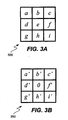
- windowing module 105 provides a window 300 of the input image frame.
- window 300 is a 3x3 sliding window described below with reference to Fig. 3A .
- the window includes a plurality of pixel values from a portion of the input image frame.
- the pixel subtraction module in module 105 subtracts a central pixel value in the window from the other pixel values in the window to define a modified window of pixel value differences a'-i', as described below with reference to Fig. 3B .
- mosquito noise reduction and local mean determination module 110 provides two functions: (1) a mosquito noise reduction operation, and (2) a local mean determination operation.
- the local mean determination module is a submodule of mosquito noise reduction module.
- the local mean determination module determines a local mean value "E DC " based on the input pixel value differences a'-i'.
- the mosquito noise reduction module 110 performs a mosquito reduction operation on the pixel value differences a'-i' in the modified window of Fig. 3B to generate a mosquito noise reduction value "u.” This mosquito noise reduction operation is described below with respect to Figs. 4 and 5 .
- nonlinear processing module 115 determines the difference between local mean value "E DC " and mosquito noise reduction value "u” and generates a nonlinear function based on this difference to reduce the DC blocking artifact, and pure vertical and horizontal ringing.
- step 235 of Fig. 2 the value output from nonlinear processing module 115 is multiplied in multiplier block 130 by a blurriness parameter ⁇ which controls overall blurriness. The output result is received by module 125.
- step 240 the processing in the output module 125 takes place.
- the input value 134 is multiplied by Gaussian Noise attenuation factor ⁇ 1 received from smooth attenuation module 120.
- the local mean received from module 110 is added to the product.
- the result is multiplied by MPEG artifact attenuation factor ⁇ , also received from the smooth attenuation module 120.
- the obtained product is added to the central pixel value of the sliding window received from the module 105 and outputs a modified pixel value e ⁇ .
- the attenuation factors ⁇ and ⁇ 1 provided to the output module 125 control the strength of the MPEG artifact and Gaussian Noise reduction done by previous modules to the pixel value e.
- the modified pixel value e is allocated in the output image frame.
- Fig. 3A shows an illustration of a window 300 of pixel values a-i in the input image frame provided to windowing and pixel subtraction module 105 of Fig. 1 .
- window 300 is a 3X3 window of pixels from the input image frame.
- nxn where n is preferably a small odd number
- a central pixel "e" of the 3X3 window is selected as the pixel for processing.
- the sliding window 300 is moved along the entire image frame in both horizontal and vertical directions, i.e. pixel by pixel in each line, line by line, to process all of the pixels in the image frame.
- the window 300 enables apparatus 100 to provide a modification of the central pixel value "e" based on the 9 pixel values a-i in the window 300.
- Fig. 3B shows a modified window 350 of pixel value differences a'-i' after the pixel subtraction operation 215 is performed on window 300 by module 105 in Fig. 1 .
- the central pixel "e" is subtracted from each pixel a-i in window 300 to define pixel value differences a'-i' as shown in Fig. 3B .
- Fig. 4 shows a block diagram of mosquito noise reduction and local mean determination module 110 constructed according to one embodiment of the present invention.
- the module 110 includes limiting modules 405, local mean determination module 410, 2D - highpass filter 415, and a variance module 420 for computing a weighting coefficient ⁇ .
- Fig. 5 provides a flow diagram of a method 500 for performing a mosquito noise reduction operation, described with reference to Fig. 4 .
- the mosquito noise reduction and local mean determination module 110 decreases intrablock ringing while preserving as much as possible the natural details of the input image frame.
- the mosquito noise reduction operation is based on knowledge that mosquito noise is a high frequency process both in vertical and horizontal directions, appears as a mixture of checkerboard and delta-impulse patterns, and the assumption that the mosquito noise dynamic range is located in the range of e - T 1 to e + T 1 .
- pixel value differences a'-i' of modified window 350 are provided to the limiting modules 405.
- the limiting modules 405 limit the pixel value differences by a threshold - T 1 from the bottom and + T 1 from the top to define limited pixel value differences.
- This threshold T 1 defines the working dynamic range for mosquito noise reduction.
- the limiting modules output a group of the limited pixel value differences, b", d", f", h", a", c", g", and i".
- a ⁇ Lim a ⁇ T 1
- b ⁇ Lim b ⁇ T 1
- c ⁇ Lim c ⁇ T 1
- d ⁇ Lim d ⁇ T 1
- f ⁇ Lim f ⁇ T 1
- g ⁇ Lim g ⁇ T 1
- h ⁇ Lim h ⁇ T 1
- i ⁇ Lim i ⁇ T 1
- Lim x T 1 ⁇ x , x ⁇ T 1 sign x ⁇ T 1 , x > T 1 .
- step 510 the 2D - highpass filter 415 computes a reducing value of the checkerboard pattern E cb .
- step 511 local mean determination module 410 computes the local DC value E DC .
- variance module 420 of Fig. 4 computes a weighting coefficient ⁇ as a function of a variance of the limited pixel value differences a"-i".
- the weighting coefficient ⁇ is provided to a summing module 425, along with the reducing value of the checkerboard pattern E cb and local DC value E DC to compute a weighted sum to generate a mosquito noise reduction value "u.”
- u ⁇ ⁇ E cb + 1 - a ⁇ E DC ,
- ⁇ generated by variance module 420 desirably satisfies the condition 0 ⁇ ⁇ ⁇ 1 and depends on the closeness of the pixels surrounding the center pixel e to each other.
- ⁇ 1 is a predetermined constant positive value, obtained on the basis of subjective experimentation.
- ⁇ 1 5 was chosen. Decreasing ⁇ 1 , it is possible to reduce artifacts with more blurring of natural details of the image.
- local mean determination module 410 includes a two-dimensional lowpass filter for local mean determination, for a 3x3 window obtained from the one-dimensional filter: 1/4 1/2 1/4 having the following impulse response: 1/16 1/8 1/16 1/8 1/4 1/8 1/16 1/8 1/16.
- a two-dimensional highpass filter for the reducing value of the checkerboard pattern E cb. for a 3x3 window obtained from the one-dimensional filter: -1/4 1/2 -1/4 has the following impulse response: -1/16 1/8 -1/16 1/8 1/4 1/8 -1/16 1/8 -1/16.
- the E DC value is output to nonlinear processing module 115 along with the mosquito noise reduction value u, as shown in Fig. 1 .
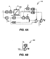
- the nonlinear processing module 115 of Figs. 1 and 6A, 6B reduces any residual amounts of mosquito noise remaining after the mosquito noise reduction operation is performed, as well as DC blocking artifacts and pure vertical or horizontal ringing.
- the nonlinear processing module 115 essentially forces the modified pixel value towards the local DC value E DC to reduce remaining high frequency components associated with mosquito noise, DC blocking artifacts and pure vertical or horizontal ringing.
- Fig. 6B shows a limitation module 650 of nonlinear processing module 115, according to one embodiment of the present invention.
- Fig. 6C provides a flow diagram of a method 600 for performing a nonlinear processing operation, described with reference to Fig. 6A .
- a dynamic dead zone threshold T DC is computed based on: (1) a DC blocking artifact threshold, To, also referred to as a static dead zone threshold, and (2) the input mosquito noise reduction value.
- a nonlinear function ⁇ ( ⁇ ) is applied, forcing the input value to or toward zero.
- FIG. 7 A graphical illustration of the exemplary nonlinear function ⁇ ( ⁇ ) 700 applied by nonlinear processing module 115 is shown in Fig. 7 .
- the nonlinear function above avoids hard thresholding at T DC , as shown in Fig. 7 . Thresholding can cause flickering.
- the nonlinear function has a linear transition between T DC and 2T DC instead of a hard switch, helping to reduce any such flickering.
- the control parameter To is a predetermined threshold, defining a static dead zone of the nonlinear function.
- the value of the threshold T DC is determined based on the output of the mosquito noise reduction block ⁇ 1
- the parameter ⁇ 1 is a weighting coefficient preferably satisfying the condition 0 ⁇ ⁇ 1 ⁇ 1, which provides a tradeoff between image smoothness versus reduction of MPEG artifacts in the image.
- ⁇ 1 defines the strength of the MPEG artifact adaptive reduction feature, i.e., controls the adaptive threshold T DC .
- This modification adds an additional filtration property, efficiently decreasing DC blocking artifacts and pure vertical and horizontal ringing without introducing any significant blurring to the image.
- the value of the parameter ⁇ 1 that provides satisfactory results is ⁇ 1 ⁇ 0.5, based on subjective testing.
- ⁇ is a weighting coefficient which preferably satisfies the condition 0 ⁇ ⁇ ⁇ 1 and defines the strength of the MPEG artifact static reduction feature, i.e. portion of the local DC value blended with the mosquito noise reduction value.
- ⁇ is a blurriness parameter that controls a static blurriness property of the whole frame from a minimum to a maximum defined by the local DC value. For instance, when ⁇ is 1.0, an artifacts reduction value 135 of output module 125 is nonlinear function ⁇ ( ⁇ ).
- the artifacts reduction value 135 of output module 125 is the local DC value E DC .
- E DC the values of the control parameter ⁇ that provide satisfactory results.
- the dynamic range measure When the dynamic range measure is less than or equal to the threshold, it has a unity value.
- the hard switch case occurs. It is possible that from frame to frame, the pixel values at the same spatial location change from slightly smaller than the threshold to slightly larger than it. Therefore, for the hard switch case, the values of the same location output pixels in the neighboring frames will have quite different values. More over slightly smaller and then larger than the threshold from frame to frame may have a repetitive pattern. Therefore, some level of flickering can occur.
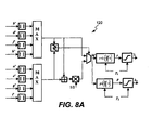
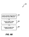
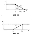
- Fig. 8A shows a block diagram of smooth attenuation module 120 for a 3x3 sliding window that performs a smooth attenuation operation 800.
- Fig. 8B shows a flow diagram of a method 800 for performing the smooth attenuation operation.
- the dynamic range measure M is calculated from the pixel value differences, as explained above.
- corner pixel differences a' , c' , g' , i' have twice less influence and contribution than "cross" pixel differences b',d', f',h' to the output value.
- the output value of the MPEG artifact attenuation factor ⁇ is applied to limit application of the nonlinear function to the selected pixel value e.
- the smooth attenuation module 120 also computes and outputs a Gaussian Noise attenuation factor ⁇ 1 that is one of the inputs to the output module 125.
- Gaussian Noise attenuation is disabled, by switch 145 in Fig. 1 , the value of ⁇ 1 has to be equal to unity, and the residual value inside the output module 125 is not modified as will be described below.
- the value of ⁇ 1 equals 0, the residual value inside the output module 125 is forced to the local DC value.
- the zone where ⁇ 1 equals 0 is defined by the dynamic range measure M and the threshold T 2 when M ⁇ T 2 .
- Fig. 9B shows a graphical illustration of the smoothing coefficient ⁇ 1 as a function of M for various values of T 2 .
- the output module 125 provides application of the nonlinear function ⁇ ( ⁇ ), multiplied by the parameter ⁇ in module 130 and entered to a first input of the MPEG artifact reduction on/off switch 140 in Fig. 1 .
- the second input of the switch 140 is a Local DC value with the reversed - E DC .
- MPEG artifact reduction mode When switch 140 is in the 'on' position, MPEG artifact reduction mode is enabled. When switch 140 is in the 'off' position, MPEG artifact reduction mode is disabled.
- the input value 134 to the output module 125 is ⁇ ( ⁇ ), and when the MPEG artifact reduction mode is disabled, the input value is - E DC .
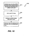
- Fig. 10 shows a flow diagram of a method 1000 performed by the output module 125 Fig. 1 .
- the input value 134 from switch 140 is multiplied by input value 133, that is, the Gaussian Noise attenuation factor ⁇ 1 .
- the result is added to input signal 132, that is, the local DC value, to compute value 135.
- step 1030 the value 135 is multiplied by the MPEG artifact attenuation factor ⁇ , that is, value 104, to control the applicability of the artifact reduction with respect to the dynamic range measure M.
- Embodiments of the invention can be implemented in digital electronic circuitry, or in computer hardware, firmware, software, or in combinations of them.
- Apparatus embodiments of the invention can be implemented in a computer program product tangibly embodied in a machine-readable storage device for execution by a programmable processor; and method steps of the invention can be performed by a programmable processor executing a program of instructions to perform functions of the invention by operating on input data and generating output.
- Embodiments of the invention can be implemented advantageously in one or more computer programs that are executable on a programmable system including at least one programmable processor coupled to receive data and instructions from, and to transmit data and instructions to, a data storage system, at least one input device, and at least one output device.
- Each computer program can be implemented in a high-level procedural or object-oriented programming language, or in assembly or machine language if desired; and in any case, the language can be a compiled or interpreted language.
- Suitable processors include, by way of example, both general and special purpose microprocessors. Generally, a processor will receive instructions and data from a read-only memory and/or a random access memory. Generally, a computer will include one or more mass storage devices for storing data files; such devices include magnetic disks, such as internal hard disks and removable disks; magneto-optical disks; and optical disks. Storage devices suitable for tangibly embodying computer program instructions and data include all forms of non-volatile memory, including by way of example semiconductor memory devices, such as EPROM, EEPROM, and flash memory devices; magnetic disks such as internal hard disks and removable disks; magneto-optical disks; and CD-ROM disks. Any of the foregoing can be supplemented by, or incorporated in, ASICs (application-specific integrated circuits).
- ASICs application-specific integrated circuits
Landscapes
- Engineering & Computer Science (AREA)
- Multimedia (AREA)
- Signal Processing (AREA)
- Compression Or Coding Systems Of Tv Signals (AREA)
- Image Processing (AREA)
- Picture Signal Circuits (AREA)
- Ultra Sonic Daignosis Equipment (AREA)
- Apparatus For Radiation Diagnosis (AREA)
Claims (9)
- Procédé de réduction d'effet Gibb dans une trame d'image d'un signal vidéo, le procédé comprenant les étapes consistant à :examiner (210) une fenêtre (300) de la trame d'image, la fenêtre (300) comprenant une pluralité de valeurs de pixel ;soustraire (215) une valeur e choisie des valeurs de pixel parmi les valeurs de pixel dans la fenêtre (300) afin de définir une fenêtre modifiée (350) de différences de valeur de pixel ;caractérisé en ce que le procédé comprend en outre les étapes consistant à :limiter une plage dynamique des différences de valeur de pixel (505) dans la fenêtre modifiée (350) de différences de valeur de pixel à une plage -T1 à +T1 à l'aide d'un seuil T1 obtenant ainsi une fenêtre modifiée de différences de valeur de pixel limitées ;calculer (220, 511) une valeur moyenne locale EDC des différences de valeur de pixel limitées dans la fenêtre modifiée de différences de valeur de pixel limitées ;appliquer (510) un filtre passe-haut 2D (415) aux différences de valeur de pixel limitées dans la fenêtre modifiée de différences de valeur de pixel limitées afin de générer une valeur de réduction Ecb ;calculer (515) un coefficient de pondération α en fonction d'une variance des différences de valeur de pixel limitées dans la fenêtre modifiée de différences de valeur de pixel limitées ;calculer (520) une somme pondérée de la valeur de réduction Ecb et de la valeur moyenne locale EDC après multiplication avec le facteur de pondération α afin de définir une valeur de réduction d'effet Gibb u selon la relation :
 générer (600) une fonction non linéaire ψ(Δ) d'une différence Δ entre la valeur de réduction d'effet Gibb u et la valeur moyenne locale EDC ;calculer (820) un facteur d'atténuation d'artéfact λ en fonction d'une mesure de plage dynamique des différences de valeur de pixel dans la fenêtre modifiée (350) de différences de valeur de pixel et du seuil T1 ;additionner (1020) la valeur moyenne locale EDC à ψ (Δ) ;multiplier (1030) le facteur d'atténuation d'artéfact λ par la somme de la valeur moyenne locale EDC et de ψ (Δ) ; etadditionner (1040) la valeur e choisie des valeurs de pixel du produit du facteur d'atténuation d'artéfact λ et la somme de la valeur moyenne locale EDC et de ψ(Δ) afin de générer une valeur de pixel modifiée.
 - Procédé selon la revendication 1, dans lequel le calcul (220) de la valeur moyenne locale EDC comprend l'application d'un filtre passe-bas 2D (410) aux différences de valeur de pixel limitées dans la fenêtre modifiée (350) de différences de valeur de pixel limitées.
- Procédé selon la revendication 1, dans lequel la valeur de pixel choisie est un pixel central de la fenêtre (300).
- Procédé selon la revendication 1, dans lequel la fenêtre (300) est une fenêtre nXn de pixels.
- Procédé selon la revendication 4, dans lequel n est un petit nombre impair.
- Procédé selon la revendication 5, dans lequel n = 3.
- Appareil (100) permettant de réduire l'effet Gibb dans une trame d'image d'un signal vidéo, l'appareil comprenant :un module de fenêtrage (105) configuré pour examiner une fenêtre (300) de la trame d'image, la fenêtre (300) comprenant une pluralité de valeurs de pixel ;un module de soustraction (305) configuré pour soustraire une valeur e choisie des valeurs de pixel parmi les valeurs de pixel dans la fenêtre (300) afin de définir une fenêtre modifiée (350) de différences de valeur de pixel ;un moyen permettant de limiter une plage dynamique des différences de valeur de pixel (405, 505) dans la fenêtre modifiée (350) de différences de valeur de pixel à une plage -T1 à +T1 à l'aide d'un seuil T1 obtenant ainsi une fenêtre modifiée de différences de valeur de pixel limitées ;un module de détermination de moyenne locale (110, 410) configuré pour calculer une valeur moyenne locale EDC des différences de valeur de pixel limitées dans la fenêtre modifiée de différences de valeur de pixel limitées ;un module de réduction d'effet Gibb (110) configuré pour générer une valeur de réduction d'effet Gibb u pour les différences de valeur de pixel limitées dans la fenêtre modifiée de différences de valeur de pixel limitées, dans lequel le module de réduction d'effet Gibb comprend :un filtre passe-haut 2D (415) configuré pour générer une valeur de réduction Ecb lorsqu'il est appliqué aux différences de valeur de pixel limitées dans la fenêtre modifiée de différences de valeur de pixel limitées ;un module de variance (420) configuré pour calculer un coefficient de pondération α en fonction d'une variance des différences de valeur de pixel limitées dans la fenêtre modifiée de différences de valeur de pixel limitées ; etun module de sommation (425) configuré pour calculer une somme pondérée de la valeur de réduction Ecb et de la valeur moyenne locale EDC afin de définir une valeur de réduction d'effet Gibb u selon la relation :
 un module de traitement non linéaire (115) configuré pour générer une fonction non linéaire ψ(Δ) d'une différence Δ entre la valeur de réduction d'effet Gibb u et la valeur moyenne locale EDC ;un module d'atténuation lisse (120) configuré pour calculer un facteur d'atténuation d'artéfact λ en fonction d'une mesure de plage dynamique des différences de valeur de pixel dans la fenêtre modifiée (350) de différences de valeur de pixel et du seuil T1 ; etun module de sortie (125) configuré pour :- additionner la valeur moyenne locale EDC à ψ(Δ) ;- multiplier le facteur d'atténuation d'artéfact λ par la somme de la valeur moyenne locale EDC et de ψ(Δ) ; etadditionner la valeur e choisie des valeurs de pixel du produit du facteur d'atténuation d'artéfact λ et la somme de la valeur moyenne locale EDC et de ψ(Δ) afin de générer une valeur de pixel modifiée.
 - Programme informatique comprenant un moyen de code pour une exécution par un système informatique, dans lequel le moyen de code comprend des instructions qui mettent en oeuvre le procédé de l'une quelconque des revendications 1 à 6, lorsqu'il est exécuté par le système informatique.
- Produit de programme informatique comprenant un support lisible par ordinateur sur lequel est intégré un programme informatique selon la revendication 8.
Applications Claiming Priority (4)
| Application Number | Priority Date | Filing Date | Title |
|---|---|---|---|
| US53030703P | 2003-12-16 | 2003-12-16 | |
| US530307P | 2003-12-16 | ||
| US964197 | 2004-10-12 | ||
| US10/964,197 US7346226B2 (en) | 2003-12-16 | 2004-10-12 | Method and apparatus for MPEG artifacts reduction |
Publications (3)
| Publication Number | Publication Date |
|---|---|
| EP1545134A2 EP1545134A2 (fr) | 2005-06-22 |
| EP1545134A3 EP1545134A3 (fr) | 2006-05-24 |
| EP1545134B1 true EP1545134B1 (fr) | 2012-05-02 |
Family
ID=34527142
Family Applications (1)
| Application Number | Title | Priority Date | Filing Date |
|---|---|---|---|
| EP04257653A Active EP1545134B1 (fr) | 2003-12-16 | 2004-12-09 | Méthode et appareil pour réduire les artefacts MPEG |
Country Status (8)
| Country | Link |
|---|---|
| US (1) | US7346226B2 (fr) |
| EP (1) | EP1545134B1 (fr) |
| JP (1) | JP4880895B2 (fr) |
| KR (1) | KR101084513B1 (fr) |
| CN (1) | CN100566416C (fr) |
| AT (1) | ATE556538T1 (fr) |
| SG (1) | SG112928A1 (fr) |
| TW (1) | TWI361398B (fr) |
Cited By (1)
| Publication number | Priority date | Publication date | Assignee | Title |
|---|---|---|---|---|
| EP3459245B1 (fr) * | 2016-05-16 | 2022-07-27 | QUALCOMM Incorporated | Confusion de filtres multiples dans le filtrage en boucle adaptative en codage vidéo |
Families Citing this family (37)
| Publication number | Priority date | Publication date | Assignee | Title |
|---|---|---|---|---|
| US7602991B2 (en) * | 2001-10-24 | 2009-10-13 | Nik Software, Inc. | User definable image reference regions |
| CN100389428C (zh) | 2001-10-24 | 2008-05-21 | Nik软件公司 | 用于利用图像基准点处理数字图像的方法和设备 |
| US7346226B2 (en) * | 2003-12-16 | 2008-03-18 | Genesis Microchip Inc. | Method and apparatus for MPEG artifacts reduction |
| US7457438B2 (en) * | 2003-12-23 | 2008-11-25 | Genesis Microchip Inc. | Robust camera pan vector estimation using iterative center of mass |
| US7480334B2 (en) * | 2003-12-23 | 2009-01-20 | Genesis Microchip Inc. | Temporal motion vector filtering |
| US7499494B2 (en) * | 2003-12-23 | 2009-03-03 | Genesis Microchip Inc. | Vector selection decision for pixel interpolation |
| CA2563107C (fr) * | 2004-03-29 | 2014-03-04 | Nielsen Media Research, Inc. | Procedes et appareils permettant de detecter une trame vide dans un signal de diffusion video numerique |
| US7869500B2 (en) * | 2004-04-27 | 2011-01-11 | Broadcom Corporation | Video encoder and method for detecting and encoding noise |
| US7949051B2 (en) * | 2004-05-26 | 2011-05-24 | Broadcom Corporation | Mosquito noise detection and reduction |
| US8194757B2 (en) * | 2005-01-28 | 2012-06-05 | Broadcom Corporation | Method and system for combining results of mosquito noise reduction and block noise reduction |
| US8254462B2 (en) * | 2005-01-28 | 2012-08-28 | Broadcom Corporation | Method and system for block noise reduction |
| US8218655B2 (en) | 2005-09-19 | 2012-07-10 | Maxim Integrated Products, Inc. | Method, system and device for improving video quality through in-loop temporal pre-filtering |
| US8265145B1 (en) * | 2006-01-13 | 2012-09-11 | Vbrick Systems, Inc. | Management and selection of reference frames for long term prediction in motion estimation |
| WO2007083252A1 (fr) * | 2006-01-18 | 2007-07-26 | Koninklijke Philips Electronics N.V. | Réduction de bruit spatial |
| KR100843084B1 (ko) * | 2006-06-22 | 2008-07-02 | 삼성전자주식회사 | 노이즈 저감 방법 및 장치 |
| US7778482B2 (en) * | 2006-07-19 | 2010-08-17 | Trident Microsystems (Far East) Ltd. | Method and system for reducing mosquito noise in a digital image |
| US7796834B2 (en) * | 2006-11-16 | 2010-09-14 | Texas Instruments Incorporated | Post-processing technique for noise reduction of DCT-based compressed images |
| US20080143873A1 (en) * | 2006-12-15 | 2008-06-19 | Darren Neuman | Tv user interface and processing for personal video players |
| US7903900B2 (en) * | 2007-03-30 | 2011-03-08 | Hong Kong Applied Science And Technology Research Institute Co., Ltd. | Low complexity color de-noising filter |
| US7889942B2 (en) * | 2007-05-25 | 2011-02-15 | Zoran Corporation | Dynamic range compensation-dependent noise reduction |
| US7995856B2 (en) * | 2007-05-25 | 2011-08-09 | Zoran Corporation | Dynamic range compensation-dependent noise reduction |
| US8306272B2 (en) * | 2007-05-31 | 2012-11-06 | Microsemi Corporation | Method and system for dynamically altering the analysis methodology of millimeter wave imagery in response to the range and direction of motion of a subject |
| US9131213B2 (en) | 2007-09-07 | 2015-09-08 | Evertz Microsystems Ltd. | Method of generating a blockiness indicator for a video signal |
| KR101303660B1 (ko) * | 2007-10-01 | 2013-09-04 | 삼성전자주식회사 | 잡음제거를 고려한 선명도 향상 방법 및 장치 그리고 잡음가중치 계산 방법 및 장치 |
| TW200917824A (en) * | 2007-10-12 | 2009-04-16 | Univ Nat Taiwan | Shockproof method for digital imaging |
| KR100927458B1 (ko) * | 2007-12-27 | 2009-11-19 | 건국대학교 산학협력단 | 정렬과 평균 연산 조합에 의한 공간영역에서의 필터 처리방법 |
| CN101527840B (zh) * | 2008-03-06 | 2011-06-01 | 瑞昱半导体股份有限公司 | 滤除蚊子噪声的影像处理方法及装置 |
| EP2311007B1 (fr) * | 2008-08-08 | 2016-12-28 | Thomson Licensing | Procédé et appareil de détection d'artéfacts en bande |
| GB2465158A (en) * | 2008-11-05 | 2010-05-12 | Sony Corp | Image data filtering |
| KR101631270B1 (ko) | 2009-06-19 | 2016-06-16 | 삼성전자주식회사 | 의사 난수 필터를 이용한 영상 필터링 방법 및 장치 |
| US8306355B2 (en) * | 2009-07-13 | 2012-11-06 | Sharp Laboratories Of America, Inc. | Methods and systems for reducing compression artifacts |
| US9363534B2 (en) * | 2009-10-29 | 2016-06-07 | Vestel Elektronik Sanayi Ve Ticaret A.S. | Method and device for processing a video sequence |
| US8925024B2 (en) | 2009-12-31 | 2014-12-30 | The Nielsen Company (Us), Llc | Methods and apparatus to detect commercial advertisements associated with media presentations |
| US8588551B2 (en) * | 2010-03-01 | 2013-11-19 | Microsoft Corp. | Multi-image sharpening and denoising using lucky imaging |
| WO2013011671A1 (fr) * | 2011-07-15 | 2013-01-24 | パナソニック株式会社 | Dispositif de transmission et procédé de transmission |
| US9924200B2 (en) | 2013-01-24 | 2018-03-20 | Microsoft Technology Licensing, Llc | Adaptive noise reduction engine for streaming video |
| US9848222B2 (en) | 2015-07-15 | 2017-12-19 | The Nielsen Company (Us), Llc | Methods and apparatus to detect spillover |
Family Cites Families (46)
| Publication number | Priority date | Publication date | Assignee | Title |
|---|---|---|---|---|
| US4651211A (en) | 1986-01-17 | 1987-03-17 | Rca Corporation | Video signal motion detecting apparatus |
| JPH01500236A (ja) | 1986-03-19 | 1989-01-26 | ブリティッシュ・ブロードキャスティング・コーポレーション | 帯域巾圧縮ビデオ信号の受信再生装置 |
| EP0294956B1 (fr) | 1987-06-09 | 1994-07-20 | Sony Corporation | Réduction de vecteurs de mouvement dans des images de télévision |
| FR2633468B1 (fr) | 1988-06-24 | 1990-11-09 | France Etat | Procede de codage de donnees d'assistance a la reconstruction d'images electroniques animees sous-echantillonnees |
| DE68925880T2 (de) | 1988-12-28 | 1996-08-01 | Nippon Denki Home Electronics | Bewegungsdetektion und Y/C Trennschaltung und -verfahren zur Detektion einer Bewegung in einem Fernsehwiedergabebild |
| DE69029999T2 (de) | 1990-07-20 | 1997-08-14 | Philips Electronics Nv | Vorrichtung zur Verarbeitung von Bewegungsvektoren |
| JP3344957B2 (ja) * | 1990-09-07 | 2002-11-18 | 株式会社リコー | 画像処理方法 |
| US5317397A (en) | 1991-05-31 | 1994-05-31 | Kabushiki Kaisha Toshiba | Predictive coding using spatial-temporal filtering and plural motion vectors |
| US5799111A (en) * | 1991-06-14 | 1998-08-25 | D.V.P. Technologies, Ltd. | Apparatus and methods for smoothing images |
| US5259040A (en) | 1991-10-04 | 1993-11-02 | David Sarnoff Research Center, Inc. | Method for determining sensor motion and scene structure and image processing system therefor |
| US5596659A (en) | 1992-09-01 | 1997-01-21 | Apple Computer, Inc. | Preprocessing and postprocessing for vector quantization |
| US5539663A (en) * | 1993-11-24 | 1996-07-23 | Intel Corporation | Process, apparatus and system for encoding and decoding video signals using temporal filtering |
| GB2286740B (en) | 1994-02-21 | 1998-04-01 | Sony Uk Ltd | Coding and decoding of video signals |
| CN1127906A (zh) | 1995-01-26 | 1996-07-31 | 大宇电子株式会社 | 运动矢量检测设备 |
| JP3480477B2 (ja) | 1995-07-26 | 2003-12-22 | ソニー株式会社 | 動き検出回路および動き検出方法、並びに輝度・色信号分離装置 |
| US5819035A (en) * | 1995-10-20 | 1998-10-06 | Matsushita Electric Industrial Co., Ltd. | Post-filter for removing ringing artifacts of DCT coding |
| US6041145A (en) * | 1995-11-02 | 2000-03-21 | Matsushita Electric Industrial Co., Ltd. | Device and method for smoothing picture signal, device and method for encoding picture and device and method for decoding picture |
| EP0772365A3 (fr) | 1995-11-02 | 1999-05-12 | Matsushita Electric Industrial Co., Ltd. | Méthode et dispositif pour le filtrage d'un signal d'image, et codage/décodage l'utilisant |
| GB2311183A (en) | 1996-03-13 | 1997-09-17 | Innovision Plc | Gradient based motion estimation |
| JP4159606B2 (ja) | 1996-05-24 | 2008-10-01 | コーニンクレッカ フィリップス エレクトロニクス エヌ ヴィ | 動き推定 |
| US5943445A (en) | 1996-12-19 | 1999-08-24 | Digital Equipment Corporation | Dynamic sprites for encoding video data |
| US6236763B1 (en) | 1997-09-19 | 2001-05-22 | Texas Instruments Incorporated | Method and apparatus for removing noise artifacts in decompressed video signals |
| US6178205B1 (en) | 1997-12-12 | 2001-01-23 | Vtel Corporation | Video postfiltering with motion-compensated temporal filtering and/or spatial-adaptive filtering |
| US6128047A (en) | 1998-05-20 | 2000-10-03 | Sony Corporation | Motion estimation process and system using sparse search block-matching and integral projection |
| WO2000030359A1 (fr) | 1998-11-17 | 2000-05-25 | Koninklijke Philips Electronics N.V. | Procede de transcodage de signaux video codes et transcodeur correspondant avec selection des vecteurs de mouvement |
| EP1062815A1 (fr) | 1999-01-12 | 2000-12-27 | Koninklijke Philips Electronics N.V. | Evaluation des parametres de mouvement d'une camera |
| US6658059B1 (en) | 1999-01-15 | 2003-12-02 | Digital Video Express, L.P. | Motion field modeling and estimation using motion transform |
| US6809758B1 (en) | 1999-12-29 | 2004-10-26 | Eastman Kodak Company | Automated stabilization method for digital image sequences |
| US6359658B1 (en) * | 2000-03-06 | 2002-03-19 | Philips Electronics North America Corporation | Subjective noise measurement on active video signal |
| DE10037491A1 (de) | 2000-08-01 | 2002-02-14 | Stryker Leibinger Gmbh & Co Kg | Verfahren zum dreidimensionalen Visualisieren von Strukturen im Körperinneren |
| AU2001285270A1 (en) | 2000-08-28 | 2002-03-13 | Thomson Licensing S.A. | Method and apparatus for motion compensated temporal interpolation of video sequences |
| US6738099B2 (en) | 2001-02-16 | 2004-05-18 | Tektronix, Inc. | Robust camera motion estimation for video sequences |
| US6782054B2 (en) | 2001-04-20 | 2004-08-24 | Koninklijke Philips Electronics, N.V. | Method and apparatus for motion vector estimation |
| US6909750B2 (en) | 2001-05-01 | 2005-06-21 | Koninklijke Philips Electronics N.V. | Detection and proper interpolation of interlaced moving areas for MPEG decoding with embedded resizing |
| KR100393066B1 (ko) | 2001-06-11 | 2003-07-31 | 삼성전자주식회사 | 적응 움직임 보상형 디-인터레이싱 장치 및 그 방법 |
| WO2002102086A2 (fr) * | 2001-06-12 | 2002-12-19 | Miranda Technologies Inc. | Appareil et procede pour la reduction spatiale, adaptative a base de segmentation, de nuisances pour des signaux d'image codes |
| US7003173B2 (en) * | 2001-06-12 | 2006-02-21 | Sharp Laboratories Of America, Inc. | Filter for combined de-ringing and edge sharpening |
| EP1440581B1 (fr) | 2001-07-10 | 2014-10-08 | Entropic Communications, Inc. | Unite et procede d'estimation de mouvement et appareil de traitement de l'image dote d'une telle unite d'estimation de mouvement |
| JP4769388B2 (ja) | 2001-08-07 | 2011-09-07 | キヤノン株式会社 | 画像データ処理装置及び画像データ処理方法 |
| US7227896B2 (en) | 2001-10-04 | 2007-06-05 | Sharp Laboratories Of America, Inc. | Method and apparatus for global motion estimation |
| KR100396558B1 (ko) | 2001-10-25 | 2003-09-02 | 삼성전자주식회사 | 적응 움직임 보상형 프레임 및/또는 레이트 변환 장치 및그 방법 |
| CN101448162B (zh) | 2001-12-17 | 2013-01-02 | 微软公司 | 处理视频图像的方法 |
| US7609763B2 (en) | 2003-07-18 | 2009-10-27 | Microsoft Corporation | Advanced bi-directional predictive coding of video frames |
| KR100564592B1 (ko) * | 2003-12-11 | 2006-03-28 | 삼성전자주식회사 | 동영상 데이터 잡음제거방법 |
| US7346226B2 (en) * | 2003-12-16 | 2008-03-18 | Genesis Microchip Inc. | Method and apparatus for MPEG artifacts reduction |
| JP2005304005A (ja) | 2004-04-13 | 2005-10-27 | Samsung Electronics Co Ltd | ビデオフレームに対する動き推定方法及びビデオエンコーダ |
-
2004
- 2004-10-12 US US10/964,197 patent/US7346226B2/en active Active
- 2004-11-22 SG SG200406810A patent/SG112928A1/en unknown
- 2004-11-29 TW TW093136775A patent/TWI361398B/zh active
- 2004-12-02 KR KR1020040100131A patent/KR101084513B1/ko active IP Right Grant
- 2004-12-09 AT AT04257653T patent/ATE556538T1/de active
- 2004-12-09 EP EP04257653A patent/EP1545134B1/fr active Active
- 2004-12-14 JP JP2004361159A patent/JP4880895B2/ja active Active
- 2004-12-15 CN CNB2004101021675A patent/CN100566416C/zh active Active
Cited By (1)
| Publication number | Priority date | Publication date | Assignee | Title |
|---|---|---|---|---|
| EP3459245B1 (fr) * | 2016-05-16 | 2022-07-27 | QUALCOMM Incorporated | Confusion de filtres multiples dans le filtrage en boucle adaptative en codage vidéo |
Also Published As
| Publication number | Publication date |
|---|---|
| JP2005184819A (ja) | 2005-07-07 |
| US20050129330A1 (en) | 2005-06-16 |
| KR101084513B1 (ko) | 2011-11-18 |
| US7346226B2 (en) | 2008-03-18 |
| CN1652606A (zh) | 2005-08-10 |
| TWI361398B (en) | 2012-04-01 |
| JP4880895B2 (ja) | 2012-02-22 |
| SG112928A1 (en) | 2005-07-28 |
| EP1545134A2 (fr) | 2005-06-22 |
| CN100566416C (zh) | 2009-12-02 |
| ATE556538T1 (de) | 2012-05-15 |
| TW200523820A (en) | 2005-07-16 |
| EP1545134A3 (fr) | 2006-05-24 |
| KR20050061303A (ko) | 2005-06-22 |
Similar Documents
| Publication | Publication Date | Title |
|---|---|---|
| EP1545134B1 (fr) | Méthode et appareil pour réduire les artefacts MPEG | |
| JP2673778B2 (ja) | 動画像の復号化における雑音低減装置 | |
| EP2532161B1 (fr) | Commande de filtrage à dégroupage | |
| US7460596B2 (en) | Adaptive de-blocking filtering apparatus and method for MPEG video decoder | |
| US7539248B2 (en) | Adaptive de-blocking filtering apparatus and method for MPEG video decoder | |
| US7397853B2 (en) | Adaptive de-blocking filtering apparatus and method for MPEG video decoder | |
| EP2327219B1 (fr) | Reduire le bruit d'une image numerique | |
| US7860167B2 (en) | Apparatus and method for adaptive 3D artifact reducing for encoded image signal | |
| US7397854B2 (en) | Adaptive de-blocking filtering apparatus and method for MPEG video decoder | |
| US6845180B2 (en) | Predicting ringing artifacts in digital images | |
| US7496141B2 (en) | Adaptive de-blocking filtering apparatus and method for MPEG video decoder | |
| EP0771116A2 (fr) | Appareil de traitement d'image | |
| EP2403257A2 (fr) | Encodage et décodage d'image de profondeur | |
| EP1784023A2 (fr) | Réduction des artefacts de bloc complétée par un procédé optionnel de dithering | |
| US20090080517A1 (en) | Method and Related Device for Reducing Blocking Artifacts in Video Streams | |
| US20130022288A1 (en) | Image processing apparatus and method for reducing edge-induced artefacts | |
| US20050243914A1 (en) | Adaptive de-blocking filtering apparatus and method for mpeg video decoder | |
| Vidal et al. | New adaptive filters as perceptual preprocessing for rate-quality performance optimization of video coding | |
| Song et al. | Efficient debanding filtering for inverse tone mapped high dynamic range videos | |
| WO2002096117A1 (fr) | Degroupage de donnees video en blocs | |
| US7616829B1 (en) | Reducing undesirable block based image processing artifacts by DC image filtering | |
| Zhang et al. | Compression artifact reduction with adaptive bilateral filtering | |
| EP1874058A2 (fr) | Réduction adaptative d'artéfacts MPEG locaux | |
| Kim | Adaptive blocking artifact reduction using wavelet-based block analysis | |
| JP2001346208A (ja) | 画像信号復号化装置および方法 |
Legal Events
| Date | Code | Title | Description |
|---|---|---|---|
| PUAI | Public reference made under article 153(3) epc to a published international application that has entered the european phase |
Free format text: ORIGINAL CODE: 0009012 |
|
| AK | Designated contracting states |
Kind code of ref document: A2 Designated state(s): AT BE BG CH CY CZ DE DK EE ES FI FR GB GR HU IE IS IT LI LT LU MC NL PL PT RO SE SI SK TR |
|
| AX | Request for extension of the european patent |
Extension state: AL BA HR LV MK YU |
|
| RIN1 | Information on inventor provided before grant (corrected) |
Inventor name: SHYSHKIN, VYACHESLAV |
|
| 17P | Request for examination filed |
Effective date: 20051220 |
|
| PUAL | Search report despatched |
Free format text: ORIGINAL CODE: 0009013 |
|
| AK | Designated contracting states |
Kind code of ref document: A3 Designated state(s): AT BE BG CH CY CZ DE DK EE ES FI FR GB GR HU IE IS IT LI LT LU MC NL PL PT RO SE SI SK TR |
|
| AX | Request for extension of the european patent |
Extension state: AL BA HR LV MK YU |
|
| 17Q | First examination report despatched |
Effective date: 20060911 |
|
| AKX | Designation fees paid |
Designated state(s): AT BE BG CH CY CZ DE DK EE ES FI FR GB GR HU IE IS IT LI LT LU MC NL PL PT RO SE SI SK TR |
|
| RAP1 | Party data changed (applicant data changed or rights of an application transferred) |
Owner name: GENESIS MICROCHIP, INC. |
|
| RAP1 | Party data changed (applicant data changed or rights of an application transferred) |
Owner name: TAMIRAS PER PTE. LTD., LLC |
|
| GRAC | Information related to communication of intention to grant a patent modified |
Free format text: ORIGINAL CODE: EPIDOSCIGR1 |
|
| GRAP | Despatch of communication of intention to grant a patent |
Free format text: ORIGINAL CODE: EPIDOSNIGR1 |
|
| GRAS | Grant fee paid |
Free format text: ORIGINAL CODE: EPIDOSNIGR3 |
|
| GRAA | (expected) grant |
Free format text: ORIGINAL CODE: 0009210 |
|
| AK | Designated contracting states |
Kind code of ref document: B1 Designated state(s): AT BE BG CH CY CZ DE DK EE ES FI FR GB GR HU IE IS IT LI LT LU MC NL PL PT RO SE SI SK TR |
|
| REG | Reference to a national code |
Ref country code: GB Ref legal event code: FG4D |
|
| REG | Reference to a national code |
Ref country code: CH Ref legal event code: EP Ref country code: AT Ref legal event code: REF Ref document number: 556538 Country of ref document: AT Kind code of ref document: T Effective date: 20120515 |
|
| REG | Reference to a national code |
Ref country code: IE Ref legal event code: FG4D |
|
| REG | Reference to a national code |
Ref country code: DE Ref legal event code: R096 Ref document number: 602004037586 Country of ref document: DE Effective date: 20120705 |
|
| REG | Reference to a national code |
Ref country code: NL Ref legal event code: VDEP Effective date: 20120502 |
|
| REG | Reference to a national code |
Ref country code: LT Ref legal event code: MG4D Effective date: 20120502 |
|
| PG25 | Lapsed in a contracting state [announced via postgrant information from national office to epo] |
Ref country code: IS Free format text: LAPSE BECAUSE OF FAILURE TO SUBMIT A TRANSLATION OF THE DESCRIPTION OR TO PAY THE FEE WITHIN THE PRESCRIBED TIME-LIMIT Effective date: 20120902 Ref country code: LT Free format text: LAPSE BECAUSE OF FAILURE TO SUBMIT A TRANSLATION OF THE DESCRIPTION OR TO PAY THE FEE WITHIN THE PRESCRIBED TIME-LIMIT Effective date: 20120502 Ref country code: PL Free format text: LAPSE BECAUSE OF FAILURE TO SUBMIT A TRANSLATION OF THE DESCRIPTION OR TO PAY THE FEE WITHIN THE PRESCRIBED TIME-LIMIT Effective date: 20120502 Ref country code: SE Free format text: LAPSE BECAUSE OF FAILURE TO SUBMIT A TRANSLATION OF THE DESCRIPTION OR TO PAY THE FEE WITHIN THE PRESCRIBED TIME-LIMIT Effective date: 20120502 Ref country code: FI Free format text: LAPSE BECAUSE OF FAILURE TO SUBMIT A TRANSLATION OF THE DESCRIPTION OR TO PAY THE FEE WITHIN THE PRESCRIBED TIME-LIMIT Effective date: 20120502 Ref country code: CY Free format text: LAPSE BECAUSE OF FAILURE TO SUBMIT A TRANSLATION OF THE DESCRIPTION OR TO PAY THE FEE WITHIN THE PRESCRIBED TIME-LIMIT Effective date: 20120502 |
|
| REG | Reference to a national code |
Ref country code: AT Ref legal event code: MK05 Ref document number: 556538 Country of ref document: AT Kind code of ref document: T Effective date: 20120502 |
|
| PG25 | Lapsed in a contracting state [announced via postgrant information from national office to epo] |
Ref country code: SI Free format text: LAPSE BECAUSE OF FAILURE TO SUBMIT A TRANSLATION OF THE DESCRIPTION OR TO PAY THE FEE WITHIN THE PRESCRIBED TIME-LIMIT Effective date: 20120502 Ref country code: GR Free format text: LAPSE BECAUSE OF FAILURE TO SUBMIT A TRANSLATION OF THE DESCRIPTION OR TO PAY THE FEE WITHIN THE PRESCRIBED TIME-LIMIT Effective date: 20120803 Ref country code: PT Free format text: LAPSE BECAUSE OF FAILURE TO SUBMIT A TRANSLATION OF THE DESCRIPTION OR TO PAY THE FEE WITHIN THE PRESCRIBED TIME-LIMIT Effective date: 20120903 |
|
| PG25 | Lapsed in a contracting state [announced via postgrant information from national office to epo] |
Ref country code: BE Free format text: LAPSE BECAUSE OF FAILURE TO SUBMIT A TRANSLATION OF THE DESCRIPTION OR TO PAY THE FEE WITHIN THE PRESCRIBED TIME-LIMIT Effective date: 20120502 |
|
| PG25 | Lapsed in a contracting state [announced via postgrant information from national office to epo] |
Ref country code: AT Free format text: LAPSE BECAUSE OF FAILURE TO SUBMIT A TRANSLATION OF THE DESCRIPTION OR TO PAY THE FEE WITHIN THE PRESCRIBED TIME-LIMIT Effective date: 20120502 Ref country code: RO Free format text: LAPSE BECAUSE OF FAILURE TO SUBMIT A TRANSLATION OF THE DESCRIPTION OR TO PAY THE FEE WITHIN THE PRESCRIBED TIME-LIMIT Effective date: 20120502 Ref country code: NL Free format text: LAPSE BECAUSE OF FAILURE TO SUBMIT A TRANSLATION OF THE DESCRIPTION OR TO PAY THE FEE WITHIN THE PRESCRIBED TIME-LIMIT Effective date: 20120502 Ref country code: DK Free format text: LAPSE BECAUSE OF FAILURE TO SUBMIT A TRANSLATION OF THE DESCRIPTION OR TO PAY THE FEE WITHIN THE PRESCRIBED TIME-LIMIT Effective date: 20120502 Ref country code: EE Free format text: LAPSE BECAUSE OF FAILURE TO SUBMIT A TRANSLATION OF THE DESCRIPTION OR TO PAY THE FEE WITHIN THE PRESCRIBED TIME-LIMIT Effective date: 20120502 Ref country code: CZ Free format text: LAPSE BECAUSE OF FAILURE TO SUBMIT A TRANSLATION OF THE DESCRIPTION OR TO PAY THE FEE WITHIN THE PRESCRIBED TIME-LIMIT Effective date: 20120502 Ref country code: SK Free format text: LAPSE BECAUSE OF FAILURE TO SUBMIT A TRANSLATION OF THE DESCRIPTION OR TO PAY THE FEE WITHIN THE PRESCRIBED TIME-LIMIT Effective date: 20120502 |
|
| PG25 | Lapsed in a contracting state [announced via postgrant information from national office to epo] |
Ref country code: IT Free format text: LAPSE BECAUSE OF FAILURE TO SUBMIT A TRANSLATION OF THE DESCRIPTION OR TO PAY THE FEE WITHIN THE PRESCRIBED TIME-LIMIT Effective date: 20120502 |
|
| PLBE | No opposition filed within time limit |
Free format text: ORIGINAL CODE: 0009261 |
|
| STAA | Information on the status of an ep patent application or granted ep patent |
Free format text: STATUS: NO OPPOSITION FILED WITHIN TIME LIMIT |
|
| 26N | No opposition filed |
Effective date: 20130205 |
|
| PG25 | Lapsed in a contracting state [announced via postgrant information from national office to epo] |
Ref country code: ES Free format text: LAPSE BECAUSE OF FAILURE TO SUBMIT A TRANSLATION OF THE DESCRIPTION OR TO PAY THE FEE WITHIN THE PRESCRIBED TIME-LIMIT Effective date: 20120813 |
|
| REG | Reference to a national code |
Ref country code: DE Ref legal event code: R097 Ref document number: 602004037586 Country of ref document: DE Effective date: 20130205 |
|
| PG25 | Lapsed in a contracting state [announced via postgrant information from national office to epo] |
Ref country code: MC Free format text: LAPSE BECAUSE OF NON-PAYMENT OF DUE FEES Effective date: 20121231 Ref country code: BG Free format text: LAPSE BECAUSE OF FAILURE TO SUBMIT A TRANSLATION OF THE DESCRIPTION OR TO PAY THE FEE WITHIN THE PRESCRIBED TIME-LIMIT Effective date: 20120802 |
|
| REG | Reference to a national code |
Ref country code: CH Ref legal event code: PL |
|
| REG | Reference to a national code |
Ref country code: IE Ref legal event code: MM4A |
|
| PG25 | Lapsed in a contracting state [announced via postgrant information from national office to epo] |
Ref country code: CH Free format text: LAPSE BECAUSE OF NON-PAYMENT OF DUE FEES Effective date: 20121231 Ref country code: LI Free format text: LAPSE BECAUSE OF NON-PAYMENT OF DUE FEES Effective date: 20121231 Ref country code: IE Free format text: LAPSE BECAUSE OF NON-PAYMENT OF DUE FEES Effective date: 20121209 |
|
| PG25 | Lapsed in a contracting state [announced via postgrant information from national office to epo] |
Ref country code: TR Free format text: LAPSE BECAUSE OF FAILURE TO SUBMIT A TRANSLATION OF THE DESCRIPTION OR TO PAY THE FEE WITHIN THE PRESCRIBED TIME-LIMIT Effective date: 20120502 |
|
| PG25 | Lapsed in a contracting state [announced via postgrant information from national office to epo] |
Ref country code: LU Free format text: LAPSE BECAUSE OF NON-PAYMENT OF DUE FEES Effective date: 20121209 |
|
| PG25 | Lapsed in a contracting state [announced via postgrant information from national office to epo] |
Ref country code: HU Free format text: LAPSE BECAUSE OF FAILURE TO SUBMIT A TRANSLATION OF THE DESCRIPTION OR TO PAY THE FEE WITHIN THE PRESCRIBED TIME-LIMIT Effective date: 20041209 |
|
| REG | Reference to a national code |
Ref country code: FR Ref legal event code: PLFP Year of fee payment: 12 |
|
| REG | Reference to a national code |
Ref country code: FR Ref legal event code: PLFP Year of fee payment: 13 |
|
| REG | Reference to a national code |
Ref country code: FR Ref legal event code: PLFP Year of fee payment: 14 |
|
| PGFP | Annual fee paid to national office [announced via postgrant information from national office to epo] |
Ref country code: GB Payment date: 20221109 Year of fee payment: 19 Ref country code: FR Payment date: 20221110 Year of fee payment: 19 Ref country code: DE Payment date: 20221109 Year of fee payment: 19 |
|
| P01 | Opt-out of the competence of the unified patent court (upc) registered |
Effective date: 20230527 |