EP1544911B1 - Dispositif d'ajustage - Google Patents
Dispositif d'ajustage Download PDFInfo
- Publication number
- EP1544911B1 EP1544911B1 EP04028528A EP04028528A EP1544911B1 EP 1544911 B1 EP1544911 B1 EP 1544911B1 EP 04028528 A EP04028528 A EP 04028528A EP 04028528 A EP04028528 A EP 04028528A EP 1544911 B1 EP1544911 B1 EP 1544911B1
- Authority
- EP
- European Patent Office
- Prior art keywords
- receptacle
- adjusting device
- cables
- ropes
- recording
- Prior art date
- Legal status (The legal status is an assumption and is not a legal conclusion. Google has not performed a legal analysis and makes no representation as to the accuracy of the status listed.)
- Expired - Lifetime
Links
Images

Classifications
-
- G—PHYSICS
- G03—PHOTOGRAPHY; CINEMATOGRAPHY; ANALOGOUS TECHNIQUES USING WAVES OTHER THAN OPTICAL WAVES; ELECTROGRAPHY; HOLOGRAPHY
- G03F—PHOTOMECHANICAL PRODUCTION OF TEXTURED OR PATTERNED SURFACES, e.g. FOR PRINTING, FOR PROCESSING OF SEMICONDUCTOR DEVICES; MATERIALS THEREFOR; ORIGINALS THEREFOR; APPARATUS SPECIALLY ADAPTED THEREFOR
- G03F7/00—Photomechanical, e.g. photolithographic, production of textured or patterned surfaces, e.g. printing surfaces; Materials therefor, e.g. comprising photoresists; Apparatus specially adapted therefor
- G03F7/70—Microphotolithographic exposure; Apparatus therefor
- G03F7/70691—Handling of masks or workpieces
- G03F7/70758—Drive means, e.g. actuators, motors for long- or short-stroke modules or fine or coarse driving
-
- G—PHYSICS
- G03—PHOTOGRAPHY; CINEMATOGRAPHY; ANALOGOUS TECHNIQUES USING WAVES OTHER THAN OPTICAL WAVES; ELECTROGRAPHY; HOLOGRAPHY
- G03F—PHOTOMECHANICAL PRODUCTION OF TEXTURED OR PATTERNED SURFACES, e.g. FOR PRINTING, FOR PROCESSING OF SEMICONDUCTOR DEVICES; MATERIALS THEREFOR; ORIGINALS THEREFOR; APPARATUS SPECIALLY ADAPTED THEREFOR
- G03F7/00—Photomechanical, e.g. photolithographic, production of textured or patterned surfaces, e.g. printing surfaces; Materials therefor, e.g. comprising photoresists; Apparatus specially adapted therefor
- G03F7/70—Microphotolithographic exposure; Apparatus therefor
- G03F7/70691—Handling of masks or workpieces
- G03F7/70716—Stages
-
- H—ELECTRICITY
- H10—SEMICONDUCTOR DEVICES; ELECTRIC SOLID-STATE DEVICES NOT OTHERWISE PROVIDED FOR
- H10P—GENERIC PROCESSES OR APPARATUS FOR THE MANUFACTURE OR TREATMENT OF DEVICES COVERED BY CLASS H10
- H10P72/00—Handling or holding of wafers, substrates or devices during manufacture or treatment thereof
- H10P72/50—Handling or holding of wafers, substrates or devices during manufacture or treatment thereof for positioning, orientation or alignment
- H10P72/57—Mask-wafer alignment
Definitions
- the invention relates to an adjusting device for aligning an object in a plane.
- the EP 04 699 56 A discloses an adjusting device in which ropes are arranged at different heights via a table at the receiving part. It would not be obvious from that EP 04 699 56 A Knocking known ropes on joints on the recording because this, without further changes to the recording, would lead to impaired freedom of movement of the ropes.
- the EP 04 377 41 A discloses an adjusting device with rigid traction elements.
- the US 5,040,431 A shows an adjusting device with a device for fixed positioning of a recording on a table.
- An adjustment of a receiving part is shown by implementing translational movements via elastic hinges. It would not be obvious from that JP 61 2700 44 A
- the DE 101 28 713 A1 describes an adjustment table of the aforementioned type with an outer frame, an intermediate frame, which is movable in a first direction relative to the outer frame, and a receiving part for the object to be adjusted, said receiving part is in turn arranged slidably in a further direction within the intermediate frame.
- Mechanical adjustment allow the displaceability of said parts to each other and their subsequent fixation in a desired position.
- the adjustment paths are very limited.
- a secondary aspect is to ensure an exact adjustability even if, for example, pressure is exerted on the object to be adjusted in further method steps. This is the case, for example, when the article (for example a wafer, thermally deformable plastic or a film) is embossed.
- the invention is based on the finding that it is not absolutely necessary for a precise and extremely precise adjustment (with tolerances in the ⁇ m range and below) to provide a more or less “rigid” adjustment system.
- the desired goal can also be achieved in the manner of a "floating" adjustment, provided that in particular the following requirements are met:
- the adjustment unit must be exactly definable after reaching the desired adjustment position.
- the basic idea of the invention is to releasably fix the object to be adjusted in or on a receptacle, wherein this receptacle can be brought along an associated table into the desired position, by means of cables. Regardless of the size and shape of the recording, at least three cables are necessary in order to realize the desired x, y and angular displacement.
- the respective object can be aligned exactly with respect to all the degrees of freedom mentioned.
- the invention in its most general embodiment relates to an adjusting device according to claim 1.
- the recording is substantially parallel to the table surface in any direction displaced.
- the table can be aligned horizontally.
- the table can also run obliquely to the horizontal, up to a vertical position.
- the final position of the receptacle, relative to the table, is adjusted via said ropes and can then be additionally fixed, as will be explained.
- the object to be adjusted is releasably fixed in the receptacle. This can be done for example mechanically by clamping, latching or the like. Another possibility is to suck the object on or in the receptacle by negative pressure. As far as the ropes are hinged to the recording, this means that when pulling a rope tensile force on the recording takes place and thus a directional shift. Accordingly, at the same time other ropes are carried along or tracked to allow the desired displacement of the recording (and in parallel the object).
- the cables must act in the opposite direction in order, for example, to take the image to the right or to move left.
- the feature according to which the cables are intended to act in at least two different directions does not necessarily mean opposite directions. Rather, this results in the basic orientation of the ropes.
- Two ropes can be attached to different sections of the Attacking record, and for example, are angularly offset from each other, not only a shift to the right or left (or: top and bottom) effect, but at the same time lead to an angular displacement of the recording relative to the table. This will be explained in more detail below.
- an embodiment of the invention provides that the cables are arranged articulated on the receptacle, but stationary.
- the articulation point is fixed.
- the orientation of the cable relative to the receptacle (for example, the angle between the cable and the corresponding edge of the receptacle) may change.
- a device for winding and unwinding of the rope is arranged at a distance from the articulation point.
- the ropes can be guided between their ends via pulleys. You can also be passed through the table under the table, where, for example, motors are arranged over which the ropes are activated.
- the first ends of the cables are articulated on opposite sections of the receptacle.
- two ropes along one side edge for example at the end, and a third rope in the middle of the opposite edge can be arranged.
- the articulation areas of the cables are, for example, in the peripheral region of the receptacle.
- the first ends of the cables corresponding to a maximum distance from each other.
- the articulation points can form the corners of an imaginary triangle.
- the imaginary connecting lines between the articulation areas can describe a rectangle, for example a square, but also a trapezoid.
- rope includes wires, tapes and threads.
- the position of the image can be determined directly.
- an independent measuring device which serves for the direct determination of the position of the recording on the table.
- This is for example an optical measuring unit, such as a camera, a microscope or the like.
- a measuring device for determining the position or length of each first end of the cables is provided in each case.
- an evaluation unit calculates the position of the recording on the table from the corresponding coordinates.
- Such measuring devices may comprise transmitter / receiver, wherein each one transmitter / receiver unit may be associated with a rope.
- the recording is preferably fixed fixed (positioned). This is important, for example, when the object to be adjusted is subsequently subjected to pressure, for example by embossing. It is then ensured that even during the embossing process, the position of the recording and thus the object is not changed.
- the device may for example be a device for firmly sucking the recording on the table.
- a corresponding suction unit can also be used for (temporarily) fixing the object on or in the receptacle. To change the object, the vacuum is simply interrupted.
- recording and table lubricant In order to allow a frictionless and thus trouble-free mobility of the recording on the table can be provided between recording and table lubricant. These may be liquid or viscous lubricants. Likewise, however, mechanical lubricants, such as ball rollers etc. or the formation of an air bearing are possible.
- air bearing includes, for example, embodiments that make use of the "Bernoulli effect" in which an air cushion between the table and recording is formed.
- the aforementioned air cushion (air bearing) can be interrupted and the recording be sucked onto the table when the final adjustment position is reached.
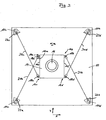
- the device comprises a table 10, which here has a square base with corresponding four corner regions 10a-d. In the corner regions 10a-d, in each case a bore 12 runs through the table. Approximately in the center is a receptacle 14 on the table, which has a cuboid shape with a square plan and whose four corners are marked 14a-d.
- a wafer 16 In a recess of the receptacle 14 is a wafer 16 to be positioned.
- hinges 18a-d which are pivotable along a plane parallel to the table 10, are arranged on opposite edges 14e, f of the receptacle 14.
- a rope 20a extends in the direction of the corner 10c of the table 10, where the rope 20a is guided around a deflection roller 22a through the associated opening 12 under the table 10, where it is around a further deflection roller 24a is guided to a drive unit 26a, in which the rope 22a can be motor-up or unwound.
- a line 28a extends to a computer 30th
- a cable 20b extends from an articulated arm 18bb in the direction of the corner 10d and runs via deflecting rollers 22b, 24b to a drive unit 26b, from which in turn a line 28b extends to the computer 30.
- the ropes 20a-d are stretched.
- the ropes 20a, 20b extend in a different direction (substantially opposite) to the ropes 20c, 20d.
- the course of the cables 20a, 20b is substantially mirror-inverted to the course of the cables 20c, 20d.
- the system is stable in itself.
- the position of the receptacle 14 relative to the table 10, however, can be adjusted, and thus position the wafer 16 in a desired manner, when now the drive units (such as 26a, 26b) are activated and thereby the corresponding cables 20a-d shortened or be extended (tracked).
- the drive units such as 26a, 26b
- the receptacle 14 can be moved both in the x and y directions.
- there is an angular displacement which is represented by the arrow ⁇ .
- the ropes 20a, 20d are tracked via the computer 30 and the associated drive units.
- a distance measuring system is provided which operates on a laser basis.
- a measuring system is associated with each cable 20a-d and is explained below by way of example for the cable 20a.
- a transmitter 32a is arranged, which transmits a laser beam to a receiver 34a, which is arranged above the articulated arm 18aa.
- the transmitter 32a is stationary, but pivotable (rotatable).
- the receiver 34a changes its position in accordance with the adjustment of the receptacle 14.
- the measuring device is also connected to the computer 30 via a line 36a.
- the exact alignment of the receptacle 14 and thus of the wafer 16 can be calculated in this way, continuously, during the adjustment and in the final final position ,
- an optical measuring device which indicates the exact position of the receptacle 14 on the table 10, could be arranged above the receptacle 14.
- the table 10 may be provided below the receptacle 14 with a plurality of capillary bores, which are connectable to a vacuum source in order to suck the receptacle 14 after reaching the desired end position stationary against the table can.
- an air cushion can be formed between the receptacle 14 and the table 10, for example in the manner of the so-called “Bernoulli effect", wherein the same capillaries can be used.
Landscapes
- Physics & Mathematics (AREA)
- General Physics & Mathematics (AREA)
- Container, Conveyance, Adherence, Positioning, Of Wafer (AREA)
- Exposure And Positioning Against Photoresist Photosensitive Materials (AREA)
- Registering Or Overturning Sheets (AREA)
- Valve Device For Special Equipments (AREA)
- Details Of Measuring And Other Instruments (AREA)
- Particle Accelerators (AREA)
- Vibration Prevention Devices (AREA)
- Manufacture, Treatment Of Glass Fibers (AREA)
Claims (16)
- Dispositif d'ajustage pour aligner un objet (16) dans un plan, avec les caractéristiques suivantes :1.1 une table (10),1.2 un logement (14) destiné à être positionné sur la table (10),1.3 le logement (14) étant réalisé pour la fixation amovible de l'objet (16) à positionner,1.4 au moins trois câbles (20a-d) qui, par l'intermédiaire d'articulations (18a-d, 18aa, 18bb) qui sont disposées entre les premières extrémités des câbles (20a-d) et le logement (14) et qui sont aptes à pivoter le long d'un plan parallèle à la table (10), sont articulés chacun avec une première extrémité contre des parties (14e, f) face à face du logement (14) et avec une deuxième extrémité contre la table (10),1.5 les câbles (20a-d) agissant dans au moins deux directions différentes (x, y, α).
- Dispositif d'ajustage selon la revendication 1, dans lequel les câbles (20a-d) sont agencés contre le logement (14) de manière articulée (18a-d), mais localement fixe.
- Dispositif d'ajustage selon la revendication 1, dans lequel les câbles (20a-d), entre leurs extrémités, sont guidés autour de poulies de renvoi (22a-d).
- Dispositif d'ajustage selon la revendication 1, dans lequel les premières extrémités des câbles (20a-d) sont situées dans la zone périphérique du logement (14).
- Dispositif d'ajustage selon la revendication 1, dans lequel les premières extrémités des câbles (20a-d) sont situées à une distance maximale les unes des autres.
- Dispositif d'ajustage selon la revendication 1 comportant trois câbles, dans lequel des lignes de liaison imaginaires décrivent un triangle entre leurs premières extrémités.
- Dispositif d'ajustage selon la revendication 1 comportant quatre câbles (20a-d), dans lequel des lignes de liaison imaginaires décrivent un rectangle entre leurs premières extrémités.
- Dispositif d'ajustage selon la revendication 7, dans lequel respectivement deux câbles (20a, b) sont disposés symétriquement à deux autres câbles (20c, d).
- Dispositif d'ajustage selon la revendication 7, dans lequel les lignes de liaison imaginaires décrivent un carré.
- Dispositif d'ajustage selon la revendication 1 comportant dans chaque cas un dispositif de mesure (32a, 34a), destiné à déterminer la position de chaque première extrémité des câbles (20a-d), et une unité d'analyse (30), destinée à déterminer la position du logement (14) sur la table (10).
- Dispositif d'ajustage selon la revendication 1 comportant un dispositif de mesure pour déterminer directement la position du logement (14) sur la table (10).
- Dispositif d'ajustage selon la revendication 1 comportant un dispositif pour positionner de manière localement fixe le logement (14) sur la table (10).
- Dispositif d'ajustage selon la revendication 12, dans lequel le dispositif est un dispositif destiné à fixer par aspiration le logement (14) sur la table (10).
- Dispositif d'ajustage selon la revendication 1 comportant des moyens pour la fixation amovible de l'objet (16) à positionner sur ou dans le logement (14).
- Dispositif d'ajustage selon la revendication 14, dans lequel les moyens comportent une unité d'aspiration destinée à fixer l'objet (16) sur ou dans le logement (14) sous l'effet d'une dépression.
- Dispositif d'ajustage selon la revendication 1, dans lequel des moyens de glissement sont disposés entre la table (10) et le logement (14).
Applications Claiming Priority (2)
| Application Number | Priority Date | Filing Date | Title |
|---|---|---|---|
| DE10359273 | 2003-12-17 | ||
| DE10359273A DE10359273A1 (de) | 2003-12-17 | 2003-12-17 | Justiervorrichtung |
Publications (3)
| Publication Number | Publication Date |
|---|---|
| EP1544911A2 EP1544911A2 (fr) | 2005-06-22 |
| EP1544911A3 EP1544911A3 (fr) | 2005-11-23 |
| EP1544911B1 true EP1544911B1 (fr) | 2007-07-25 |
Family
ID=34485441
Family Applications (1)
| Application Number | Title | Priority Date | Filing Date |
|---|---|---|---|
| EP04028528A Expired - Lifetime EP1544911B1 (fr) | 2003-12-17 | 2004-12-02 | Dispositif d'ajustage |
Country Status (4)
| Country | Link |
|---|---|
| US (1) | US7246445B2 (fr) |
| EP (1) | EP1544911B1 (fr) |
| AT (1) | ATE368300T1 (fr) |
| DE (2) | DE10359273A1 (fr) |
Families Citing this family (10)
| Publication number | Priority date | Publication date | Assignee | Title |
|---|---|---|---|---|
| US7898204B2 (en) * | 2007-01-05 | 2011-03-01 | Active Precision, Inc. | High-speed substrate manipulator |
| ES2484095T3 (es) * | 2010-05-27 | 2014-08-11 | Fundación Tecnalia Research & Innovation | Dispositivo de posicionamiento controlado por cables |
| CN106569396B (zh) * | 2011-09-12 | 2018-10-19 | 迈普尔平版印刷Ip有限公司 | 目标定位装置 |
| DE102013112188B4 (de) * | 2013-11-06 | 2017-08-03 | Carl Zeiss Industrielle Messtechnik Gmbh | Verfahren zur Montage von Bauteilen mit Hilfe eines Koordinatenmessgeräts |
| KR101627766B1 (ko) * | 2014-02-04 | 2016-06-07 | 전남대학교산학협력단 | 케이블 기반 병렬형 로봇을 위한 케이블 연결 위치 변경장치 |
| AU2015266576B2 (en) * | 2014-05-30 | 2019-11-21 | James Douglass PENN | Positioning system |
| US10449668B2 (en) * | 2014-12-19 | 2019-10-22 | Fundación Tecnalia Research & Innovation | Planar motion device |
| NL2016688A (en) * | 2015-07-09 | 2017-01-17 | Asml Netherlands Bv | Movable support and lithographic apparatus |
| US11121115B2 (en) * | 2018-09-20 | 2021-09-14 | Asm Technology Singapore Pte Ltd. | Y-theta table for semiconductor equipment |
| CN110817755A (zh) * | 2019-11-19 | 2020-02-21 | 西安电子科技大学 | 一种大范围立面作业索牵引平动运动平台及方法 |
Family Cites Families (22)
| Publication number | Priority date | Publication date | Assignee | Title |
|---|---|---|---|---|
| US3155383A (en) * | 1962-10-11 | 1964-11-03 | Link Division Of General Prec | Precision positioning apparatus |
| US3744902A (en) * | 1968-10-23 | 1973-07-10 | Siemens Ag | Device for producing a photo-varnish mask |
| US4346867A (en) * | 1978-07-05 | 1982-08-31 | Dick Donald E | Transport mechanism for ultrasonic scanner |
| US4575942A (en) * | 1982-10-18 | 1986-03-18 | Hitachi, Ltd. | Ultra-precision two-dimensional moving apparatus |
| US4524520A (en) * | 1983-02-24 | 1985-06-25 | Levy Nessim I | Carriage positioning system |
| US4600083A (en) * | 1984-09-06 | 1986-07-15 | Parent Christopher A | Positioning systems |
| JPS61270044A (ja) * | 1985-05-24 | 1986-11-29 | Toshiba Corp | 3軸移動ステ−ジ |
| US4993696A (en) * | 1986-12-01 | 1991-02-19 | Canon Kabushiki Kaisha | Movable stage mechanism |
| US5040431A (en) * | 1988-01-22 | 1991-08-20 | Canon Kabushiki Kaisha | Movement guiding mechanism |
| US5059090A (en) * | 1990-01-16 | 1991-10-22 | International Business Machines Corp. | Two-dimensional positioning apparatus |
| US5063676A (en) * | 1990-02-13 | 1991-11-12 | Gerber Garment Technology, Inc. | Cable drive system for carriage movement and method of use |
| US5140242A (en) * | 1990-04-30 | 1992-08-18 | International Business Machines Corporation | Servo guided stage system |
| JPH05228770A (ja) * | 1990-07-20 | 1993-09-07 | Nikotetsuku:Kk | 平面運動機構 |
| DE4345090C2 (de) | 1993-12-31 | 1995-11-23 | Perthen Feinpruef Gmbh | Drehtisch |
| US5585707A (en) * | 1994-02-28 | 1996-12-17 | Mcdonnell Douglas Corporation | Tendon suspended platform robot |
| DE4436320A1 (de) * | 1994-07-05 | 1996-01-11 | Otfried Urban | Positioniervorrichtung und/oder Meßvorrichtung |
| JP3557719B2 (ja) * | 1995-05-25 | 2004-08-25 | 日本精工株式会社 | 送り装置 |
| DE29907533U1 (de) | 1999-04-28 | 2000-09-21 | Belyakov, Vladimir K., Balaschicha | Gerät, insbesondere Arbeitstisch für einen Projektor |
| DE10011512B4 (de) * | 2000-03-09 | 2006-04-20 | Fraunhofer-Gesellschaft zur Förderung der angewandten Forschung e.V. | Werkzeugmaschine zur hochpräzisen räumlichen Anordnung eines Werkzeugs oder Werkstücks |
| DE10128713A1 (de) | 2001-06-13 | 2003-01-09 | Erich Thallner | Justiertisch |
| US6817104B2 (en) * | 2002-05-15 | 2004-11-16 | Sumitomo Heavy Industries, Ltd. | X-Y stage apparatus |
| JP2004223647A (ja) * | 2003-01-22 | 2004-08-12 | Nsk Ltd | 位置決め装置 |
-
2003
- 2003-12-17 DE DE10359273A patent/DE10359273A1/de not_active Withdrawn
-
2004
- 2004-12-02 DE DE502004004422T patent/DE502004004422D1/de not_active Expired - Lifetime
- 2004-12-02 EP EP04028528A patent/EP1544911B1/fr not_active Expired - Lifetime
- 2004-12-02 AT AT04028528T patent/ATE368300T1/de active
- 2004-12-16 US US11/013,734 patent/US7246445B2/en not_active Expired - Lifetime
Non-Patent Citations (1)
| Title |
|---|
| None * |
Also Published As
| Publication number | Publication date |
|---|---|
| US20050146169A1 (en) | 2005-07-07 |
| ATE368300T1 (de) | 2007-08-15 |
| US7246445B2 (en) | 2007-07-24 |
| EP1544911A2 (fr) | 2005-06-22 |
| DE502004004422D1 (de) | 2007-09-06 |
| EP1544911A3 (fr) | 2005-11-23 |
| DE10359273A1 (de) | 2005-07-21 |
Similar Documents
| Publication | Publication Date | Title |
|---|---|---|
| DE2556098C2 (de) | Vorrichtung zum Einsetzen eines Stiftes in ein Loch eines Werkstückes | |
| DE69632691T2 (de) | Flacher abtasttisch für rastersonden-mikroskopie | |
| DE4313719C2 (de) | Transportvorrichtung | |
| DE102007010224B4 (de) | Vorrichtung zum Haltern von scheibenförmigen Objekten | |
| CH643959A5 (de) | Verfahren und vorrichtung zur automatischen lageerkennung von halbleiterchips. | |
| DE19544299A1 (de) | Verfahren und Vorrichtung zum Vermessen von Strukturen | |
| EP1544911A2 (fr) | Dispositif d'ajustage | |
| EP1612032A1 (fr) | Dispositif pour aligner deux coquilles de moulage | |
| DE102012100609A1 (de) | Vorrichtung zum optischen Abtasten und Vermessen einer Umgebung | |
| DE102017103938A1 (de) | Vorrichtung zum Messen der Rauheit einer Werkstückoberfläche | |
| DE4446760C2 (de) | Vorrichtung zum Messen von Verformungen eines Gegenstandes | |
| EP3037371A1 (fr) | Dispositif et procede de reception, de maintien et/ou de manipulation d'objets plats | |
| WO2005075158A1 (fr) | Systeme de robot presentant des outils, une camera et une source lumineuse | |
| DE69117215T2 (de) | Rastertunnelmikroskop | |
| AT500030B1 (de) | Justiervorrichtung | |
| DE10254358A1 (de) | Positionsmessvorrichtung | |
| DE60216977T2 (de) | Positioniervorrichtung, insbesondere für offsetdruckplatten | |
| EP3086151B1 (fr) | Systeme et procede d'alignement d'un ecran par rapport a un axe optique | |
| DE102004017114A1 (de) | Vorrichtung zur Handhabung eines scheibenartigen Elements, insbesondere zur Handhabung eines Wafers | |
| DE10228818B4 (de) | Positioniertisch | |
| EP1115545A1 (fr) | Dispositif et procede pour le transfert de microstructures | |
| EP1588855A1 (fr) | Dispositif de mesure photoélectrique d'un document à mesurer et procédé de détermination des coordonnées d'une position sélectionnée sur un document à mesurer avec un tel dispositif de mesure | |
| DE60318175T2 (de) | Ausrichtung optischer Bauteile eines Messsystems | |
| DE102021107327B3 (de) | Kalottenvorrichtung und Verfahren zum Ausrichten eines Oberelements gegenüber einem Unterelement für eine Positioniervorrichtung und Positioniervorrichtung | |
| DE10011512A1 (de) | Werkzeugmaschine sowie Verfahren zur hochpräzisen räumlichen Anordnung eines Werkzeugs oder Werkstücks |
Legal Events
| Date | Code | Title | Description |
|---|---|---|---|
| PUAI | Public reference made under article 153(3) epc to a published international application that has entered the european phase |
Free format text: ORIGINAL CODE: 0009012 |
|
| AK | Designated contracting states |
Kind code of ref document: A2 Designated state(s): AT BE BG CH CY CZ DE DK EE ES FI FR GB GR HU IE IS IT LI LT LU MC NL PL PT RO SE SI SK TR |
|
| AX | Request for extension of the european patent |
Extension state: AL BA HR LV MK |
|
| PUAL | Search report despatched |
Free format text: ORIGINAL CODE: 0009013 |
|
| AK | Designated contracting states |
Kind code of ref document: A3 Designated state(s): AT BE BG CH CY CZ DE DK EE ES FI FR GB GR HU IE IS IT LI LT LU MC NL PL PT RO SE SI SK TR |
|
| AX | Request for extension of the european patent |
Extension state: AL BA HR LV MK |
|
| 17P | Request for examination filed |
Effective date: 20060323 |
|
| AKX | Designation fees paid |
Designated state(s): AT BE BG CH CY CZ DE DK EE ES FI FR GB GR HU IE IS IT LI LT LU MC NL PL PT RO SE SI SK TR |
|
| 17Q | First examination report despatched |
Effective date: 20060831 |
|
| GRAP | Despatch of communication of intention to grant a patent |
Free format text: ORIGINAL CODE: EPIDOSNIGR1 |
|
| GRAS | Grant fee paid |
Free format text: ORIGINAL CODE: EPIDOSNIGR3 |
|
| GRAA | (expected) grant |
Free format text: ORIGINAL CODE: 0009210 |
|
| AK | Designated contracting states |
Kind code of ref document: B1 Designated state(s): AT BE BG CH CY CZ DE DK EE ES FI FR GB GR HU IE IS IT LI LT LU MC NL PL PT RO SE SI SK TR |
|
| REG | Reference to a national code |
Ref country code: GB Ref legal event code: FG4D Free format text: NOT ENGLISH |
|
| REG | Reference to a national code |
Ref country code: CH Ref legal event code: EP |
|
| REG | Reference to a national code |
Ref country code: IE Ref legal event code: FG4D Free format text: LANGUAGE OF EP DOCUMENT: GERMAN |
|
| REF | Corresponds to: |
Ref document number: 502004004422 Country of ref document: DE Date of ref document: 20070906 Kind code of ref document: P |
|
| PG25 | Lapsed in a contracting state [announced via postgrant information from national office to epo] |
Ref country code: FI Free format text: LAPSE BECAUSE OF FAILURE TO SUBMIT A TRANSLATION OF THE DESCRIPTION OR TO PAY THE FEE WITHIN THE PRESCRIBED TIME-LIMIT Effective date: 20070725 Ref country code: PT Free format text: LAPSE BECAUSE OF FAILURE TO SUBMIT A TRANSLATION OF THE DESCRIPTION OR TO PAY THE FEE WITHIN THE PRESCRIBED TIME-LIMIT Effective date: 20071226 Ref country code: LT Free format text: LAPSE BECAUSE OF FAILURE TO SUBMIT A TRANSLATION OF THE DESCRIPTION OR TO PAY THE FEE WITHIN THE PRESCRIBED TIME-LIMIT Effective date: 20070725 Ref country code: IS Free format text: LAPSE BECAUSE OF FAILURE TO SUBMIT A TRANSLATION OF THE DESCRIPTION OR TO PAY THE FEE WITHIN THE PRESCRIBED TIME-LIMIT Effective date: 20071125 Ref country code: BG Free format text: LAPSE BECAUSE OF FAILURE TO SUBMIT A TRANSLATION OF THE DESCRIPTION OR TO PAY THE FEE WITHIN THE PRESCRIBED TIME-LIMIT Effective date: 20071025 Ref country code: NL Free format text: LAPSE BECAUSE OF FAILURE TO SUBMIT A TRANSLATION OF THE DESCRIPTION OR TO PAY THE FEE WITHIN THE PRESCRIBED TIME-LIMIT Effective date: 20070725 Ref country code: ES Free format text: LAPSE BECAUSE OF FAILURE TO SUBMIT A TRANSLATION OF THE DESCRIPTION OR TO PAY THE FEE WITHIN THE PRESCRIBED TIME-LIMIT Effective date: 20071105 |
|
| NLV1 | Nl: lapsed or annulled due to failure to fulfill the requirements of art. 29p and 29m of the patents act | ||
| GBV | Gb: ep patent (uk) treated as always having been void in accordance with gb section 77(7)/1977 [no translation filed] |
Effective date: 20070725 |
|
| PG25 | Lapsed in a contracting state [announced via postgrant information from national office to epo] |
Ref country code: PL Free format text: LAPSE BECAUSE OF FAILURE TO SUBMIT A TRANSLATION OF THE DESCRIPTION OR TO PAY THE FEE WITHIN THE PRESCRIBED TIME-LIMIT Effective date: 20070725 |
|
| REG | Reference to a national code |
Ref country code: IE Ref legal event code: FD4D |
|
| EN | Fr: translation not filed | ||
| PG25 | Lapsed in a contracting state [announced via postgrant information from national office to epo] |
Ref country code: GR Free format text: LAPSE BECAUSE OF FAILURE TO SUBMIT A TRANSLATION OF THE DESCRIPTION OR TO PAY THE FEE WITHIN THE PRESCRIBED TIME-LIMIT Effective date: 20071026 Ref country code: DK Free format text: LAPSE BECAUSE OF FAILURE TO SUBMIT A TRANSLATION OF THE DESCRIPTION OR TO PAY THE FEE WITHIN THE PRESCRIBED TIME-LIMIT Effective date: 20070725 |
|
| PG25 | Lapsed in a contracting state [announced via postgrant information from national office to epo] |
Ref country code: GB Free format text: LAPSE BECAUSE OF FAILURE TO SUBMIT A TRANSLATION OF THE DESCRIPTION OR TO PAY THE FEE WITHIN THE PRESCRIBED TIME-LIMIT Effective date: 20070725 Ref country code: CZ Free format text: LAPSE BECAUSE OF FAILURE TO SUBMIT A TRANSLATION OF THE DESCRIPTION OR TO PAY THE FEE WITHIN THE PRESCRIBED TIME-LIMIT Effective date: 20070725 Ref country code: IE Free format text: LAPSE BECAUSE OF FAILURE TO SUBMIT A TRANSLATION OF THE DESCRIPTION OR TO PAY THE FEE WITHIN THE PRESCRIBED TIME-LIMIT Effective date: 20070725 Ref country code: SK Free format text: LAPSE BECAUSE OF FAILURE TO SUBMIT A TRANSLATION OF THE DESCRIPTION OR TO PAY THE FEE WITHIN THE PRESCRIBED TIME-LIMIT Effective date: 20070725 |
|
| PLBE | No opposition filed within time limit |
Free format text: ORIGINAL CODE: 0009261 |
|
| STAA | Information on the status of an ep patent application or granted ep patent |
Free format text: STATUS: NO OPPOSITION FILED WITHIN TIME LIMIT |
|
| BERE | Be: lapsed |
Owner name: THALLNER, ERICH, DIPL.-ING. Effective date: 20071231 |
|
| PG25 | Lapsed in a contracting state [announced via postgrant information from national office to epo] |
Ref country code: SE Free format text: LAPSE BECAUSE OF FAILURE TO SUBMIT A TRANSLATION OF THE DESCRIPTION OR TO PAY THE FEE WITHIN THE PRESCRIBED TIME-LIMIT Effective date: 20071025 Ref country code: RO Free format text: LAPSE BECAUSE OF FAILURE TO SUBMIT A TRANSLATION OF THE DESCRIPTION OR TO PAY THE FEE WITHIN THE PRESCRIBED TIME-LIMIT Effective date: 20070725 |
|
| 26N | No opposition filed |
Effective date: 20080428 |
|
| PG25 | Lapsed in a contracting state [announced via postgrant information from national office to epo] |
Ref country code: MC Free format text: LAPSE BECAUSE OF NON-PAYMENT OF DUE FEES Effective date: 20071231 Ref country code: FR Free format text: LAPSE BECAUSE OF FAILURE TO SUBMIT A TRANSLATION OF THE DESCRIPTION OR TO PAY THE FEE WITHIN THE PRESCRIBED TIME-LIMIT Effective date: 20080321 |
|
| PG25 | Lapsed in a contracting state [announced via postgrant information from national office to epo] |
Ref country code: BE Free format text: LAPSE BECAUSE OF NON-PAYMENT OF DUE FEES Effective date: 20071231 |
|
| PG25 | Lapsed in a contracting state [announced via postgrant information from national office to epo] |
Ref country code: EE Free format text: LAPSE BECAUSE OF FAILURE TO SUBMIT A TRANSLATION OF THE DESCRIPTION OR TO PAY THE FEE WITHIN THE PRESCRIBED TIME-LIMIT Effective date: 20070725 |
|
| PG25 | Lapsed in a contracting state [announced via postgrant information from national office to epo] |
Ref country code: SI Free format text: LAPSE BECAUSE OF FAILURE TO SUBMIT A TRANSLATION OF THE DESCRIPTION OR TO PAY THE FEE WITHIN THE PRESCRIBED TIME-LIMIT Effective date: 20070725 |
|
| PG25 | Lapsed in a contracting state [announced via postgrant information from national office to epo] |
Ref country code: CY Free format text: LAPSE BECAUSE OF FAILURE TO SUBMIT A TRANSLATION OF THE DESCRIPTION OR TO PAY THE FEE WITHIN THE PRESCRIBED TIME-LIMIT Effective date: 20070725 |
|
| REG | Reference to a national code |
Ref country code: CH Ref legal event code: PL |
|
| PG25 | Lapsed in a contracting state [announced via postgrant information from national office to epo] |
Ref country code: LU Free format text: LAPSE BECAUSE OF NON-PAYMENT OF DUE FEES Effective date: 20071202 |
|
| PG25 | Lapsed in a contracting state [announced via postgrant information from national office to epo] |
Ref country code: HU Free format text: LAPSE BECAUSE OF FAILURE TO SUBMIT A TRANSLATION OF THE DESCRIPTION OR TO PAY THE FEE WITHIN THE PRESCRIBED TIME-LIMIT Effective date: 20080126 Ref country code: TR Free format text: LAPSE BECAUSE OF FAILURE TO SUBMIT A TRANSLATION OF THE DESCRIPTION OR TO PAY THE FEE WITHIN THE PRESCRIBED TIME-LIMIT Effective date: 20070725 |
|
| PG25 | Lapsed in a contracting state [announced via postgrant information from national office to epo] |
Ref country code: LI Free format text: LAPSE BECAUSE OF NON-PAYMENT OF DUE FEES Effective date: 20081231 Ref country code: CH Free format text: LAPSE BECAUSE OF NON-PAYMENT OF DUE FEES Effective date: 20081231 |
|
| PG25 | Lapsed in a contracting state [announced via postgrant information from national office to epo] |
Ref country code: IT Free format text: LAPSE BECAUSE OF NON-PAYMENT OF DUE FEES Effective date: 20071231 |
|
| PGFP | Annual fee paid to national office [announced via postgrant information from national office to epo] |
Ref country code: DE Payment date: 20231214 Year of fee payment: 20 Ref country code: AT Payment date: 20231214 Year of fee payment: 20 |
|
| REG | Reference to a national code |
Ref country code: DE Ref legal event code: R071 Ref document number: 502004004422 Country of ref document: DE |
|
| REG | Reference to a national code |
Ref country code: AT Ref legal event code: MK07 Ref document number: 368300 Country of ref document: AT Kind code of ref document: T Effective date: 20241202 |