EP1544846B1 - Schallabsorbierendes flächiges Schaumstoffmaterial - Google Patents
Schallabsorbierendes flächiges Schaumstoffmaterial Download PDFInfo
- Publication number
- EP1544846B1 EP1544846B1 EP20040029672 EP04029672A EP1544846B1 EP 1544846 B1 EP1544846 B1 EP 1544846B1 EP 20040029672 EP20040029672 EP 20040029672 EP 04029672 A EP04029672 A EP 04029672A EP 1544846 B1 EP1544846 B1 EP 1544846B1
- Authority
- EP
- European Patent Office
- Prior art keywords
- sound
- foam material
- layer
- elevations
- foam
- Prior art date
- Legal status (The legal status is an assumption and is not a legal conclusion. Google has not performed a legal analysis and makes no representation as to the accuracy of the status listed.)
- Expired - Lifetime
Links
- 239000006261 foam material Substances 0.000 title claims description 16
- 239000010410 layer Substances 0.000 claims description 28
- 239000006260 foam Substances 0.000 claims description 19
- 239000002344 surface layer Substances 0.000 claims description 8
- 238000007373 indentation Methods 0.000 claims description 2
- 238000010521 absorption reaction Methods 0.000 description 21
- 230000000694 effects Effects 0.000 description 8
- 239000006096 absorbing agent Substances 0.000 description 5
- 238000010586 diagram Methods 0.000 description 3
- 238000011038 discontinuous diafiltration by volume reduction Methods 0.000 description 3
- 239000011358 absorbing material Substances 0.000 description 2
- 229920002635 polyurethane Polymers 0.000 description 2
- 239000004814 polyurethane Substances 0.000 description 2
- QNRATNLHPGXHMA-XZHTYLCXSA-N (r)-(6-ethoxyquinolin-4-yl)-[(2s,4s,5r)-5-ethyl-1-azabicyclo[2.2.2]octan-2-yl]methanol;hydrochloride Chemical group Cl.C([C@H]([C@H](C1)CC)C2)CN1[C@@H]2[C@H](O)C1=CC=NC2=CC=C(OCC)C=C21 QNRATNLHPGXHMA-XZHTYLCXSA-N 0.000 description 1
- 229920005830 Polyurethane Foam Polymers 0.000 description 1
- 239000000853 adhesive Substances 0.000 description 1
- 238000004378 air conditioning Methods 0.000 description 1
- 239000002775 capsule Substances 0.000 description 1
- 238000005253 cladding Methods 0.000 description 1
- 238000002485 combustion reaction Methods 0.000 description 1
- 150000002148 esters Chemical class 0.000 description 1
- 239000007788 liquid Substances 0.000 description 1
- 239000000463 material Substances 0.000 description 1
- 239000012528 membrane Substances 0.000 description 1
- 238000012986 modification Methods 0.000 description 1
- 230000004048 modification Effects 0.000 description 1
- 230000010355 oscillation Effects 0.000 description 1
- 239000002245 particle Substances 0.000 description 1
- 239000011496 polyurethane foam Substances 0.000 description 1
- 239000012779 reinforcing material Substances 0.000 description 1
- XLYOFNOQVPJJNP-UHFFFAOYSA-N water Substances O XLYOFNOQVPJJNP-UHFFFAOYSA-N 0.000 description 1
Images


Classifications
-
- G—PHYSICS
- G10—MUSICAL INSTRUMENTS; ACOUSTICS
- G10K—SOUND-PRODUCING DEVICES; METHODS OR DEVICES FOR PROTECTING AGAINST, OR FOR DAMPING, NOISE OR OTHER ACOUSTIC WAVES IN GENERAL; ACOUSTICS NOT OTHERWISE PROVIDED FOR
- G10K11/00—Methods or devices for transmitting, conducting or directing sound in general; Methods or devices for protecting against, or for damping, noise or other acoustic waves in general
- G10K11/16—Methods or devices for protecting against, or for damping, noise or other acoustic waves in general
Definitions
- the invention relates to a sound-absorbing, sheet-like or layered foam material, in particular for lining soundproof hoods and housings, hoods and the like.
- the foam layer may have a microporous surface layer by fusing.
- the sound absorption effect of such foam linings depends, in addition to the material properties and structure of the absorber, above all on the thickness of the foam layer.
- DE 2 246 621 describes an acoustic panel with elevations and depressions.
- the purpose of sound absorption is to remove or absorb as much energy as possible from the incident sound wave.
- the highest energy level of a sound wave is in the range of the maximum amplitude, i. H. the vertical oscillation of the air particles perpendicular to the propagation direction, which is highest at ⁇ / 4 and 3 ⁇ 4 ⁇ .
- a porous absorber such as foam material
- a sound frequency of 1000 Hz resulting in consideration of the speed of sound, a wavelength of 0.33 m, the maximum amplitude at 8 or 24 cm occurs.
- Even with an ideal porous absorber that is less than 8 cm thick complete absorption can not be achieved. To reduce 99.9% of the sound at 100 Hz, the absorber thickness would have to be about 82 cm thick.
- the invention has for its object to significantly improve the sound absorption effect in a layered foam material without the layer thickness must be increased.
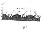
- Fig. 1 schematically shows a cross section through a layer 1 of polyurethane foam, which represents a porous absorber and has an average layer thickness of, for example, 15 mm.
- the back of the foam layer 1 facing away from the sound incidence, which comes into contact with a cladding wall, not shown, may be flat, while the surface facing the sound incidence is provided with mutually offset flat elevations 1 a and intermediate shallow recesses 1 b.
- the distance of the elevations 1a may be for example about 50 mm and the height difference to a recess 1b about 10 to 12 mm.
- Designated at 1c is a surface layer of the foam layer formed by fusing and burning about 2 to 3 mm of the foam material to the surface, for example, by unrolling a hot roll over the foam layer under pressure. This results in a largely closed surface of the combustion residues of the foam material, in particular polyurethane, but which is microporous.
- This surface layer 1c acts as a vibratable membrane and may have a thickness in the range of 10 to 15 ⁇ .
- This microporous surface layer or skin 1c is permeable to air, but not to water or oil, because of the surface tension of liquids.
- embossments are preferably provided which increase the surface for the incident sound and amplify diffraction effects of the sound.
- intersecting or diamond-shaped groove sections 1d are in FIG Fig. 1 indicated, which are embossed in the surface layer 1c and may have a depth of 1 to 3 mm.
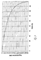
- Fig. 3 shows the absorption coefficient with diffuse sound incidence as a function of the frequency.
- All incidence angles occur in diffuse sound fields.
- the surface structure after Fig. 1 gives an optimal average angle of incidence. Due to the largely oblique sound incidence on the surface occur almost wall-parallel components of the sound amplitude, in which the longitudinal extent of the foam layer comes into effect, so that these components are effectively absorbed as by a very thick foam layer.
- sound absorption values are achieved which go beyond the purely by the layer thickness computationally achievable sound absorption effect significantly and otherwise can only be achieved with multiple layer thicknesses of a conventional sheet-like foam material.
- These high sound absorption values are supported by diffraction effects occurring at the indentations 1d, which are preferably provided in rhombic structure on the surface.
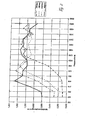
- Fig. 2 shows the degree of sound absorption of inventively designed foam layers at different average thickness dimensions as a function of the sound frequency. So it is at an average layer thickness of 30 mm and 630 Hz Absorption value ⁇ reached over 1.0, where 1.0 corresponds to 100%. For such an absorption value, a layer thickness of 130 mm is required for a foam layer of uniform thickness, that is to say without the wave structure of the microporous surface according to the invention.
- the practical significance of such absorption values is determined by the Fig. 4 and 5 clarified.
- Fig. 4 shows the sound level decrease as a function of the sound absorption coefficient ⁇ .
- Fig. 5 reflects the subjective perceived volume reduction. After that, z. For example, a sound level reduction of 5 dB at a sound level of 60 dB already represents a volume reduction for the human ear of 29%.
- the backside of the foam layer 1 may be coated with a reinforcing material. It may also be self-adhesive to facilitate attachment to a wall.
- the distance between the flat elevations 1a can be varied, as can the height between the elevation and the depression.
- the distance between the elevations 1a can be 40-60 mm, in particular 45-55 mm.
- the height between increase and depression can be 8 - 15 mm.
- a distance of the elevations of up to 100 mm can be used.
- a flat as possible surface structuring is provided in order to largely avoid the disadvantages of partially low volume density and thus poorer absorption.
- the wavy surface structure is independent of the layer thickness of the foam used.
- the wavy surface structure is designed so that at the lowest possible tread depth, an increase in surface area of about 180 - 250% is achieved.
- Fig. 1 with a spacing of the elevations of 50 mm and a difference between elevation and depression of 10 to 12 mm results in about a doubling of the surface or an increase in the surface of about 200%.
- the cutting line follows in Fig. 1 about a sine wave.
- the surface structure described leads to a significant improvement in the sound absorption effect in various types of foam material.
- the foam material used is polyurethane ester which has an approximately 40% open-cell and approximately 60% closed-cell structure.
Landscapes
- Physics & Mathematics (AREA)
- Engineering & Computer Science (AREA)
- Acoustics & Sound (AREA)
- Multimedia (AREA)
- Soundproofing, Sound Blocking, And Sound Damping (AREA)
- Vehicle Interior And Exterior Ornaments, Soundproofing, And Insulation (AREA)
- Laminated Bodies (AREA)
- Building Environments (AREA)
Description
- Die Erfindung betrifft ein schallabsorbierendes, flächiges bzw. schichtförmiges Schaumstoffmaterial, insbesondere zum Auskleiden von Schalldämmhauben und Einhausungen, Motorhauben und dergleichen.
- Es ist bekannt, für Auskleidungen von Schalldämmhauben und dergleichen eine Lage Schaumstoffmaterial zu verwenden. Die Schaumstoffschicht kann durch Anschmelzen eine mikroporöse Oberflächenschicht aufweisen. Die Schallabsorptionswirkung solcher Schaumstoffauskleidungen hängt neben Materialeigenschaften und Aufbau des Absorbers vor allem von der Dicke der Schaumstoffschicht ab.
-
DE 2 246 621 beschreibt eine Akustikplatte mit Erhöhungen und Vertiefungen. - Bei der Schallabsorption geht es darum, aus der einfallenden Schallwelle möglichst hohe Energieanteile abzuführen bzw. zu absorbieren. Die höchste Energieebene einer Schallwelle liegt im Bereich der maximalen Amplitude, d. h. der vertikalen Schwingung der Luftteilchen senkrecht zur Ausbreitungsrichtung, die bei λ/4 und ¾ λ am höchsten ist. Dies bedeutet für einen porösen Absorber wie Schaumstoffmaterial, dass für eine gute Wirkung der Schallabsorption umso höhere Schichtdicken benötigt werden, je niedriger die Schallfrequenz ist bzw. je größer die Wellenlänge der Schallwelle ist. Nimmt man beispielsweise eine Schallfrequenz von 1000 Hz, so ergibt sich unter Berücksichtigung der Schallgeschwindigkeit eine Wellenlänge von 0,33 m, wobei die maximale Amplitude bei 8 bzw. 24 cm auftritt. Selbst mit einem idealen porösen Absorber, der unter 8 cm dick ist, kann man keine vollständige Absorption erreichen. Um 99,9 % des Schalls bei 100 Hz abzubauen, müsste die Absorberdicke etwa 82 cm stark sein.
- In Motorkapseln, Maschinenverkleidungen, insbesondere im KFZ-Bereich, bei Klimakanälen und dergleichen ist es in der Regel nicht möglich, Schichtdicken des schallabsorbierenden Materials über 50 mm einzusetzen. Damit stellen die niedrigen, aber immer deutlich vorhandenen Frequenzbereiche < 1000 Hz unlösbare Probleme dar, weil die Schichtdicke nicht erhöht werden kann.
- Der Erfindung liegt die Aufgabe zugrunde, die Schallabsorptionswirkung bei einem schichtförmigen Schaumstoffmaterial deutlich zu verbessern, ohne dass die Schichtdicke erhöht werden muss.
- Diese Aufgabe wird, gemäß Anspruch 1 gelöst.
- Die Erfindung wird beispielsweise anhand der Zeichnung näher erläutert. Es zeigen
- Fig. 1
- eine Schnittansicht durch eine Schaumstoffschicht,
- Fig. 2
- ein Diagramm, das den Schallabsorptionsgrad in Abhängigkeit von der Schallfrequenz wiedergibt,
- Fig. 3
- ein Diagramm, das den Absorptionskoeffizienten in Abhängigkeit von der Frequenz bei einer Schaumstoffschicht wiedergibt,
- Fig. 4
- ein Diagramm, das die Pegelabnahme als Funktion des Schallabsorptionsgrads wiedergibt, und
- Fig. 5
- eine Tabelle, die die subjektiv empfundene Lautstärkenreduzierung wiedergibt.
-
Fig. 1 zeigt schematisch einen Querschnitt durch eine Schicht 1 aus Polyurethanschaum, die einen porösen Absorber darstellt und eine durchschnittliche Schichtdicke von beispielsweise 15 mm hat. Die dem Schalleinfall abgewandte Rückseite der Schaumstoffschicht 1, die an einer nicht dargestellten Verkleidungswand zum Anliegen kommt, kann eben ausgebildet sein, während die dem Schalleinfall zugewandte Oberfläche mit versetzt zueinander angeordneten flachen Erhöhungen 1a und dazwischen liegenden flachen Vertiefungen 1b versehen ist. Der Abstand der Erhöhungen 1a kann beispielsweise etwa 50 mm betragen und die Höhendifferenz zu einer Vertiefung 1b ca. 10 bis 12 mm. Durch diese Oberflächenstruktur ergibt sich gegenüber einer Schaumstoffschicht von 15 mm Dicke mit ebener Oberfläche etwa eine Verdoppelung der Schallschluckfläche. - Mit 1c ist eine Oberflächenschicht der Schaumstoffschicht bezeichnet, die durch Anschmelzen und Verbrennen von etwa 2 bis 3 mm des Schaumstoffinaterials an der Oberfläche ausgebildet wird, beispielsweise indem eine heiße Walze unter Druck über die Schaumstoffschicht abgerollt wird. Hierdurch ergibt sich eine weitgehend geschlossene Oberfläche aus den Verbrennungsrückständen des Schaumstoffmaterials, insbesondere Polyurethan, die aber mikroporös ist. Diese Oberflächenschicht 1c wirkt als schwingungsfähige Membran und kann eine Dicke im Bereich von 10 bis 15 µ haben.
- Diese mikroporöse Oberflächenschicht bzw. Haut 1c ist für Luft durchlässig, nicht aber für Wasser oder Öl, wegen der Oberflächenspannung von Flüssigkeiten.
- In der Oberflächenschicht 1c werden vorzugsweise Einprägungen vorgesehen, die die Oberfläche für den einfallenden Schall vergrößern und Beugungseffekte des Schalls verstärken. Als Beispiel sind sich kreuzende bzw. rautenförmig angeordnete Nutabschnitte 1d in
Fig. 1 angedeutet, die in die Oberflächenschicht 1c eingeprägt sind und eine Tiefe von 1 bis 3 mm haben können. - Die Absorption eines Schallschluckmaterials hängt auch sehr stark vom Einfallswinkel einer Schallwelle ab.
Fig. 3 zeigt den Absorptionskoeffizienten bei diffusem Schalleinfall in Abhängigkeit von der Frequenz. In der Praxis treten bei diffusen Schallfeldern alle Einfallswinkel auf. Die Oberflächenstruktur nachFig. 1 ergibt einen optimalen durchschnittlichen Einfallswinkel. Durch den zum großen Teil schrägen Schalleinfall auf die Oberfläche treten nahezu wandparallele Komponenten der Schallamplitude auf, bei denen die Längsausdehnung der Schaumstoffschicht zur Wirkung kommt, so dass diese Komponenten wie durch eine sehr dicke Schaumstofflage wirksam absorbiert werden. Hierdurch werden Schallabsorptionswerte erzielt, die über die allein durch die Schichtdicke rechnerisch erzielbare Schallabsorptionswirkung deutlich hinausgehen und sonst nur mit vielfachen Schichtdicken eines üblichen flächigen Schaumstoffmaterials erreicht werden. Diese hohen Schallabsorptionswerte werden unterstützt durch auftretende Beugungseffekte an den Einprägungen 1d, die vorzugsweise in Rautenstruktur an der Oberfläche vorgesehen sind. -
Fig. 2 zeigt den Schallabsorptionsgrad von erfindungsgemäß gestalteten Schaumstoffschichten bei unterschiedlichen durchschnittlichen Dickenabmessungen in Abhängigkeit von der Schallfrequenz. So wird bei einer durchschnittlichen Schichtdicke von 30 mm und 630 Hz ein Absorptionswert α über 1,0 erreicht, wobei 1,0 100 % entspricht. Für einen solchen Absorptionswert wird bei einer Schaumstoffschicht einheitlicher Dicke, also ohne die erfindungsgemäße Wellenstruktur der mikroporösen Oberfläche, eine Schichtdicke von 130 mm benötigt. Die praktische Bedeutung derartiger Absorptionswerte wird durch dieFig. 4 und5 verdeutlicht.Fig. 4 zeigt die Schallpegelabnahme als Funktion des Schallabsorptionsgrads α.Fig. 5 gibt die subjektiv empfundene Lautstärkenreduzierung wieder. Danach entspricht z. B. eine Schallpegelreduzierung von 5 dB bei einem Schallpegel von 60 dB bereits einer Lautstärkenreduzierung für das menschliche Ohr von 29 %. - Die Rückseite der Schaumstoffschicht 1 kann mit einem Verstärkungsmaterial beschichtet sein. Sie kann auch selbstklebend ausgebildet sein, um die Anbringung an einer Wand zu erleichtem.
- Es sind verschiedene Abwandlungen der beschriebenen Gestaltung der Oberfläche einer Schaumstoffschicht möglich. So kann der Abstand der flachen Erhöhungen 1a variiert werden, wie auch die Höhe zwischen Erhöhung und Vertiefung. So kann der Abstand zwischen den Erhöhungen 1a 40 - 60 mm, insbesondere 45 - 55 mm betragen. Die Höhe zwischen Erhöhung und Vertiefung kann dabei 8 - 15 mm betragen. In besonderen Fällen kann ein Abstand der Erhöhungen von bis zu 100 mm verwendet werden. Insgesamt wird eine möglichst flache Oberflächenstrukturierung vorgesehen, um die Nachteile partiell geringer Volumendichte und damit schlechterer Absorption weitgehend zu vermeiden.
- Die wellenförmige Oberflächenstruktur ist unabhängig von der verwendeten Schichtdicke des Schaumstoffs. Bei einer gegebenen Dicke der Schaumstoffschicht wird die wellige Oberflächenstruktur so ausgelegt, dass bei geringst möglicher Profiltiefe eine Vergrößerung der Oberfläche von etwa 180 - 250 % erzielt wird. Bei dem Ausführungsbeispiel nach
Fig. 1 mit einem Abstand der Erhöhungen von 50 mm und einer Differenz zwischen Erhöhung und Vertiefung von 10 bis 12 mm ergibt sich etwa eine Verdoppelung der Oberfläche bzw. eine Erhöhung der Oberfläche von etw 200 %. - Bei dem dargestellten Ausführungsbeispiel folgt die Schnittlinie in
Fig. 1 etwa einer Sinuskurve. Es ist aber auch möglich, die Vertiefungen beispielsweise tiefer auszubilden und die Erhöhungen breiter zu gestalten als die Vertiefungen. Wesentlich ist hierbei, dass sich flache kuppenförmige Erhöhungen 1a ergeben und auch die Vertiefungen 1b derart flach abgerundet konkav gestaltet sind, dass sich eine stetige Neigungsänderung der Oberfläche ergibt. - Die beschriebene Oberflächenstruktur führt bei verschiedenen Arten von Schaumstoffmaterial zu einer wesentlichen Verbesserung der Schallabsorptionswirkung.
- Durch die eingeprägten Nutabschnitte 1d in der Oberflächenschicht wird deren mikroporöse Struktur im Bereich der Nuten 1d etwas offener, sodass höhere Frequenzen besser aufgenommen und absorbiert werden können.
- Vorzugsweise wird als Schaumstoffmaterial Polyurethan ester verwendet, der eine etwa 40 % offenzellige und etwa 60 % geschlossenzellige Struktur hat.
Claims (5)
- Schallabsoibieiendes, schichtfözmiges Schaumstoffmaterial, dessen dem Schalleinfall zugewandte Oberfläche mit Erhöhungen (1a) und Vertiefungen (1b) derart versehen ist, dass im Verhältnis zu einer Schaumstoffschicht von einheitlicher Dicke und gleichem Volumen pro Flächeneinheit die Oberfläche für den einfallenden Schall etwa auf zumindest das Doppelte vergrößert ist, wobei das Schaumstoffmaterial, der den Schalleinfall zugewandten Oberfläche eine mikroporöse Oberflächenschicht (1c) aufweist.
- SchaumstoSmaterial nach Anspruch 1, wobei die Oberfläche um etwa 180 - 250 % gegenüber einer ebenen Oberfläche durch flache Erhöhungen vergrößert ist.
- Schaumstoffmaterial nach Anspruch 1 oder 2, wobei im Querschnitt den Schaumstoffschicht (1) die Oberfläche eine wellenfözmige Struktur hat und in den Iälein der Schnittlinie versetzt dazu Erhöhungen einer benachbarten Schnittlinie angeordnet sind
- Schaumstoffmaterial nach Anspruch 3, wobei die Erhöhungen (1a) einen Abstand von etwa 40 - 60 mm von einander haben und die Höhe zwischen Erhöhung und Veitiefung etwa 8 - 15 mm beträgt.
- Schaumstoffmaterial nach einem der vorhergehenden Ansprüche, wobei die Oberfläche mit Einprägungen, wie rautenförmig angeordneten Nutabschnitten (1d) oder kleineren Vertiefungen versehen ist
Priority Applications (1)
| Application Number | Priority Date | Filing Date | Title |
|---|---|---|---|
| PL04029672T PL1544846T3 (pl) | 2003-12-15 | 2004-12-15 | Pochłaniający dźwięk płaski materiał z tworzywa piankowego |
Applications Claiming Priority (2)
| Application Number | Priority Date | Filing Date | Title |
|---|---|---|---|
| DE10358595A DE10358595A1 (de) | 2003-12-15 | 2003-12-15 | Schallabsorbierendes flächiges Schaumstoffmaterial |
| DE10358595 | 2003-12-15 |
Publications (3)
| Publication Number | Publication Date |
|---|---|
| EP1544846A2 EP1544846A2 (de) | 2005-06-22 |
| EP1544846A3 EP1544846A3 (de) | 2012-11-28 |
| EP1544846B1 true EP1544846B1 (de) | 2015-04-22 |
Family
ID=34485379
Family Applications (1)
| Application Number | Title | Priority Date | Filing Date |
|---|---|---|---|
| EP20040029672 Expired - Lifetime EP1544846B1 (de) | 2003-12-15 | 2004-12-15 | Schallabsorbierendes flächiges Schaumstoffmaterial |
Country Status (7)
| Country | Link |
|---|---|
| EP (1) | EP1544846B1 (de) |
| DE (1) | DE10358595A1 (de) |
| DK (1) | DK1544846T3 (de) |
| ES (1) | ES2543083T3 (de) |
| HU (1) | HUE025109T2 (de) |
| PL (1) | PL1544846T3 (de) |
| PT (1) | PT1544846E (de) |
Families Citing this family (1)
| Publication number | Priority date | Publication date | Assignee | Title |
|---|---|---|---|---|
| CN108231053A (zh) * | 2018-03-13 | 2018-06-29 | 吉林大学 | 一种具有凸包形态的声学包装材料及其制备方法 |
Family Cites Families (4)
| Publication number | Priority date | Publication date | Assignee | Title |
|---|---|---|---|---|
| DE2246621A1 (de) * | 1972-09-22 | 1974-03-28 | Albert Schrey | Akustikplatte |
| DE2915823A1 (de) * | 1979-04-19 | 1980-11-06 | Irbit Holding Ag | Schall-daemmplatte |
| DE3219339C1 (de) * | 1982-05-22 | 1983-02-03 | Metzeler Schaum Gmbh, 8940 Memmingen | Flaechiges Element zur Luftschall-Absorption |
| DE3313001A1 (de) * | 1983-04-12 | 1984-10-18 | Volkswagenwerk Ag, 3180 Wolfsburg | Schallabsorbierende schicht |
-
2003
- 2003-12-15 DE DE10358595A patent/DE10358595A1/de not_active Withdrawn
-
2004
- 2004-12-15 PL PL04029672T patent/PL1544846T3/pl unknown
- 2004-12-15 ES ES04029672.5T patent/ES2543083T3/es not_active Expired - Lifetime
- 2004-12-15 PT PT40296725T patent/PT1544846E/pt unknown
- 2004-12-15 EP EP20040029672 patent/EP1544846B1/de not_active Expired - Lifetime
- 2004-12-15 DK DK04029672.5T patent/DK1544846T3/en active
- 2004-12-15 HU HUE04029672A patent/HUE025109T2/en unknown
Also Published As
| Publication number | Publication date |
|---|---|
| DE10358595A1 (de) | 2005-07-21 |
| DK1544846T3 (en) | 2015-07-27 |
| PT1544846E (pt) | 2015-09-14 |
| EP1544846A2 (de) | 2005-06-22 |
| ES2543083T3 (es) | 2015-08-14 |
| PL1544846T3 (pl) | 2015-10-30 |
| EP1544846A3 (de) | 2012-11-28 |
| HUE025109T2 (en) | 2016-01-28 |
Similar Documents
| Publication | Publication Date | Title |
|---|---|---|
| DE2408028C3 (de) | ||
| DE112005003232B4 (de) | Schallschluckende Struktur | |
| EP2937483B1 (de) | Bauplatte, insbesondere wand- oder deckenplatte | |
| EP0131616B1 (de) | Schallabsorptionsplatte | |
| EP2203728B1 (de) | Schallabsorber | |
| WO1999040567A1 (de) | Flächenabsorber für schallwellen | |
| DD150917A5 (de) | Schallabsorbierendes bauelement aus kunststoff-folie | |
| DE10253832A1 (de) | Schallisolierender Hitzeschutzschild | |
| DE8700264U1 (de) | Aus Schaumstoff bestehende Schalldämmplatte | |
| DE19861016C2 (de) | Strukturierte Formkörper zur Schallabsorption | |
| DE602004002864T2 (de) | Bauteil zur geräuschmindenderung, insbesondere bodenplatte eines fahrzeuges | |
| DE3536379A1 (de) | Luftfuehrungskanal, insbesondere in kraftfahrzeugen | |
| DE20316050U1 (de) | Schallabsorbierender Hitzeschild | |
| DE2758041C2 (de) | Verwendung eines aus mindestens zwei übereinander angeordneten Folien, insbesondere Kunststoffolien, bestehenden Bauelements | |
| EP0683480B1 (de) | Schallabsorber | |
| EP1544846B1 (de) | Schallabsorbierendes flächiges Schaumstoffmaterial | |
| EP0742322B1 (de) | Schalldämpfungsvorrichtung | |
| DE29815712U1 (de) | Schallabsorber | |
| EP3246479B1 (de) | Absorbereinheit zum absorbieren von schall | |
| EP2575127B1 (de) | Schallabsorptionselement | |
| EP3310965B1 (de) | Schallabsorbierendes bauelement und schallschutzwand mit einem solchen bauelement | |
| DE3506488A1 (de) | Geraeuschdaemmender schichtkoerper | |
| DE4206615C2 (de) | Schallschluckende Bauplatte | |
| DE2437947A1 (de) | Anordnung zur absorption von luftschall | |
| EP3555370B1 (de) | Schallabsorbierendes bauelement mit löschungsprofilen sowie schallschutzwand |
Legal Events
| Date | Code | Title | Description |
|---|---|---|---|
| PUAI | Public reference made under article 153(3) epc to a published international application that has entered the european phase |
Free format text: ORIGINAL CODE: 0009012 |
|
| AK | Designated contracting states |
Kind code of ref document: A2 Designated state(s): AT BE BG CH CY CZ DE DK EE ES FI FR GB GR HU IE IS IT LI LT LU MC NL PL PT RO SE SI SK TR |
|
| AX | Request for extension of the european patent |
Extension state: AL BA HR LV MK YU |
|
| PUAL | Search report despatched |
Free format text: ORIGINAL CODE: 0009013 |
|
| AK | Designated contracting states |
Kind code of ref document: A3 Designated state(s): AT BE BG CH CY CZ DE DK EE ES FI FR GB GR HU IE IS IT LI LT LU MC NL PL PT RO SE SI SK TR |
|
| AX | Request for extension of the european patent |
Extension state: AL BA HR LV MK YU |
|
| RIC1 | Information provided on ipc code assigned before grant |
Ipc: G10K 11/16 20060101AFI20121024BHEP |
|
| 17P | Request for examination filed |
Effective date: 20130404 |
|
| AKX | Designation fees paid |
Designated state(s): AT BE BG CH CY CZ DE DK EE ES FI FR GB GR HU IE IS IT LI LT LU MC NL PL PT RO SE SI SK TR |
|
| GRAP | Despatch of communication of intention to grant a patent |
Free format text: ORIGINAL CODE: EPIDOSNIGR1 |
|
| INTG | Intention to grant announced |
Effective date: 20141113 |
|
| GRAS | Grant fee paid |
Free format text: ORIGINAL CODE: EPIDOSNIGR3 |
|
| GRAA | (expected) grant |
Free format text: ORIGINAL CODE: 0009210 |
|
| AK | Designated contracting states |
Kind code of ref document: B1 Designated state(s): AT BE BG CH CY CZ DE DK EE ES FI FR GB GR HU IE IS IT LI LT LU MC NL PL PT RO SE SI SK TR |
|
| REG | Reference to a national code |
Ref country code: GB Ref legal event code: FG4D Free format text: NOT ENGLISH |
|
| REG | Reference to a national code |
Ref country code: CH Ref legal event code: EP |
|
| REG | Reference to a national code |
Ref country code: AT Ref legal event code: REF Ref document number: 723651 Country of ref document: AT Kind code of ref document: T Effective date: 20150515 |
|
| REG | Reference to a national code |
Ref country code: IE Ref legal event code: FG4D Free format text: LANGUAGE OF EP DOCUMENT: GERMAN |
|
| REG | Reference to a national code |
Ref country code: DE Ref legal event code: R096 Ref document number: 502004014889 Country of ref document: DE Effective date: 20150603 |
|
| REG | Reference to a national code |
Ref country code: DK Ref legal event code: T3 Effective date: 20150723 |
|
| REG | Reference to a national code |
Ref country code: SE Ref legal event code: TRGR |
|
| REG | Reference to a national code |
Ref country code: NL Ref legal event code: T3 |
|
| REG | Reference to a national code |
Ref country code: ES Ref legal event code: FG2A Ref document number: 2543083 Country of ref document: ES Kind code of ref document: T3 Effective date: 20150814 |
|
| REG | Reference to a national code |
Ref country code: PT Ref legal event code: SC4A Free format text: AVAILABILITY OF NATIONAL TRANSLATION Effective date: 20150721 |
|
| REG | Reference to a national code |
Ref country code: LT Ref legal event code: MG4D |
|
| PG25 | Lapsed in a contracting state [announced via postgrant information from national office to epo] |
Ref country code: FI Free format text: LAPSE BECAUSE OF FAILURE TO SUBMIT A TRANSLATION OF THE DESCRIPTION OR TO PAY THE FEE WITHIN THE PRESCRIBED TIME-LIMIT Effective date: 20150422 Ref country code: LT Free format text: LAPSE BECAUSE OF FAILURE TO SUBMIT A TRANSLATION OF THE DESCRIPTION OR TO PAY THE FEE WITHIN THE PRESCRIBED TIME-LIMIT Effective date: 20150422 |
|
| REG | Reference to a national code |
Ref country code: PL Ref legal event code: T3 |
|
| PG25 | Lapsed in a contracting state [announced via postgrant information from national office to epo] |
Ref country code: GR Free format text: LAPSE BECAUSE OF FAILURE TO SUBMIT A TRANSLATION OF THE DESCRIPTION OR TO PAY THE FEE WITHIN THE PRESCRIBED TIME-LIMIT Effective date: 20150723 Ref country code: IS Free format text: LAPSE BECAUSE OF FAILURE TO SUBMIT A TRANSLATION OF THE DESCRIPTION OR TO PAY THE FEE WITHIN THE PRESCRIBED TIME-LIMIT Effective date: 20150822 |
|
| REG | Reference to a national code |
Ref country code: DE Ref legal event code: R097 Ref document number: 502004014889 Country of ref document: DE |
|
| REG | Reference to a national code |
Ref country code: HU Ref legal event code: AG4A Ref document number: E025109 Country of ref document: HU |
|
| PG25 | Lapsed in a contracting state [announced via postgrant information from national office to epo] |
Ref country code: EE Free format text: LAPSE BECAUSE OF FAILURE TO SUBMIT A TRANSLATION OF THE DESCRIPTION OR TO PAY THE FEE WITHIN THE PRESCRIBED TIME-LIMIT Effective date: 20150422 |
|
| PLBE | No opposition filed within time limit |
Free format text: ORIGINAL CODE: 0009261 |
|
| STAA | Information on the status of an ep patent application or granted ep patent |
Free format text: STATUS: NO OPPOSITION FILED WITHIN TIME LIMIT |
|
| PG25 | Lapsed in a contracting state [announced via postgrant information from national office to epo] |
Ref country code: RO Free format text: LAPSE BECAUSE OF NON-PAYMENT OF DUE FEES Effective date: 20150422 Ref country code: SK Free format text: LAPSE BECAUSE OF FAILURE TO SUBMIT A TRANSLATION OF THE DESCRIPTION OR TO PAY THE FEE WITHIN THE PRESCRIBED TIME-LIMIT Effective date: 20150422 |
|
| 26N | No opposition filed |
Effective date: 20160125 |
|
| PG25 | Lapsed in a contracting state [announced via postgrant information from national office to epo] |
Ref country code: SI Free format text: LAPSE BECAUSE OF FAILURE TO SUBMIT A TRANSLATION OF THE DESCRIPTION OR TO PAY THE FEE WITHIN THE PRESCRIBED TIME-LIMIT Effective date: 20150422 Ref country code: BE Free format text: LAPSE BECAUSE OF NON-PAYMENT OF DUE FEES Effective date: 20151231 |
|
| REG | Reference to a national code |
Ref country code: DK Ref legal event code: EBP Effective date: 20151231 |
|
| PG25 | Lapsed in a contracting state [announced via postgrant information from national office to epo] |
Ref country code: MC Free format text: LAPSE BECAUSE OF FAILURE TO SUBMIT A TRANSLATION OF THE DESCRIPTION OR TO PAY THE FEE WITHIN THE PRESCRIBED TIME-LIMIT Effective date: 20150422 Ref country code: LU Free format text: LAPSE BECAUSE OF FAILURE TO SUBMIT A TRANSLATION OF THE DESCRIPTION OR TO PAY THE FEE WITHIN THE PRESCRIBED TIME-LIMIT Effective date: 20151215 Ref country code: CZ Free format text: LAPSE BECAUSE OF NON-PAYMENT OF DUE FEES Effective date: 20151215 |
|
| REG | Reference to a national code |
Ref country code: CH Ref legal event code: PL |
|
| REG | Reference to a national code |
Ref country code: SE Ref legal event code: EUG |
|
| GBPC | Gb: european patent ceased through non-payment of renewal fee |
Effective date: 20151215 |
|
| PG25 | Lapsed in a contracting state [announced via postgrant information from national office to epo] |
Ref country code: SE Free format text: LAPSE BECAUSE OF NON-PAYMENT OF DUE FEES Effective date: 20151216 |
|
| REG | Reference to a national code |
Ref country code: NL Ref legal event code: MM Effective date: 20160101 |
|
| REG | Reference to a national code |
Ref country code: IE Ref legal event code: MM4A |
|
| REG | Reference to a national code |
Ref country code: FR Ref legal event code: ST Effective date: 20160831 |
|
| PG25 | Lapsed in a contracting state [announced via postgrant information from national office to epo] |
Ref country code: LI Free format text: LAPSE BECAUSE OF NON-PAYMENT OF DUE FEES Effective date: 20151231 Ref country code: GB Free format text: LAPSE BECAUSE OF NON-PAYMENT OF DUE FEES Effective date: 20151215 Ref country code: IE Free format text: LAPSE BECAUSE OF NON-PAYMENT OF DUE FEES Effective date: 20151215 Ref country code: NL Free format text: LAPSE BECAUSE OF NON-PAYMENT OF DUE FEES Effective date: 20160101 Ref country code: CH Free format text: LAPSE BECAUSE OF NON-PAYMENT OF DUE FEES Effective date: 20151231 Ref country code: HU Free format text: LAPSE BECAUSE OF NON-PAYMENT OF DUE FEES Effective date: 20151216 |
|
| PG25 | Lapsed in a contracting state [announced via postgrant information from national office to epo] |
Ref country code: FR Free format text: LAPSE BECAUSE OF NON-PAYMENT OF DUE FEES Effective date: 20151231 Ref country code: PT Free format text: LAPSE BECAUSE OF NON-PAYMENT OF DUE FEES Effective date: 20160915 |
|
| REG | Reference to a national code |
Ref country code: ES Ref legal event code: FD2A Effective date: 20170127 |
|
| PG25 | Lapsed in a contracting state [announced via postgrant information from national office to epo] |
Ref country code: DK Free format text: LAPSE BECAUSE OF NON-PAYMENT OF DUE FEES Effective date: 20151231 |
|
| REG | Reference to a national code |
Ref country code: AT Ref legal event code: MM01 Ref document number: 723651 Country of ref document: AT Kind code of ref document: T Effective date: 20151215 |
|
| PG25 | Lapsed in a contracting state [announced via postgrant information from national office to epo] |
Ref country code: PL Free format text: LAPSE BECAUSE OF NON-PAYMENT OF DUE FEES Effective date: 20151215 Ref country code: IT Free format text: LAPSE BECAUSE OF NON-PAYMENT OF DUE FEES Effective date: 20151215 Ref country code: ES Free format text: LAPSE BECAUSE OF NON-PAYMENT OF DUE FEES Effective date: 20151216 |
|
| PG25 | Lapsed in a contracting state [announced via postgrant information from national office to epo] |
Ref country code: AT Free format text: LAPSE BECAUSE OF NON-PAYMENT OF DUE FEES Effective date: 20151215 Ref country code: BG Free format text: LAPSE BECAUSE OF FAILURE TO SUBMIT A TRANSLATION OF THE DESCRIPTION OR TO PAY THE FEE WITHIN THE PRESCRIBED TIME-LIMIT Effective date: 20150422 |
|
| PG25 | Lapsed in a contracting state [announced via postgrant information from national office to epo] |
Ref country code: CY Free format text: LAPSE BECAUSE OF FAILURE TO SUBMIT A TRANSLATION OF THE DESCRIPTION OR TO PAY THE FEE WITHIN THE PRESCRIBED TIME-LIMIT Effective date: 20150422 |
|
| P01 | Opt-out of the competence of the unified patent court (upc) registered |
Effective date: 20230607 |
|
| PGFP | Annual fee paid to national office [announced via postgrant information from national office to epo] |
Ref country code: DE Payment date: 20231208 Year of fee payment: 20 |
|
| PG25 | Lapsed in a contracting state [announced via postgrant information from national office to epo] |
Ref country code: TR Free format text: LAPSE BECAUSE OF NON-PAYMENT OF DUE FEES Effective date: 20151215 |
|
| REG | Reference to a national code |
Ref country code: DE Ref legal event code: R071 Ref document number: 502004014889 Country of ref document: DE |