EP1544726A1 - Random number generator and random number generation method - Google Patents
Random number generator and random number generation method Download PDFInfo
- Publication number
- EP1544726A1 EP1544726A1 EP03788003A EP03788003A EP1544726A1 EP 1544726 A1 EP1544726 A1 EP 1544726A1 EP 03788003 A EP03788003 A EP 03788003A EP 03788003 A EP03788003 A EP 03788003A EP 1544726 A1 EP1544726 A1 EP 1544726A1
- Authority
- EP
- European Patent Office
- Prior art keywords
- random
- pulse
- generating
- noise
- thermal
- Prior art date
- Legal status (The legal status is an assumption and is not a legal conclusion. Google has not performed a legal analysis and makes no representation as to the accuracy of the status listed.)
- Granted
Links
Images




Classifications
-
- G—PHYSICS
- G06—COMPUTING OR CALCULATING; COUNTING
- G06F—ELECTRIC DIGITAL DATA PROCESSING
- G06F1/00—Details not covered by groups G06F3/00 - G06F13/00 and G06F21/00
- G06F1/02—Digital function generators
-
- G—PHYSICS
- G06—COMPUTING OR CALCULATING; COUNTING
- G06F—ELECTRIC DIGITAL DATA PROCESSING
- G06F7/00—Methods or arrangements for processing data by operating upon the order or content of the data handled
- G06F7/58—Random or pseudo-random number generators
- G06F7/588—Random number generators, i.e. based on natural stochastic processes
Definitions
- the present invention relates to an apparatus and method for generating physical random numbers in accordance with thermal noises to be randomly generated by a thermal-noise generating element comprising a resistor, a semiconductor or a conductor, or in accordance with light-based noises to be randomly generated by a light-emitting element, such as a LED or a PIN diode.
- thermal-noise generating element As one of methods for producing physical random numbers based on a natural phenomenon, there has been known a method using a resistor, a semiconductor such as a diode, or a conductor as a thermal-noise generating element. Thermal noises generated from the thermal-noise generating element are random in terms of both generation frequency and amplitude, and thereby physical random numbers can be produced in accordance with the thermal noises.
- Various random-number generating apparatuses utilizing such a thermal-noise generating element are disclosed in a number of publications.
- the most typical method for generating physical random numbers by use of a thermal-noise generating element comprises amplifying and sampling thermal noises output from a thermal-noise generating element at a certain moment, and comparing each of the sampled values with a given threshold to produce random numbers. Specifically, thermal noises output from a thermal-noise generating element are amplified and sampled in constant periods. Then, physical random numbers can be produced in a digital manner according to a predetermined rule that "1" will be assigned to the sampled value if it is greater than a given threshold, and "0" will be assigned to the sampled value if it is not greater than the threshold.
- This random-number generating apparatus comprises a first circuit for amplifying a thermal noise output from a thermal-noise generating element and generating a rectangular pulse which rises at the moment when the height of the pulse exceeds a given threshold, a second circuit for generating clocks having a substantially higher frequency than that of the pulse, and a counter for counting the clocks.
- the number of clocks generated in the period between the generation of one pulse and the generation of a subsequent pulse is counted, and the counted value is extracted as a random number.
- the number of bits in a counter is limited (assuming that it is n bits), and thereby, when the counter counts 2 n times, it is reset to restart counting from 1.
- the number of different varieties of actually produced random number values is 2 n .
- n bits of random numbers are generated per one pulse based on a thermal noise, so that random numbers can be generated at a higher speed as compared with the method based on momentarily sampling a thermal noise.
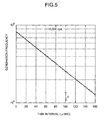
- the measured time intervals exhibit an exponential distribution, which causes a slight non-uniformity in the generation frequency of each random number value obtained in accordance with the measured time interval. While this level of non-uniformity has been ignored, it is desirable to eliminate such non-uniformity so as to produce a better random number.
- the present invention provides a random-number generating apparatus comprising a noise generating element, an amplifier for amplifying a waveform based on a noise generated in the noise generating element, a random-pulse generator for generating a random pulse when an output signal from the amplifier exceeds a given threshold from the state of being less than the threshold, or falls below the threshold from the state of being greater than the threshold, a reference-pulse generator for generating a reference pulse having a constant period, and a timer for measuring a time interval between the reference pulse and the random pulse.
- This random-number generating apparatus is operable to output the measured value in the timer as a random number value.
- the timer may include a clock-signal generator for generating a clock signal having a higher frequency than that of the reference pulse, and a counter for counting the number of clocks of the clock signal, wherein a counted value obtained by counting the number of clocks in the time interval between the reference pulse and the random pulse is used as the measured value.
- the present invention further provides a random-number generating apparatus comprising a noise generating element, an amplifier for amplifying a waveform based on a noise generated in the noise generating element, first random-pulse generator for generating a first random pulse when an output signal from the amplifier exceeds a given threshold from the state of being less than the threshold, second random-pulse generator for generating a second random pulse when an output signal from the amplifier falls below a given threshold from the state of being greater than the threshold, a reference-pulse generator for generating a reference pulse having a constant period, a clock-signal generator for generating a clock signal having a higher frequency than that of the reference pulse, first and second counters for counting the number of clocks in the clock signal, respectively, in opposite directions, and an operator for performing an exclusive-OR operation.
- the first counter is operable to count the number of clocks in a time interval between the reference pulse and the first random pulse
- the second counter is operable to count the number of clocks in a time interval between the reference pulse and the second random pulse.
- the operator is operable to perform the exclusive-OR operation for the respective counted values of the first counter and the second counter at each corresponding digit position, and output the operation result as a random number.
- the present invention may also be designed to provide two or more of the above random-number generating apparatuses, and lump the respective random numbers generated by these random-number generating apparatuses together as one random number, so as to increase a speed in generating random numbers.
- the noise generating element may be a thermal-noise generating element or a light-emitting element.
- the random number noise may be generated in accordance with a thermal noise when the thermal-noise generating element is used, or in accordance with a light-based noise when the light-emitting element is used.
- FIG. 1 is a block diagram showing a random-number generating circuit according to one embodiment of the present invention.
- the random-number generating circuit in FIG. 1 comprises two random-number generation sections indicated by the reference numerals 8a and 8b (the former will hereinafter be referred to as an "A-type random-number generation section” and the latter as a “B-type random-number generation section", respectively), and each of them is operable to generate random numbers in accordance with a single common thermal-noise generating element 10.
- each of these random-number generation sections and their circuit components is indicated, for example, simply as a "random-number generation section 8" by omitting the suffix a, b.
- the thermal-noise generating element 10 may be provided in each of the random-number generation sections.
- the thermal-noise generating element 10 is an element for outputting a pulsed potential variation based on thermal noises, and a resistor is typically used as the thermal-noise generating element in many cases. Generally, the generation of thermal noises is regarded as a random phenomenon. In the circuit of FIG. 1, no voltage is applied across the thermal-noise generating element 10 to eliminate a risk that an externally applied voltage will adversely affect the potential variation across the thermal-noise generating element to spoil the genuineness of a physical random number.
- Each of the reference numerals 12a, 12b indicates an amplifier for amplifying a thermal noise generated in the thermal-noise generating element 10, and each of the reference numerals 14a, 14b indicates a random pulse generator for generating a random pulse in accordance with the thermal noise.
- Each of the reference numerals 20a, 20b indicates a clock pulse generator for generating a clock pulse
- each of the reference numerals 16a, 16b indicates a counter for counting the clock pulse.
- Each of the reference numerals 18a, 18b indicates a reference pulse generator for triggering a counting operation in each of the counters 16a, 16b.
- the random-number generating circuit may have a single common clock pulse generator.
- FIG. 2(A) schematically shows the waveform of the microscopic potential variation based on thermal noises generated across the thermal-noise generating element 10.
- each of the thermal noises is random in terms of both temporal width and generation frequency.
- this potential variation is extremely minute, and thereby the waveform of the potential variation before the amplification cannot be observed in this form.
- the amplifier 12 is operable to amplify the thermal noises generated across the thermal-noise generating element 10. As described above, the thermal noises are a microscopic potential variation. Thus, in order to obtain a required amplification degree, the amplifier 12 may be composed of a multistage amplifier circuit, for example, comprising a preamplifier circuit and a main amplifier circuit.
- FIG. 2(B) schematically shows the waveform of the thermal noise amplified by the amplifier 12.
- An actual amplifier circuit has restrictions in a frequency characteristic and amplification degree, and thereby the thermal-noise-based waveform cannot be truly amplified. Specifically, in an output of the amplifier circuit, a high-speed potential variation having the higher frequency than an amplifiable frequency band or extremely minute potential variation will be cancelled. Further, the width of the thermal-noise-based pulse output from the amplifier circuit is affected by a time constant inherent in the amplifier circuit. Thus, the waveform illustrated in FIG. 2(B) is obtained under such influences of the characteristics of the amplifier circuit 12. As shown in FIG. 2(B), the duration of the obtained pulse is about 200 nanoseconds.
- the random pulse generator 14 is operable to extract a pulse having a constant temporal width (hereinafter referred to as a "random pulse") from the randomly generated thermal noises at the time when the output of the amplifier 12 exceeds a predetermined threshold.
- a predetermined threshold is set at a higher value, the number of random pulses to be obtained will be reduced, and a speed in generating a desired number of random numbers or a random-number generation speed will becomes lower, while an effect of eliminating influences by noises other than thermal noises or the like will be enhanced.
- this threshold is set at a lower value, the number of random pulses to be obtained will be increased, and the random-number generation speed will becomes higher, while noises adversely affecting the genuineness of a random number will be liable to be picked up.
- the threshold is determined by taking account of an actual application.
- the random pulse generator 14a is operable to generate a random pulse which rises at the time when the thermal-noise-based waveform exceeds a given threshold.
- the random pulse generator 14b is operable to generate a random pulse which rises at the time when the thermal-noise-based waveform falls below a given threshold from the state of being greater than the threshold.
- the respective thresholds in the random pulse generators 14a, 14b may be identical to one another, or may be different from one another.
- FIG. 2(C) schematically shows the waveform of the random pulse output from the random pulse generator 14a.
- Each of the random pulse generators 14a, 14b is configured to generate a random pulse having a pulse width of 10 nanoseconds as shown in FIG. 2(C). While the random pulse is based on thermal noises, it is finally obtained by subjecting the thermal-noise-based signal to a circuit-based processing. Thus, it is required to separately verify whether the generation frequency of the random pulse is actually random.
- each reference pulse generated from the reference pulse generators 18a, 18b serves as a trigger pulse for allowing a counting operation in each of the counters 16a, 16b to be initiated.
- each of the counters 16a, 16b is described on the assumption that it is a 4-bit counter.
- Each of the clock pulse generators 20a, 20b is configured to constantly generate a clock pulse having a substantially higher frequency than (e.g. about 300 times) the reference pulse to be generated by each of the reference pulse generators 18a, 18b.
- the counter 16a is a forward counter configured to increment one by one every time one clock pulse is entered therein.
- the counter 16b is a reverse counter configured to decrement one by one every time one clock pulse is entered therein.
- each of these counters is configured to be reset every time the counting operation for 4 bits (or for counting up to 16) is completed, and re-count from the beginning.
- One of the features of the random-number generating circuit is that the pair of reference pulse generators 18a, 18b and the forward and reverse counters 16a, 16b are provided as described above.
- each of the reference pulse generators 18a, 18b generates a reference pulse having a period equivalent to this average time interval of about 100 microseconds. While each of the counters 16a, 16b in this embodiment is described as a 4-bit counter, it is no more than one example, and may be any other suitable counter, such as an 8-bit counter or a 16-bit counter.
- FIG. 3 are explanatory diagrams of waveforms in the respective components of the A-type random-number generation section 8a illustrated in the upper portion of FIG. 1, or more particularly, explanatory diagrams of the relationship between reference pulses (A) generated from the reference pulse generator 18a, random pulses (B) generated from the random pulse generator 14a, clock pulses (C) generated from the clock pulse generator 20a, and counted values (D) counted by the counter 16a.
- reference pulses (A) generated from the reference pulse generator 18a random pulses (B) generated from the random pulse generator 14a
- clock pulses (C) generated from the clock pulse generator 20a
- counted values (D) counted by the counter 16a counted values counted by the counter 16a.
- random-number generation section 8b illustrated in the lower portion of FIG. 1, and thus explanation of the waveforms in random-number generation section 8b will be omitted herein.
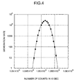
- FIG. 4 shows the result of a test using a random-number generating apparatus designed to generate about 100,000 thermal-noise-based pulses per second on an average, wherein the number of generated random numbers was counted for 10 seconds (or an average number of counted values was about 1,000,000), and this counting operation was successively repeated 135,000 times.
- Each of the test values is plotted on this figure as one black dot.
- the curve indicated by a solid line in FIG. 4 represents a Gaussian distribution having a deviation ⁇ of 1,025. It should be noted that the scale of the generation frequency on the vertical axis of FIG. 4 is a logarithmic value.
- a reference pulse is introduced. Then, a time interval between the reference pulse and a random pulse is measured, and the measured value is directly extracted as a random number.
- the random-number generating apparatus designed to subject respective values of the forward counter 16a and the reverse counter 16b at each corresponding digit position to an exclusive-OR operation, and use the result of the exclusive-OR operation as a final random number value can achieve the following effects.
- a speed in generating random numbers can be increased in proportion to the number.
- a high-speed random number to be obtained by this circuit can have further enhanced uniformity by connecting a plural number of the random-number generating circuits each originally having a uniformized generation frequency of each random number value, as indicated by the line (c) in FIG. 6.
- the integrity of physical random numbers can be advantageously maintained.
- the random-number generating apparatus in the above embodiment has been designed to use a reference pulse as a trigger pulse for allowing a counting operation in each of the counters 16a, 16b to be initiated, and stop the counting operation when a random pulse is entered in each of the counters, it may be designed in a reverse way or to use the random pulse as the trigger pulse for allowing a counting operation to be initiated, and stop the counting operation when the reference pulse is entered in each of the counters.
- each of the counted values of the counters 16a, 16b may be directly output as a final random number value.
- a physical random number is produced in accordance with thermal noises randomly generated by a thermal-noise generating element or light-based noises randomly generated by a light-emitting element.
- the physical random number can be generated in a simplified circuit configuration.
- the present invention can achieve a higher speed in generating random numbers and a uniformized generation frequency of each random number value.
- the present invention can be suitably applied to various simulations utilizing random numbers, such as derivatives, strength simulation for buildings, weather forecasting, or advanced game machines utilizing simulations.
Landscapes
- Engineering & Computer Science (AREA)
- Theoretical Computer Science (AREA)
- Physics & Mathematics (AREA)
- General Physics & Mathematics (AREA)
- General Engineering & Computer Science (AREA)
- Computational Mathematics (AREA)
- Mathematical Analysis (AREA)
- Mathematical Optimization (AREA)
- Pure & Applied Mathematics (AREA)
- Manipulation Of Pulses (AREA)
Abstract
Description
Claims (9)
- A random-number generating apparatus comprising:wherein the measured value in said timer is output as a random number value.a noise generating element;an amplifier for amplifying a waveform based on a noise generated in said noise generating element;a random-pulse generator for generating a random pulse when an output signal from said amplifier exceeds a given threshold from the state of being less than said threshold, or falls below said threshold from the state of being greater than said threshold;a reference-pulse generator for generating a reference pulse having a constant period; anda timer for measuring a time interval between said reference pulse and said random pulse,
- The random-number generating apparatus as defined in claim 1, wherein said timer includes a clock-signal generator for generating a clock signal having a higher frequency than that of said reference pulse, and a counter for counting the number of clocks of said clock signal,
wherein a counted value obtained by counting the number of clocks in the time interval between said reference pulse and said random pulse is used as said measured value. - A random-number generating apparatus comprising:wherein:a noise generating element;an amplifier for amplifying a waveform based on a noise generated in said noise generating element;first random-pulse generator for generating a first random pulse when an output signal from said amplifier exceeds a given threshold from the state of being less than said threshold;second random-pulse generator for generating a second random pulse when an output signal from said amplifier falls below a given threshold from the state of being greater than said threshold;a reference-pulse generator for generating a reference pulse having a constant period; anda clock-signal generator for generating a clock signal having a higher frequency than that of said reference pulse;first and second counters for counting the number of clocks in said clock signal, respectively, in opposite directions; andan operator for performing an exclusive-OR operation,said first counter is operable to count the number of clocks in a time interval between said reference pulse and said first random pulse;said second counter is operable to count the number of clocks in a time interval between said reference pulse and said second random pulse; andsaid operator is operable to perform the exclusive-OR operation for the respective counted values of said first counter and said second counter at each corresponding digit position, and output the operation result as a random number.
- A random-number generating apparatus comprising two or more of the random-number generating apparatuses as defined in either one of claims 1 to 3, and means for lumping the respective random numbers generated by said random-number generating apparatuses together as one random number, so as to increase a speed in generating random numbers.
- The random-number generating apparatus as defined in either one of claims 1 to 4,
wherein said noise generating element is a thermal-noise generating element, and said noise is a thermal noise. - The random-number generating apparatus as defined in either one of claims 1 to 4,
wherein said noise generating element is a light-emitting element, and said noise is a noise based on light. - A method for generating random numbers, comprising the steps of:generating a random pulse in accordance with the generation of a noise in a noise generating element;generating a reference pulse having a constant period; andmeasuring a time interval between said reference pulse and said random pulse, and outputting the measured value as a random number value.
- The method as defined in claim 7, wherein said noise generating element is a thermal-noise generating element, and said noise is a thermal noise.
- The method as defined in claim 7, wherein said noise generating element is a light-emitting element, and said noise is a noise based on light.
Applications Claiming Priority (3)
| Application Number | Priority Date | Filing Date | Title |
|---|---|---|---|
| JP2002236689 | 2002-08-14 | ||
| JP2002236689 | 2002-08-14 | ||
| PCT/JP2003/001100 WO2004017191A1 (en) | 2002-08-14 | 2003-02-04 | Random number generator and random number generation method |
Publications (3)
| Publication Number | Publication Date |
|---|---|
| EP1544726A1 true EP1544726A1 (en) | 2005-06-22 |
| EP1544726A4 EP1544726A4 (en) | 2007-10-03 |
| EP1544726B1 EP1544726B1 (en) | 2012-08-22 |
Family
ID=31884421
Family Applications (1)
| Application Number | Title | Priority Date | Filing Date |
|---|---|---|---|
| EP03788003A Expired - Lifetime EP1544726B1 (en) | 2002-08-14 | 2003-02-04 | Random number generator and random number generation method |
Country Status (5)
| Country | Link |
|---|---|
| US (1) | US8234322B2 (en) |
| EP (1) | EP1544726B1 (en) |
| JP (1) | JP4195007B2 (en) |
| AU (1) | AU2003285742A1 (en) |
| WO (1) | WO2004017191A1 (en) |
Cited By (5)
| Publication number | Priority date | Publication date | Assignee | Title |
|---|---|---|---|---|
| EP1821196A1 (en) | 2006-02-15 | 2007-08-22 | CryptoGraf Co., Ltd. | Method and apparatus for seeding a cryptographic random number generator |
| EP1755033A4 (en) * | 2004-05-24 | 2007-10-10 | Leisure Electronics Technology | Random number extraction method and random number generation device using the same |
| US8583712B2 (en) | 2007-09-18 | 2013-11-12 | Seagate Technology Llc | Multi-bit sampling of oscillator jitter for random number generation |
| US8768992B2 (en) | 2006-02-22 | 2014-07-01 | Qinetiq Limited | Apparatus and method for generating random numbers |
| WO2014200326A1 (en) * | 2013-06-11 | 2014-12-18 | Mimos Berhad | Device and method for outputting random data |
Families Citing this family (14)
| Publication number | Priority date | Publication date | Assignee | Title |
|---|---|---|---|---|
| TWI408903B (en) * | 2004-06-30 | 2013-09-11 | 露崎典平 | Random pulse generation source and semiconductor device, method and program for generating random number and/or probability using the source |
| JP4678335B2 (en) * | 2006-05-30 | 2011-04-27 | Fdk株式会社 | Physical random number generator |
| JP2009054075A (en) * | 2007-08-29 | 2009-03-12 | Osamu Kameda | System and method of generating random number |
| JP5295651B2 (en) * | 2008-06-13 | 2013-09-18 | 株式会社東芝 | Random number generator |
| JP5794741B2 (en) * | 2009-11-25 | 2015-10-14 | アクララ・テクノロジーズ・リミテッド・ライアビリティ・カンパニーAclara Technologies LLC. | Random number generator |
| US8762439B2 (en) * | 2011-04-14 | 2014-06-24 | Apple Inc. | System and method for random number generation using asynchronous boundaries and phase locked loops |
| US9477443B1 (en) | 2013-06-06 | 2016-10-25 | Tectrolabs L.L.C. | Method and apparatus of entropy source with multiple hardware random noise sources and continuous self-diagnostic logic |
| US10367645B2 (en) * | 2016-10-26 | 2019-07-30 | International Business Machines Corporation | Proof-of-work for smart contracts on a blockchain |
| KR102372740B1 (en) * | 2019-04-09 | 2022-03-14 | 한국전자통신연구원 | Random number generating device and operating method of the same |
| KR102792398B1 (en) * | 2019-06-17 | 2025-04-10 | 한국전자통신연구원 | Random number generating device and operating method of the same |
| US10901695B1 (en) * | 2020-03-03 | 2021-01-26 | Randaemon Sp. Z O.O. | Apparatus, systems, and methods for beta decay based true random number generator |
| US12055655B2 (en) * | 2021-06-24 | 2024-08-06 | Intel Corporation | Signal-to-noise ratio range consistency check for radar ghost target detection |
| CN114123977B (en) * | 2021-11-26 | 2022-11-29 | 南京鼓楼医院 | White noise generation method based on controllable fracture junction |
| CN117149136B (en) * | 2023-10-30 | 2024-03-29 | 华中师范大学 | Method and system for generating random telegraph noise |
Family Cites Families (17)
| Publication number | Priority date | Publication date | Assignee | Title |
|---|---|---|---|---|
| GB841287A (en) * | 1957-03-15 | 1960-07-13 | Her Majesty S Postmaster Cener | Improvements in or relating to random number indicating equipment |
| US3124753A (en) * | 1961-08-21 | 1964-03-10 | Methpuira | |
| US3612845A (en) * | 1968-07-05 | 1971-10-12 | Reed C Lawlor | Computer utilizing random pulse trains |
| JPS5178159A (en) * | 1974-12-28 | 1976-07-07 | Fuji Heavy Ind Ltd | |
| JPS51128239A (en) * | 1975-04-30 | 1976-11-09 | Nec Corp | Random-digital-pattern generating system |
| JPS5745645A (en) * | 1980-08-29 | 1982-03-15 | Matsushita Electric Ind Co Ltd | Random number generator |
| JPH11296348A (en) * | 1998-04-07 | 1999-10-29 | Takeshi Saito | Natural random number and hybrid random number generating device |
| JP2002533800A (en) * | 1998-12-18 | 2002-10-08 | ザ リージェンツ オブ ザ ユニバーシティ オブ カリフォルニア | Random number generator based on spontaneous alpha decay |
| JP2000276329A (en) * | 1999-03-26 | 2000-10-06 | Takeshi Saito | Device for generating very high speed physical random number |
| JP2000305753A (en) * | 1999-04-16 | 2000-11-02 | Takeshi Saito | Physical random number generating device |
| JP3480822B2 (en) * | 1999-11-02 | 2003-12-22 | 斎藤 威 | Thermal noise random pulse generator and random number generator |
| US6763363B1 (en) * | 1999-12-02 | 2004-07-13 | Honeywell International Inc. | Computer efficient linear feedback shift register |
| JP4521708B2 (en) * | 2001-03-12 | 2010-08-11 | ルネサスエレクトロニクス株式会社 | Random number generator |
| JP4467216B2 (en) * | 2001-09-07 | 2010-05-26 | Necエレクトロニクス株式会社 | Random number generation method and apparatus |
| US6963888B2 (en) * | 2001-11-29 | 2005-11-08 | Koninklijke Philips Electronics N.V. | Method and apparatus for preventing noise from influencing a random number generator based on flip-flop meta-stability |
| AU2003261169A1 (en) * | 2002-07-16 | 2004-02-02 | Ruth, Michael | A system and method for providing corporate governance-related services |
| US20040107124A1 (en) * | 2003-09-24 | 2004-06-03 | James Sharpe | Software Method for Regulatory Compliance |
-
2003
- 2003-02-04 EP EP03788003A patent/EP1544726B1/en not_active Expired - Lifetime
- 2003-02-04 JP JP2004528826A patent/JP4195007B2/en not_active Expired - Lifetime
- 2003-02-04 WO PCT/JP2003/001100 patent/WO2004017191A1/en not_active Ceased
- 2003-02-04 AU AU2003285742A patent/AU2003285742A1/en not_active Abandoned
-
2005
- 2005-02-14 US US11/058,725 patent/US8234322B2/en not_active Expired - Fee Related
Cited By (6)
| Publication number | Priority date | Publication date | Assignee | Title |
|---|---|---|---|---|
| EP1755033A4 (en) * | 2004-05-24 | 2007-10-10 | Leisure Electronics Technology | Random number extraction method and random number generation device using the same |
| US8037117B2 (en) | 2004-05-24 | 2011-10-11 | Leisure Electronics Technology Co., Ltd. | Random number derivation method and random number generator using same |
| EP1821196A1 (en) | 2006-02-15 | 2007-08-22 | CryptoGraf Co., Ltd. | Method and apparatus for seeding a cryptographic random number generator |
| US8768992B2 (en) | 2006-02-22 | 2014-07-01 | Qinetiq Limited | Apparatus and method for generating random numbers |
| US8583712B2 (en) | 2007-09-18 | 2013-11-12 | Seagate Technology Llc | Multi-bit sampling of oscillator jitter for random number generation |
| WO2014200326A1 (en) * | 2013-06-11 | 2014-12-18 | Mimos Berhad | Device and method for outputting random data |
Also Published As
| Publication number | Publication date |
|---|---|
| EP1544726A4 (en) | 2007-10-03 |
| JPWO2004017191A1 (en) | 2005-12-08 |
| WO2004017191A1 (en) | 2004-02-26 |
| AU2003285742A8 (en) | 2004-03-03 |
| US8234322B2 (en) | 2012-07-31 |
| AU2003285742A1 (en) | 2004-03-03 |
| EP1544726B1 (en) | 2012-08-22 |
| JP4195007B2 (en) | 2008-12-10 |
| US20050198091A1 (en) | 2005-09-08 |
Similar Documents
| Publication | Publication Date | Title |
|---|---|---|
| EP1544726B1 (en) | Random number generator and random number generation method | |
| US7080106B2 (en) | Random number generating method and random number generating device | |
| JP3480822B2 (en) | Thermal noise random pulse generator and random number generator | |
| EP1755033A1 (en) | Random number extraction method and random number generation device using the same | |
| US7266575B2 (en) | Random number generator which can generate a random number based on an uniform distribution | |
| US20100332575A1 (en) | High-Speed Random Number Generator | |
| JP2003234788A (en) | Apparatus for measuring characteristic of binary pulse bit stream, and characteristic determining method | |
| US9836280B2 (en) | Arrangement and method for checking the entropy of a random number sequence | |
| CN103235863B (en) | Signal source system of analog energy spectrum | |
| JPH11160432A (en) | Optical pulse radar and optical pulse receiver | |
| US8638930B2 (en) | Random number verification method and random number verification apparatus | |
| JPH06237231A (en) | Waveform discriminating device | |
| CN116388959B (en) | Ability testing method and system for fault attack based on Hamming weight | |
| US3456208A (en) | Random noise generator having gaussian amplitude probability distribution | |
| RU2251704C2 (en) | Method of detection of periodic pulse sequences and estimation of period sequences | |
| JP4837549B2 (en) | Physical random number generator and physical random number generator | |
| JP2003196081A (en) | Rapid test method for true random number generation chip | |
| US6931057B2 (en) | Method, article of manufacture and system to determine a bit rate of a signal | |
| JP2704635B2 (en) | Delay time measuring device | |
| SU857960A1 (en) | Random number generator | |
| JP2003014786A (en) | Trigger signal generator | |
| SU942011A1 (en) | Random number pickup | |
| JP2001075782A (en) | Semiconductor physical random-number generating device | |
| MAHMOOD et al. | Noise generator with programmable distribution | |
| JPS59178033A (en) | Detecting system of leading characteristic of repeater |
Legal Events
| Date | Code | Title | Description |
|---|---|---|---|
| PUAI | Public reference made under article 153(3) epc to a published international application that has entered the european phase |
Free format text: ORIGINAL CODE: 0009012 |
|
| 17P | Request for examination filed |
Effective date: 20050214 |
|
| AK | Designated contracting states |
Kind code of ref document: A1 Designated state(s): AT BE BG CH CY CZ DE DK EE ES FI FR GB GR HU IE IT LI LU MC NL PT SE SI SK TR |
|
| AX | Request for extension of the european patent |
Extension state: RO |
|
| A4 | Supplementary search report drawn up and despatched |
Effective date: 20070905 |
|
| 17Q | First examination report despatched |
Effective date: 20090218 |
|
| GRAP | Despatch of communication of intention to grant a patent |
Free format text: ORIGINAL CODE: EPIDOSNIGR1 |
|
| GRAS | Grant fee paid |
Free format text: ORIGINAL CODE: EPIDOSNIGR3 |
|
| GRAA | (expected) grant |
Free format text: ORIGINAL CODE: 0009210 |
|
| AK | Designated contracting states |
Kind code of ref document: B1 Designated state(s): AT BE BG CH CY CZ DE DK EE ES FI FR GB GR HU IE IT LI LU MC NL PT SE SI SK TR |
|
| AX | Request for extension of the european patent |
Extension state: RO |
|
| REG | Reference to a national code |
Ref country code: GB Ref legal event code: FG4D |
|
| REG | Reference to a national code |
Ref country code: CH Ref legal event code: EP |
|
| REG | Reference to a national code |
Ref country code: IE Ref legal event code: FG4D |
|
| REG | Reference to a national code |
Ref country code: AT Ref legal event code: REF Ref document number: 572283 Country of ref document: AT Kind code of ref document: T Effective date: 20120915 |
|
| REG | Reference to a national code |
Ref country code: DE Ref legal event code: R096 Ref document number: 60341905 Country of ref document: DE Effective date: 20121018 |
|
| REG | Reference to a national code |
Ref country code: NL Ref legal event code: VDEP Effective date: 20120822 |
|
| REG | Reference to a national code |
Ref country code: AT Ref legal event code: MK05 Ref document number: 572283 Country of ref document: AT Kind code of ref document: T Effective date: 20120822 |
|
| PG25 | Lapsed in a contracting state [announced via postgrant information from national office to epo] |
Ref country code: CY Free format text: LAPSE BECAUSE OF FAILURE TO SUBMIT A TRANSLATION OF THE DESCRIPTION OR TO PAY THE FEE WITHIN THE PRESCRIBED TIME-LIMIT Effective date: 20120822 Ref country code: AT Free format text: LAPSE BECAUSE OF FAILURE TO SUBMIT A TRANSLATION OF THE DESCRIPTION OR TO PAY THE FEE WITHIN THE PRESCRIBED TIME-LIMIT Effective date: 20120822 Ref country code: FI Free format text: LAPSE BECAUSE OF FAILURE TO SUBMIT A TRANSLATION OF THE DESCRIPTION OR TO PAY THE FEE WITHIN THE PRESCRIBED TIME-LIMIT Effective date: 20120822 |
|
| PG25 | Lapsed in a contracting state [announced via postgrant information from national office to epo] |
Ref country code: GR Free format text: LAPSE BECAUSE OF FAILURE TO SUBMIT A TRANSLATION OF THE DESCRIPTION OR TO PAY THE FEE WITHIN THE PRESCRIBED TIME-LIMIT Effective date: 20121123 Ref country code: BE Free format text: LAPSE BECAUSE OF FAILURE TO SUBMIT A TRANSLATION OF THE DESCRIPTION OR TO PAY THE FEE WITHIN THE PRESCRIBED TIME-LIMIT Effective date: 20120822 Ref country code: SE Free format text: LAPSE BECAUSE OF FAILURE TO SUBMIT A TRANSLATION OF THE DESCRIPTION OR TO PAY THE FEE WITHIN THE PRESCRIBED TIME-LIMIT Effective date: 20120822 Ref country code: PT Free format text: LAPSE BECAUSE OF FAILURE TO SUBMIT A TRANSLATION OF THE DESCRIPTION OR TO PAY THE FEE WITHIN THE PRESCRIBED TIME-LIMIT Effective date: 20121224 Ref country code: SI Free format text: LAPSE BECAUSE OF FAILURE TO SUBMIT A TRANSLATION OF THE DESCRIPTION OR TO PAY THE FEE WITHIN THE PRESCRIBED TIME-LIMIT Effective date: 20120822 |
|
| PG25 | Lapsed in a contracting state [announced via postgrant information from national office to epo] |
Ref country code: NL Free format text: LAPSE BECAUSE OF FAILURE TO SUBMIT A TRANSLATION OF THE DESCRIPTION OR TO PAY THE FEE WITHIN THE PRESCRIBED TIME-LIMIT Effective date: 20120822 |
|
| PG25 | Lapsed in a contracting state [announced via postgrant information from national office to epo] |
Ref country code: ES Free format text: LAPSE BECAUSE OF FAILURE TO SUBMIT A TRANSLATION OF THE DESCRIPTION OR TO PAY THE FEE WITHIN THE PRESCRIBED TIME-LIMIT Effective date: 20121203 Ref country code: EE Free format text: LAPSE BECAUSE OF FAILURE TO SUBMIT A TRANSLATION OF THE DESCRIPTION OR TO PAY THE FEE WITHIN THE PRESCRIBED TIME-LIMIT Effective date: 20120822 Ref country code: DK Free format text: LAPSE BECAUSE OF FAILURE TO SUBMIT A TRANSLATION OF THE DESCRIPTION OR TO PAY THE FEE WITHIN THE PRESCRIBED TIME-LIMIT Effective date: 20120822 Ref country code: CZ Free format text: LAPSE BECAUSE OF FAILURE TO SUBMIT A TRANSLATION OF THE DESCRIPTION OR TO PAY THE FEE WITHIN THE PRESCRIBED TIME-LIMIT Effective date: 20120822 |
|
| PG25 | Lapsed in a contracting state [announced via postgrant information from national office to epo] |
Ref country code: IT Free format text: LAPSE BECAUSE OF FAILURE TO SUBMIT A TRANSLATION OF THE DESCRIPTION OR TO PAY THE FEE WITHIN THE PRESCRIBED TIME-LIMIT Effective date: 20120822 Ref country code: SK Free format text: LAPSE BECAUSE OF FAILURE TO SUBMIT A TRANSLATION OF THE DESCRIPTION OR TO PAY THE FEE WITHIN THE PRESCRIBED TIME-LIMIT Effective date: 20120822 |
|
| PLBE | No opposition filed within time limit |
Free format text: ORIGINAL CODE: 0009261 |
|
| STAA | Information on the status of an ep patent application or granted ep patent |
Free format text: STATUS: NO OPPOSITION FILED WITHIN TIME LIMIT |
|
| 26N | No opposition filed |
Effective date: 20130523 |
|
| PG25 | Lapsed in a contracting state [announced via postgrant information from national office to epo] |
Ref country code: BG Free format text: LAPSE BECAUSE OF FAILURE TO SUBMIT A TRANSLATION OF THE DESCRIPTION OR TO PAY THE FEE WITHIN THE PRESCRIBED TIME-LIMIT Effective date: 20121122 |
|
| REG | Reference to a national code |
Ref country code: DE Ref legal event code: R097 Ref document number: 60341905 Country of ref document: DE Effective date: 20130523 |
|
| PG25 | Lapsed in a contracting state [announced via postgrant information from national office to epo] |
Ref country code: MC Free format text: LAPSE BECAUSE OF NON-PAYMENT OF DUE FEES Effective date: 20130228 |
|
| REG | Reference to a national code |
Ref country code: CH Ref legal event code: PL |
|
| PG25 | Lapsed in a contracting state [announced via postgrant information from national office to epo] |
Ref country code: LI Free format text: LAPSE BECAUSE OF NON-PAYMENT OF DUE FEES Effective date: 20130228 Ref country code: CH Free format text: LAPSE BECAUSE OF NON-PAYMENT OF DUE FEES Effective date: 20130228 |
|
| REG | Reference to a national code |
Ref country code: IE Ref legal event code: MM4A |
|
| PG25 | Lapsed in a contracting state [announced via postgrant information from national office to epo] |
Ref country code: IE Free format text: LAPSE BECAUSE OF NON-PAYMENT OF DUE FEES Effective date: 20130204 |
|
| PGFP | Annual fee paid to national office [announced via postgrant information from national office to epo] |
Ref country code: GB Payment date: 20141223 Year of fee payment: 13 |
|
| PGFP | Annual fee paid to national office [announced via postgrant information from national office to epo] |
Ref country code: FR Payment date: 20141223 Year of fee payment: 13 |
|
| PG25 | Lapsed in a contracting state [announced via postgrant information from national office to epo] |
Ref country code: TR Free format text: LAPSE BECAUSE OF FAILURE TO SUBMIT A TRANSLATION OF THE DESCRIPTION OR TO PAY THE FEE WITHIN THE PRESCRIBED TIME-LIMIT Effective date: 20120822 |
|
| PG25 | Lapsed in a contracting state [announced via postgrant information from national office to epo] |
Ref country code: LU Free format text: LAPSE BECAUSE OF NON-PAYMENT OF DUE FEES Effective date: 20130204 Ref country code: HU Free format text: LAPSE BECAUSE OF FAILURE TO SUBMIT A TRANSLATION OF THE DESCRIPTION OR TO PAY THE FEE WITHIN THE PRESCRIBED TIME-LIMIT; INVALID AB INITIO Effective date: 20030204 |
|
| PGFP | Annual fee paid to national office [announced via postgrant information from national office to epo] |
Ref country code: DE Payment date: 20150330 Year of fee payment: 13 |
|
| REG | Reference to a national code |
Ref country code: DE Ref legal event code: R119 Ref document number: 60341905 Country of ref document: DE |
|
| GBPC | Gb: european patent ceased through non-payment of renewal fee |
Effective date: 20160204 |
|
| REG | Reference to a national code |
Ref country code: FR Ref legal event code: ST Effective date: 20161028 |
|
| PG25 | Lapsed in a contracting state [announced via postgrant information from national office to epo] |
Ref country code: GB Free format text: LAPSE BECAUSE OF NON-PAYMENT OF DUE FEES Effective date: 20160204 Ref country code: FR Free format text: LAPSE BECAUSE OF NON-PAYMENT OF DUE FEES Effective date: 20160229 Ref country code: DE Free format text: LAPSE BECAUSE OF NON-PAYMENT OF DUE FEES Effective date: 20160901 |