EP1544674B1 - Méthode de traitement d'un support d'image radiographique - Google Patents
Méthode de traitement d'un support d'image radiographique Download PDFInfo
- Publication number
- EP1544674B1 EP1544674B1 EP03104749A EP03104749A EP1544674B1 EP 1544674 B1 EP1544674 B1 EP 1544674B1 EP 03104749 A EP03104749 A EP 03104749A EP 03104749 A EP03104749 A EP 03104749A EP 1544674 B1 EP1544674 B1 EP 1544674B1
- Authority
- EP
- European Patent Office
- Prior art keywords
- data
- image carrier
- read
- image
- calibration data
- Prior art date
- Legal status (The legal status is an assumption and is not a legal conclusion. Google has not performed a legal analysis and makes no representation as to the accuracy of the status listed.)
- Expired - Lifetime
Links
- 238000012545 processing Methods 0.000 title claims abstract description 61
- 238000003860 storage Methods 0.000 title claims description 41
- 238000000034 method Methods 0.000 title claims description 26
- 230000005855 radiation Effects 0.000 title claims description 9
- 230000035945 sensitivity Effects 0.000 claims abstract description 36
- OAICVXFJPJFONN-UHFFFAOYSA-N Phosphorus Chemical compound [P] OAICVXFJPJFONN-UHFFFAOYSA-N 0.000 claims description 31
- NUHSROFQTUXZQQ-UHFFFAOYSA-N isopentenyl diphosphate Chemical compound CC(=C)CCO[P@](O)(=O)OP(O)(O)=O NUHSROFQTUXZQQ-UHFFFAOYSA-N 0.000 description 28
- 230000003287 optical effect Effects 0.000 description 15
- 230000005540 biological transmission Effects 0.000 description 10
- 238000007781 pre-processing Methods 0.000 description 7
- 238000012217 deletion Methods 0.000 description 6
- 230000037430 deletion Effects 0.000 description 6
- 239000003550 marker Substances 0.000 description 5
- 230000008569 process Effects 0.000 description 5
- 239000000969 carrier Substances 0.000 description 4
- 230000000638 stimulation Effects 0.000 description 4
- 238000012937 correction Methods 0.000 description 3
- 230000007547 defect Effects 0.000 description 3
- 230000002950 deficient Effects 0.000 description 3
- 230000008901 benefit Effects 0.000 description 2
- LYQFWZFBNBDLEO-UHFFFAOYSA-M caesium bromide Chemical compound [Br-].[Cs+] LYQFWZFBNBDLEO-UHFFFAOYSA-M 0.000 description 2
- 230000006870 function Effects 0.000 description 2
- 238000004519 manufacturing process Methods 0.000 description 2
- 230000007246 mechanism Effects 0.000 description 2
- 230000004048 modification Effects 0.000 description 2
- 238000012986 modification Methods 0.000 description 2
- 238000002601 radiography Methods 0.000 description 2
- 238000005452 bending Methods 0.000 description 1
- 238000007906 compression Methods 0.000 description 1
- 238000013144 data compression Methods 0.000 description 1
- 230000006735 deficit Effects 0.000 description 1
- 230000001419 dependent effect Effects 0.000 description 1
- 238000011156 evaluation Methods 0.000 description 1
- 230000036541 health Effects 0.000 description 1
- 230000006386 memory function Effects 0.000 description 1
- 238000010791 quenching Methods 0.000 description 1
- 230000000171 quenching effect Effects 0.000 description 1
- 239000007787 solid Substances 0.000 description 1
- 238000001228 spectrum Methods 0.000 description 1
- 230000007723 transport mechanism Effects 0.000 description 1
Images

Classifications
-
- G—PHYSICS
- G03—PHOTOGRAPHY; CINEMATOGRAPHY; ANALOGOUS TECHNIQUES USING WAVES OTHER THAN OPTICAL WAVES; ELECTROGRAPHY; HOLOGRAPHY
- G03B—APPARATUS OR ARRANGEMENTS FOR TAKING PHOTOGRAPHS OR FOR PROJECTING OR VIEWING THEM; APPARATUS OR ARRANGEMENTS EMPLOYING ANALOGOUS TECHNIQUES USING WAVES OTHER THAN OPTICAL WAVES; ACCESSORIES THEREFOR
- G03B42/00—Obtaining records using waves other than optical waves; Visualisation of such records by using optical means
- G03B42/02—Obtaining records using waves other than optical waves; Visualisation of such records by using optical means using X-rays
- G03B42/04—Holders for X-ray films
-
- A—HUMAN NECESSITIES
- A61—MEDICAL OR VETERINARY SCIENCE; HYGIENE
- A61B—DIAGNOSIS; SURGERY; IDENTIFICATION
- A61B6/00—Apparatus or devices for radiation diagnosis; Apparatus or devices for radiation diagnosis combined with radiation therapy equipment
- A61B6/44—Constructional features of apparatus for radiation diagnosis
- A61B6/4494—Means for identifying the diagnostic device
-
- G—PHYSICS
- G01—MEASURING; TESTING
- G01T—MEASUREMENT OF NUCLEAR OR X-RADIATION
- G01T1/00—Measuring X-radiation, gamma radiation, corpuscular radiation, or cosmic radiation
- G01T1/16—Measuring radiation intensity
- G01T1/20—Measuring radiation intensity with scintillation detectors
- G01T1/2012—Measuring radiation intensity with scintillation detectors using stimulable phosphors, e.g. stimulable phosphor sheets
Definitions
- the sensitivity of the respective X-ray storage phosphor layer must be taken into account, inter alia, during processing of the image signals obtained when the image carrier is read out.
- the corresponding data which represent a measure of the sensitivity of the storage phosphor layer of an image carrier for X-radiation, are supplied in the prior art usually ex works on a separate disk with the image carrier. In the case of confusion of the individual data carriers, which generally belong to different image carriers, it may happen that the image signals obtained from a storage phosphor layer of an image carrier are erroneously corrected with the corresponding data of another image carrier. This leads to an intolerable falsification of the read X-ray information.
- the inventive method for processing the image carrier is characterized in that the image carrier comprises an electronic memory for storing calibration data of the image carrier, which represent a measure of the sensitivity of the image carrier for X-radiation and in a processing of image signals, which in a readout of the X-ray information
- the calibration data can be stored after a first reading of the calibration data from the electronic memory of the image carrier in a memory, in particular in a central memory or in a memory of a read-out device.
- the calibration data of this image carrier stored after the first read out are then read from the memory, in particular the memory of the read device or the central memory.
- the calibration data are available for the image signal processing in a shorter time than when the two-dimensional data record is read again from the electronic memory of the image carrier. Also possible transmission errors when reading the record from the electronic memory can be avoided.
- the first readout of the calibration data of the image carrier preferably takes place from the electronic memory of the image carrier in the read-out device.
- the electronic memory is preferably designed as an integrated electronic circuit with a non-volatile memory, for example as ROM, PROM, EPROM or EEPROM.
- a non-volatile memory for example as ROM, PROM, EPROM or EEPROM.
- the calibration data of the image carrier is a measure of a storage phosphor layer of the image carrier locally variable sensitivity of the image carrier for X-ray. Not only different sensitivities of individual image carriers are considered, but also individually occurring variations in sensitivity over the entire surface of the storage phosphor Layer of a single image carrier. The accuracy of the calibration is thereby increased.
- the calibration data which represent a measure of the locally variable sensitivity of the image carrier for X-radiation, are preferably stored in a two-dimensional data field in the electronic memory of the image carrier.
- the calibration data of the image carrier reproduce the locally variable sensitivity of the image carrier in individual regions of the image carrier, wherein the individual regions correspond to the individual pixels that are obtained when reading out the X-ray information stored in the image carrier. This allows a pixel-accurate calibration, which takes into account locally different sensitivities with very high accuracy.
- the calibration data of the image carrier reproduce the locally variable sensitivity of the image carrier in individual regions of the image carrier, wherein the individual regions are larger than the individual pixels that are stored in a readout of the images stored in the image carrier X-ray information can be obtained.
- the memory requirements for the calibration data in the electronic memory can be greatly reduced, while at the same time locally different sensitivities are taken into account with a high degree of accuracy.
- the calibration data of the image carrier are stored in a calibration data group in the electronic memory of the image carrier.
- the image carrier comprises an image plate for storing the X-ray information, wherein the electronic memory is preferably attached to the image plate. This ensures a secure assignment of the calibration data stored in the electronic memory to the associated image plate.
- the image plate comprises a carrier layer with a storage phosphor layer located on the front side of the carrier layer and the electronic memory is located in an edge region of the carrier layer, in particular outside the storage phosphor layer, and / or on the front side Rear side of the carrier layer is attached.
- the electronic memory is located in an edge region of the carrier layer, in particular outside the storage phosphor layer, and / or on the front side Rear side of the carrier layer is attached.
- the image carrier next to the image plate comprises a cassette which can receive the image plate while shielding from ambient light. If the electronic memory is designed for contactless data transmission, this can be Memory contents are also read with a corresponding RF reader from the outside of the cassette through the cassette wall.
- the calibration data are stored in the electronic memory of the image carrier in compressed form.
- the storage space requirement can be greatly reduced.
- JPEG is suitable.
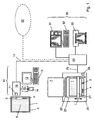
- the image carrier for X-ray information consists of a cassette 2 with an image plate 1 located therein.
- the image plate 1 comprises a carrier layer with a storage phosphor layer 5 applied thereon.
- the storage phosphor layer 5 preferably has a storage phosphor based on BaFBr: Eu or CsBr: Eu up.
- the integrated circuit 3 may be attached to the cassette 2.
- the data transmission between the integrated circuit 3 and the ID station 10 is preferably contactless. In this way, an exact positioning of the image plate 1 and the circuit 3 relative to the ID station 10, as would be required in a contact-type data transmission omitted.
- the contactless data transmission is preferably carried out by means of radio frequency waves (RF waves).
- the ID station 10 has a corresponding first read-write device 11 with an RF transmitter and an RF receiver.
- the integrated circuit 3 is preferably in the form of a so-called RF label, which is also referred to as RF tag, attached to the image plate 1, for example, glued.
- RF tag comprises, in addition to the integrated circuit 3, an antenna designed as a transponder coil.
- the integrated circuit 3 may also be attached to the image plate 1 in the form of a chip card in which an RF tag is inserted into a card-shaped plastic body.
- the smart card is preferably releasably attached to the image panel 1, e.g. by means of a simple plug connection in the edge region of the image plate 1.
- a locking mechanism may be provided, e.g.
- the ID station 10 includes one or more input devices for inputting data which are specific or required, for example, for a patient to be examined, the read-out of the image plate 1 or the further processing of image data read from the image plate 1.
- the input devices include a keyboard 13 with display unit 12, such.
- a card reader 15 for a card 14 on which there are data to be entered.
- the card 14 is a chip card, for example a health insurance card, on which patient-specific data, such as name, address, date of birth and insurance number of a patient are stored.
- the card reader 15 reads out these data from the card 14 and transfers them to a buffer 16 of the ID station 10.
- the data entered via the keyboard 13 are also transferred to the buffer 16.
- the display unit 12 can preferably also be a so-called touchscreen, in which displayed functions and / or data can be selected by touching the corresponding areas of the display.
- the input data is transferred to the first read-write device 11 and written in the memory of the integrated circuit 3 on the optical disk 1.
- the scanner 21 is preferably designed as a so-called line scanner, which has a line-shaped stimulation light source, preferably with laser diodes arranged in a row, and a line-shaped detector, preferably a linear CCD array.
- a line-shaped stimulation light source preferably with laser diodes arranged in a row
- a line-shaped detector preferably a linear CCD array.
- emission light is excited whose intensity corresponds to the X-ray information stored in the storage phosphor layer 5.
- the emission light is detected by the line-shaped detector and converted into corresponding image signals.
- the storage phosphor layer 5 is successively read line by line, a two-dimensional image of the stored X-ray information being obtained.
- the scanner 21 may also be designed as a so-called flying spot scanner, in which a single laser beam is directed onto the storage phosphor layer 5 by a rotating polygon mirror, as a result of which it is scanned point by point along individual lines.
- the read-out device 20 comprises a second read-write device 24 with which data can be read from or written into the integrated circuit 3.
- the second read-write device 24 is also preferably designed for contactless data transmission, in particular by means of RF waves.
- the data read out from the memory of the integrated circuit 3 with the second read-write device 24 are used in particular for controlling the readout of the image plate 1 with the scanner 21 and / or for controlling the deletion of the image plate 1 with the deletion device 23.
- data may be written into the integrated circuit 3 by the second read / write device 24 to preferably update data on the processing status of the optical disk 1, for example, whether the optical disk 1 has already been read out or erased.
- the image data stored in the central memory 40 can then be further processed and / or reproduced in the playback device 30.
- the reproduction device 30 comprises a monitor 31 which can be controlled by means of a keyboard 32a.
- a hardcopy device 33 for example a laser printer, may also be provided for outputting the image data.
- the central memory 40 can optionally be connected to a network 50, in particular to a local area network (LAN). This makes it possible for other systems, in particular other ID stations and / or playback devices, to be able to access the data or image data stored in the central memory 40.
- LAN local area network
- the central memory 40 may be formed as a separate central unit which may be e.g. can be integrated in a central file server. Alternatively, however, the central memory 40 may also be an integral part of the ID station 10, the read-out device 20 or the playback device 30.
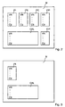
- the version number VN at the beginning of each data group indicates in which data structure the data of a data group is stored. This opens up the possibility of providing different data structures of one and the same data group. This is always necessary if other or additional data is to be stored in the memory M, for example in the case of a new type of image plate or a new type of processing of the image data.
- the individual components of the system e.g. the ID station 10, the read-out device 20 and the playback device 30, respectively, recognize which data is contained in the respective data group and in which data length, sequence etc. this data is present.
- the check sum CS at the end of each data group is derived from the individual data in this data group. Based on the respective checksum CS can be determined whether the data of this data group have been stored or read without error.
- the content of the image carrier data group IPI is additionally provided as a visually readable marker 4 (see FIG Fig. 1 ) is applied to the image plate 1 and / or the cassette 2.
- a visually readable marker 4 see FIG Fig. 1
- a mark 4 may be for example as follows: 301 - 6 ⁇ KBQMF ⁇ 0001 - 20030702 - 1 - 1 - 0 - 1000 - 1000 - 123
- the data taken from the marker 4 can easily be written to the memory of the new integrated circuit at the ID station 10 without requiring a new initialization from the manufacturer of the image plate 1 or cassette 2.
- the data of the marker 4 are read by an operator, entered via the keyboard 13 of the ID station 10 and then written into the memory of the new integrated circuit.
- readable mark 4 represents a particularly simple possibility for additional protection of data stored in the integrated circuit 3.
- a machine-readable mark (not shown) may be provided, for example in the form of a Barcodes or magnetic stripe. To enter the data contained in the machine-readable mark then a corresponding bar code or magnetic stripe reader is required, which forwards the machine-read data to the ID station 10, where they can then be written in the new integrated circuit.
- the patient data group IDP can also be dispensed with if reference codes for patient data are already provided in the processing data group IPP, as described above.
- the appropriate patient data such as Name and / or date of birth and / or sex of the patient, refer to the central memory 40.
- image plates 1 is the mark 4, which represents part of the data stored in the memory M of the integrated circuit 3, in particular data of the image carrier data group IPI, mounted on the back of the carrier layer of the image plate 1.
- the mark 4 is therefore shown in dashed lines.
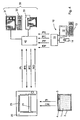
- Fig. 5 shows a second example of a structure of the data stored in the integrated circuit 3 of the image carrier in the in Fig. 4 illustrated variant of the data flow.
- data of the image carrier and calibration data group IPI or CAL are stored in the memory M.
- IPI and CAL apply the above remarks Fig. 2 corresponding.
Landscapes
- Health & Medical Sciences (AREA)
- Life Sciences & Earth Sciences (AREA)
- Physics & Mathematics (AREA)
- Medical Informatics (AREA)
- General Physics & Mathematics (AREA)
- High Energy & Nuclear Physics (AREA)
- Molecular Biology (AREA)
- Engineering & Computer Science (AREA)
- Pathology (AREA)
- Heart & Thoracic Surgery (AREA)
- Nuclear Medicine, Radiotherapy & Molecular Imaging (AREA)
- Optics & Photonics (AREA)
- Spectroscopy & Molecular Physics (AREA)
- Radiology & Medical Imaging (AREA)
- Biomedical Technology (AREA)
- Biophysics (AREA)
- Surgery (AREA)
- Animal Behavior & Ethology (AREA)
- General Health & Medical Sciences (AREA)
- Public Health (AREA)
- Veterinary Medicine (AREA)
- Apparatus For Radiation Diagnosis (AREA)
- Image Analysis (AREA)
- Radiography Using Non-Light Waves (AREA)
Claims (11)
- Procédé de traitement d'un support d'image (1, 2) pour l'enregistrement de radiographies,- dans lequel le support d'image (1, 2) comprend une mémoire électronique (M) pour la mémorisation de données de calibrage du support d'image (1, 2) qui représentent une mesure de la sensibilité du support d'image (1, 2) pour des rayons X et qui peuvent être exploitées lors d'un traitement de signaux vidéo qui sont obtenus lors d'une lecture de l'information radiographique sur le support d'image (1, 2) dans un dispositif de lecture (20),- dans lequel les données de calibrage après une première lecture des données de calibrage dans la mémoire électronique (M) du support d'image (1, 2) sont mémorisées, notamment au moyen d'un poste d'identification ID ou du dispositif de lecture (20), dans une mémoire centrale (40) ou dans une mémoire du dispositif de lecture (20),- dans lequel les données de calibrage sont exploitées lors du traitement du support d'image (1, 2) dans le dispositif de lecture (20), et- dans lequel, lors d'un nouveau traitement du même support d'image (1, 2) dans le dispositif de lecture (20), les données de calibrage de ce support de données (1, 2) qui ont été mémorisées dans la mémoire centrale (40) ou dans la mémoire du dispositif de lecture (20) après la première lecture des données de calibrage dans la mémoire électronique (M) du support d'image (1, 2) sont lues dans la mémoire centrale (40) ou dans la mémoire du dispositif de lecture (20).
- Procédé selon la revendication 1, caractérisé par le fait que la première lecture des données de calibrage du support d'image (1, 2) dans la mémoire électronique (M) du support d'image (1, 2) s'effectue dans le dispositif de lecture (20).
- Procédé selon la revendication 1 ou 2, caractérisé par le fait que les données de calibrage du support d'image (1, 2) représentent une mesure de la sensibilité du support d'image (1, 2) pour des rayons X, laquelle sensibilité est localement variable sur une couche luminescente de mémorisation (5) du support d'image (1, 2).
- Procédé selon la revendication 3, caractérisé par le fait que les données de calibrage du support d'image (1, 2) sont mémorisées dans un champ de données bidimensionnel dans la mémoire électronique (M) du support d'image (1, 2).
- Procédé selon la revendication 3 ou 4, caractérisé par le fait que les données de calibrage du support d'image (1, 2) reproduisent la sensibilité localement variable du support d'image (1, 2) dans différentes zones du support d'image (1, 2), les zones individuelles correspondant à des points d'image individuels qui sont obtenus lors d'une lecture de l'information radiographique mémorisée dans le support d'image (1, 2).
- Procédé selon la revendication 3 ou 4, caractérisé par le fait que les données de calibrage du support d'image (1, 2) reproduisent la sensibilité localement variable du support d'image (1, 2) dans différentes zones du support d'image, les zones individuelles étant plus grandes que les points d'image individuels qui sont obtenus lors d'une lecture de l'information radiographique mémorisée dans le support d'image (1, 2).
- Procédé selon l'une des revendications précédentes, caractérisé par le fait que les données de calibrage du support d'image (1, 2) sont mémorisées dans un groupe de données de calibrage (CAL) dans la mémoire électronique (M) du support d'image (1, 2).
- Procédé selon la revendication 7, caractérisé par le fait que le groupe de données de calibrage (CAL) comprend un numéro de version (VN) qui caractérise la structure dans laquelle se trouvent les données du groupe de données de calibrage (CAL).
- Procédé selon la revendication 7 ou 8, caractérisé par le fait que le groupe de données de calibrage (CAL) comprend une somme de contrôle (CS) qui est déduite des données du groupe de données de calibrage (CAL) et à l'aide de laquelle on peut vérifier si les données du groupe de données de calibrage (CAL) ont été mémorisées et/ou lues sans erreur.
- Procédé selon l'une des revendications précédentes, caractérisé par le fait que la transmission de données entre la mémoire électronique (M) du support d'image (1, 2) et le dispositif de lecture (20) s'effectue sans contact.
- Procédé selon l'une des revendications précédentes, caractérisé par le fait que les données de calibrage sont mémorisées sous forme compressée dans la mémoire électronique (M) du support d'image (1, 2).
Priority Applications (4)
| Application Number | Priority Date | Filing Date | Title |
|---|---|---|---|
| EP03104749A EP1544674B1 (fr) | 2003-12-17 | 2003-12-17 | Méthode de traitement d'un support d'image radiographique |
| AT03104749T ATE397763T1 (de) | 2003-12-17 | 2003-12-17 | Verfahren zur bearbeitung eines bildträgers zur speicherung von röntgeninformation |
| DE50309960T DE50309960D1 (de) | 2003-12-17 | 2003-12-17 | Verfahren zur Bearbeitung eines Bildträgers zur Speicherung von Röntgeninformation |
| US11/010,658 US7427769B2 (en) | 2003-12-17 | 2004-12-09 | Image carrier for storing X-ray information, and a system and method for processing an image carrier |
Applications Claiming Priority (1)
| Application Number | Priority Date | Filing Date | Title |
|---|---|---|---|
| EP03104749A EP1544674B1 (fr) | 2003-12-17 | 2003-12-17 | Méthode de traitement d'un support d'image radiographique |
Publications (2)
| Publication Number | Publication Date |
|---|---|
| EP1544674A1 EP1544674A1 (fr) | 2005-06-22 |
| EP1544674B1 true EP1544674B1 (fr) | 2008-06-04 |
Family
ID=34486396
Family Applications (1)
| Application Number | Title | Priority Date | Filing Date |
|---|---|---|---|
| EP03104749A Expired - Lifetime EP1544674B1 (fr) | 2003-12-17 | 2003-12-17 | Méthode de traitement d'un support d'image radiographique |
Country Status (4)
| Country | Link |
|---|---|
| US (1) | US7427769B2 (fr) |
| EP (1) | EP1544674B1 (fr) |
| AT (1) | ATE397763T1 (fr) |
| DE (1) | DE50309960D1 (fr) |
Families Citing this family (9)
| Publication number | Priority date | Publication date | Assignee | Title |
|---|---|---|---|---|
| ATE397763T1 (de) | 2003-12-17 | 2008-06-15 | Agfa Gevaert Healthcare Gmbh | Verfahren zur bearbeitung eines bildträgers zur speicherung von röntgeninformation |
| US7355195B2 (en) * | 2004-04-27 | 2008-04-08 | Agfa Healthcare | Method and apparatus for associating patient and exposure related data with a radiation image |
| EP1978875B1 (fr) * | 2006-01-16 | 2019-07-10 | Koninklijke Philips N.V. | Module intelligent de détecteurs de rayonnement |
| US7429737B2 (en) * | 2006-11-09 | 2008-09-30 | Carestream Health, Inc. | Retrofit digital mammography detector |
| US7783008B2 (en) * | 2007-03-30 | 2010-08-24 | General Electric Company | Digital radiograph patient positioning system and method |
| US7519156B2 (en) * | 2007-05-23 | 2009-04-14 | General Electric Company | Method and apparatus for hot swapping portable detectors in x-ray systems |
| JP2010184025A (ja) * | 2009-02-12 | 2010-08-26 | Fujifilm Corp | 放射線画像撮影システム、電源装置、充電装置、および放射線画像撮影方法 |
| EP2527874B1 (fr) * | 2011-05-26 | 2017-10-11 | Agfa HealthCare NV | Système, dispositif et procédé destinés à l'extraction d'informations radiographiques stockées sur un disque fluorescent de mémoire |
| DE102011089446A1 (de) * | 2011-12-21 | 2013-06-27 | Siemens Aktiengesellschaft | Verfahren zum Betreiben eines Röntgensystems, Röntgendetektor und Röntgensystem |
Family Cites Families (23)
| Publication number | Priority date | Publication date | Assignee | Title |
|---|---|---|---|---|
| JPS5822732B2 (ja) * | 1979-07-11 | 1983-05-11 | 富士写真フイルム株式会社 | 放射線画像記録方式における画像デ−タ記録方法および装置 |
| EP0077999B1 (fr) * | 1981-10-26 | 1989-09-06 | Fuji Photo Film Co., Ltd. | Système de traitement de données pour appareil de reproduction d'image de radiation |
| JPS5883840A (ja) * | 1981-11-14 | 1983-05-19 | Fuji Photo Film Co Ltd | 蓄積性螢光体シ−トとこれを収容するカセツトから成る構造体 |
| DE3731204A1 (de) * | 1987-09-17 | 1989-03-30 | Agfa Gevaert Ag | Roentgenaufnahmekassette fuer blattfoermiges aufnahmematerial und verfahren zu deren verwendung |
| US5260573A (en) * | 1990-11-21 | 1993-11-09 | Konica Corporation | Radiographical image reading apparatus |
| EP0727696B1 (fr) * | 1995-02-17 | 2003-05-14 | Agfa-Gevaert | Système et procédé d'identification pour l'utilisation dans le domaine de la radiographie numérique |
| US6047257A (en) * | 1997-03-01 | 2000-04-04 | Agfa-Gevaert | Identification of medical images through speech recognition |
| US6271536B1 (en) * | 1997-10-08 | 2001-08-07 | Agfa-Gevaert | Radiographic image identification method |
| US6389156B1 (en) * | 1997-10-09 | 2002-05-14 | Konica Corporation | Method and apparatus for reading radiographic images |
| US6249226B1 (en) * | 1998-09-10 | 2001-06-19 | Xerox Corporation | Network printer document interface using electronic tags |
| JP2000241919A (ja) * | 1999-02-22 | 2000-09-08 | Fuji Photo Film Co Ltd | 放射線画像情報処理方法 |
| US6350985B1 (en) * | 1999-04-26 | 2002-02-26 | Direct Radiography Corp. | Method for calculating gain correction factors in a digital imaging system |
| US20010017356A1 (en) * | 2000-02-29 | 2001-08-30 | Bruno Van Uffel | Photostimulable phosphor read-out apparatus |
| EP1136842A3 (fr) * | 2000-03-15 | 2002-12-04 | Fuji Photo Film Co., Ltd. | Dispositif de visualisation d'image de rayonnement |
| JP2002174879A (ja) * | 2000-09-18 | 2002-06-21 | Eastman Kodak Co | 無線周波数識別トランスポンダを有するシート媒体パッケージ |
| WO2002042799A1 (fr) * | 2000-11-21 | 2002-05-30 | Digidex Ltd. | Detecteur de radiations comprenant un luminophore a memoire, et un lecteur destine a un tel detecteur |
| TW511340B (en) * | 2000-12-12 | 2002-11-21 | Elan Microelectronics Corp | Method and system for data loss detection and recovery in wireless communication |
| JP4631201B2 (ja) * | 2001-04-17 | 2011-02-16 | コニカミノルタホールディングス株式会社 | 放射線画像撮影システム |
| JP2004004588A (ja) * | 2002-03-22 | 2004-01-08 | Fuji Photo Film Co Ltd | 放射線変換パネルを用いた放射線画像情報読取装置および放射線変換パネルの感度補正方法 |
| US7045806B2 (en) * | 2002-08-16 | 2006-05-16 | Konica Minolta Holdings, Inc. | Radiographic image reading apparatus |
| US6934358B2 (en) * | 2003-07-31 | 2005-08-23 | Radiological Imaging Technology, Inc. | Radiographic imaging system and method |
| ATE397763T1 (de) * | 2003-12-17 | 2008-06-15 | Agfa Gevaert Healthcare Gmbh | Verfahren zur bearbeitung eines bildträgers zur speicherung von röntgeninformation |
| ATE413628T1 (de) * | 2003-12-17 | 2008-11-15 | Agfa Gevaert Healthcare Gmbh | Bildträger zur speicherung von röntgeninformation sowie system zur bearbeitung eines solchen bildträgers |
-
2003
- 2003-12-17 AT AT03104749T patent/ATE397763T1/de not_active IP Right Cessation
- 2003-12-17 EP EP03104749A patent/EP1544674B1/fr not_active Expired - Lifetime
- 2003-12-17 DE DE50309960T patent/DE50309960D1/de not_active Expired - Lifetime
-
2004
- 2004-12-09 US US11/010,658 patent/US7427769B2/en not_active Expired - Lifetime
Also Published As
| Publication number | Publication date |
|---|---|
| US20050133745A1 (en) | 2005-06-23 |
| US7427769B2 (en) | 2008-09-23 |
| ATE397763T1 (de) | 2008-06-15 |
| EP1544674A1 (fr) | 2005-06-22 |
| DE50309960D1 (de) | 2008-07-17 |
Similar Documents
| Publication | Publication Date | Title |
|---|---|---|
| EP1544673B1 (fr) | Support d'image radiographique et système de traitement de ce support d'image | |
| DE69530752T2 (de) | System und Verfahren der Identifizierung zur Verwendung im Felde der digitalen Röntgenphotographie | |
| DE69428834T2 (de) | System zum Sammeln von Untersuchungsdaten | |
| DE69331623T2 (de) | Automatische Leitwegsuche von digitalen Röntgenbildern zum gewählten Ziel | |
| US9245161B2 (en) | Method and system for computed radiography using a radio frequency identification device | |
| DE3731204A1 (de) | Roentgenaufnahmekassette fuer blattfoermiges aufnahmematerial und verfahren zu deren verwendung | |
| DE69419984T2 (de) | Echtzeit-Einstellung von Fensterbreite und Pegel in einer radiographischen Arbeitsstation | |
| EP1544674B1 (fr) | Méthode de traitement d'un support d'image radiographique | |
| EP1544672B1 (fr) | Support d'image radiographique ainsi que système et méthode de traitement de ce support d'image | |
| DE69322196T2 (de) | PSL Radiographie-Kassette | |
| US4507797A (en) | Data recording system using stimulable phosphor | |
| DE3835110A1 (de) | Verfahren und einrichtung zum leiten einer verarbeitung von bilddaten und zusatzinformation | |
| DE68902255T2 (de) | Verfahren zur bestimmung der kontur eines bestrahlungsfelds. | |
| US20050205813A1 (en) | Radiation image information recording and reading system | |
| US20140191852A1 (en) | Method and system for phosphor plate identification in computed radiography | |
| EP0706280B1 (fr) | Feuille de phosphore stimulable et procédé pour tester un dispositif de balayage numérique pour des feuilles de phosphore stimulables | |
| DE69307694T2 (de) | Verfahren und Vorrichtung zur Überwachung der wirklich aufgebrachteten Bestrahlung | |
| DE69311199T2 (de) | Methode und Vorrichtung zur Anzeige von Strahlungsbildern | |
| DE19962773A1 (de) | Vorrichtung zum Auslesen von in einer Speicherschicht abgespeicherten Informationen sowie Röntgenkassette und Röntgentisch | |
| EP1653481A1 (fr) | Plaque radiographique de phosphore et dispositif pour lire des informations à rayons X | |
| EP3838160B1 (fr) | Système et procédé pour l'obtention de paramètres de prise de vue | |
| DE19646607C1 (de) | Verfahren und Vorrichtung zum lagerichtigen Verarbeiten von Röntgenkassetten | |
| EP2290404A1 (fr) | Renforçateur structurel appliqué à une zone de court-circuit d'élément structurel | |
| DE69500229T2 (de) | Verfahren zur Qualitätssicherung von digitalen Röntgenaufnahmen | |
| EP0819965A1 (fr) | Méthode et appareil pour enregistrer une information d'images |
Legal Events
| Date | Code | Title | Description |
|---|---|---|---|
| PUAI | Public reference made under article 153(3) epc to a published international application that has entered the european phase |
Free format text: ORIGINAL CODE: 0009012 |
|
| AK | Designated contracting states |
Kind code of ref document: A1 Designated state(s): AT BE BG CH CY CZ DE DK EE ES FI FR GB GR HU IE IT LI LU MC NL PT RO SE SI SK TR |
|
| AX | Request for extension of the european patent |
Extension state: AL LT LV MK |
|
| RAP1 | Party data changed (applicant data changed or rights of an application transferred) |
Owner name: AGFA-GEVAERT HEALTHCARE GMBH |
|
| 17P | Request for examination filed |
Effective date: 20051222 |
|
| AKX | Designation fees paid |
Designated state(s): AT BE BG CH CY CZ DE DK EE ES FI FR GB GR HU IE IT LI LU MC NL PT RO SE SI SK TR |
|
| 17Q | First examination report despatched |
Effective date: 20060124 |
|
| RTI1 | Title (correction) |
Free format text: METHOD OF PROCESSING A RADIATION IMAGE STORAGE MEDIUM |
|
| GRAP | Despatch of communication of intention to grant a patent |
Free format text: ORIGINAL CODE: EPIDOSNIGR1 |
|
| GRAS | Grant fee paid |
Free format text: ORIGINAL CODE: EPIDOSNIGR3 |
|
| GRAA | (expected) grant |
Free format text: ORIGINAL CODE: 0009210 |
|
| AK | Designated contracting states |
Kind code of ref document: B1 Designated state(s): AT BE BG CH CY CZ DE DK EE ES FI FR GB GR HU IE IT LI LU MC NL PT RO SE SI SK TR |
|
| REG | Reference to a national code |
Ref country code: GB Ref legal event code: FG4D Free format text: NOT ENGLISH |
|
| REG | Reference to a national code |
Ref country code: CH Ref legal event code: EP |
|
| REF | Corresponds to: |
Ref document number: 50309960 Country of ref document: DE Date of ref document: 20080717 Kind code of ref document: P |
|
| REG | Reference to a national code |
Ref country code: IE Ref legal event code: FG4D Free format text: LANGUAGE OF EP DOCUMENT: GERMAN |
|
| PG25 | Lapsed in a contracting state [announced via postgrant information from national office to epo] |
Ref country code: SI Free format text: LAPSE BECAUSE OF FAILURE TO SUBMIT A TRANSLATION OF THE DESCRIPTION OR TO PAY THE FEE WITHIN THE PRESCRIBED TIME-LIMIT Effective date: 20080604 Ref country code: ES Free format text: LAPSE BECAUSE OF FAILURE TO SUBMIT A TRANSLATION OF THE DESCRIPTION OR TO PAY THE FEE WITHIN THE PRESCRIBED TIME-LIMIT Effective date: 20080915 Ref country code: FI Free format text: LAPSE BECAUSE OF FAILURE TO SUBMIT A TRANSLATION OF THE DESCRIPTION OR TO PAY THE FEE WITHIN THE PRESCRIBED TIME-LIMIT Effective date: 20080604 |
|
| PG25 | Lapsed in a contracting state [announced via postgrant information from national office to epo] |
Ref country code: NL Free format text: LAPSE BECAUSE OF FAILURE TO SUBMIT A TRANSLATION OF THE DESCRIPTION OR TO PAY THE FEE WITHIN THE PRESCRIBED TIME-LIMIT Effective date: 20080604 |
|
| NLV1 | Nl: lapsed or annulled due to failure to fulfill the requirements of art. 29p and 29m of the patents act | ||
| REG | Reference to a national code |
Ref country code: IE Ref legal event code: FD4D |
|
| PG25 | Lapsed in a contracting state [announced via postgrant information from national office to epo] |
Ref country code: CZ Free format text: LAPSE BECAUSE OF FAILURE TO SUBMIT A TRANSLATION OF THE DESCRIPTION OR TO PAY THE FEE WITHIN THE PRESCRIBED TIME-LIMIT Effective date: 20080604 Ref country code: PT Free format text: LAPSE BECAUSE OF FAILURE TO SUBMIT A TRANSLATION OF THE DESCRIPTION OR TO PAY THE FEE WITHIN THE PRESCRIBED TIME-LIMIT Effective date: 20081104 Ref country code: IE Free format text: LAPSE BECAUSE OF FAILURE TO SUBMIT A TRANSLATION OF THE DESCRIPTION OR TO PAY THE FEE WITHIN THE PRESCRIBED TIME-LIMIT Effective date: 20080604 Ref country code: SE Free format text: LAPSE BECAUSE OF FAILURE TO SUBMIT A TRANSLATION OF THE DESCRIPTION OR TO PAY THE FEE WITHIN THE PRESCRIBED TIME-LIMIT Effective date: 20080904 |
|
| PG25 | Lapsed in a contracting state [announced via postgrant information from national office to epo] |
Ref country code: RO Free format text: LAPSE BECAUSE OF FAILURE TO SUBMIT A TRANSLATION OF THE DESCRIPTION OR TO PAY THE FEE WITHIN THE PRESCRIBED TIME-LIMIT Effective date: 20080604 Ref country code: SK Free format text: LAPSE BECAUSE OF FAILURE TO SUBMIT A TRANSLATION OF THE DESCRIPTION OR TO PAY THE FEE WITHIN THE PRESCRIBED TIME-LIMIT Effective date: 20080604 |
|
| RAP2 | Party data changed (patent owner data changed or rights of a patent transferred) |
Owner name: AGFA-GEVAERT HEALTHCARE GMBH |
|
| PLBE | No opposition filed within time limit |
Free format text: ORIGINAL CODE: 0009261 |
|
| STAA | Information on the status of an ep patent application or granted ep patent |
Free format text: STATUS: NO OPPOSITION FILED WITHIN TIME LIMIT |
|
| PG25 | Lapsed in a contracting state [announced via postgrant information from national office to epo] |
Ref country code: BG Free format text: LAPSE BECAUSE OF FAILURE TO SUBMIT A TRANSLATION OF THE DESCRIPTION OR TO PAY THE FEE WITHIN THE PRESCRIBED TIME-LIMIT Effective date: 20080904 Ref country code: EE Free format text: LAPSE BECAUSE OF FAILURE TO SUBMIT A TRANSLATION OF THE DESCRIPTION OR TO PAY THE FEE WITHIN THE PRESCRIBED TIME-LIMIT Effective date: 20080604 Ref country code: DK Free format text: LAPSE BECAUSE OF FAILURE TO SUBMIT A TRANSLATION OF THE DESCRIPTION OR TO PAY THE FEE WITHIN THE PRESCRIBED TIME-LIMIT Effective date: 20080604 |
|
| 26N | No opposition filed |
Effective date: 20090305 |
|
| BERE | Be: lapsed |
Owner name: AGFA-GEVAERT HEALTHCARE G.M.B.H. Effective date: 20081231 |
|
| PG25 | Lapsed in a contracting state [announced via postgrant information from national office to epo] |
Ref country code: MC Free format text: LAPSE BECAUSE OF NON-PAYMENT OF DUE FEES Effective date: 20081231 |
|
| REG | Reference to a national code |
Ref country code: CH Ref legal event code: PL |
|
| PG25 | Lapsed in a contracting state [announced via postgrant information from national office to epo] |
Ref country code: IT Free format text: LAPSE BECAUSE OF FAILURE TO SUBMIT A TRANSLATION OF THE DESCRIPTION OR TO PAY THE FEE WITHIN THE PRESCRIBED TIME-LIMIT Effective date: 20080604 |
|
| PG25 | Lapsed in a contracting state [announced via postgrant information from national office to epo] |
Ref country code: BE Free format text: LAPSE BECAUSE OF NON-PAYMENT OF DUE FEES Effective date: 20081231 |
|
| PG25 | Lapsed in a contracting state [announced via postgrant information from national office to epo] |
Ref country code: LI Free format text: LAPSE BECAUSE OF NON-PAYMENT OF DUE FEES Effective date: 20081231 Ref country code: CH Free format text: LAPSE BECAUSE OF NON-PAYMENT OF DUE FEES Effective date: 20081231 |
|
| REG | Reference to a national code |
Ref country code: FR Ref legal event code: CA |
|
| PG25 | Lapsed in a contracting state [announced via postgrant information from national office to epo] |
Ref country code: AT Free format text: LAPSE BECAUSE OF NON-PAYMENT OF DUE FEES Effective date: 20081217 |
|
| PG25 | Lapsed in a contracting state [announced via postgrant information from national office to epo] |
Ref country code: CY Free format text: LAPSE BECAUSE OF FAILURE TO SUBMIT A TRANSLATION OF THE DESCRIPTION OR TO PAY THE FEE WITHIN THE PRESCRIBED TIME-LIMIT Effective date: 20080604 Ref country code: LU Free format text: LAPSE BECAUSE OF NON-PAYMENT OF DUE FEES Effective date: 20081217 Ref country code: HU Free format text: LAPSE BECAUSE OF FAILURE TO SUBMIT A TRANSLATION OF THE DESCRIPTION OR TO PAY THE FEE WITHIN THE PRESCRIBED TIME-LIMIT Effective date: 20081205 |
|
| PG25 | Lapsed in a contracting state [announced via postgrant information from national office to epo] |
Ref country code: TR Free format text: LAPSE BECAUSE OF FAILURE TO SUBMIT A TRANSLATION OF THE DESCRIPTION OR TO PAY THE FEE WITHIN THE PRESCRIBED TIME-LIMIT Effective date: 20080604 |
|
| PG25 | Lapsed in a contracting state [announced via postgrant information from national office to epo] |
Ref country code: GR Free format text: LAPSE BECAUSE OF FAILURE TO SUBMIT A TRANSLATION OF THE DESCRIPTION OR TO PAY THE FEE WITHIN THE PRESCRIBED TIME-LIMIT Effective date: 20080905 |
|
| REG | Reference to a national code |
Ref country code: FR Ref legal event code: PLFP Year of fee payment: 13 |
|
| REG | Reference to a national code |
Ref country code: FR Ref legal event code: PLFP Year of fee payment: 14 |
|
| REG | Reference to a national code |
Ref country code: GB Ref legal event code: 732E Free format text: REGISTERED BETWEEN 20170824 AND 20170830 |
|
| REG | Reference to a national code |
Ref country code: FR Ref legal event code: PLFP Year of fee payment: 15 |
|
| REG | Reference to a national code |
Ref country code: FR Ref legal event code: TP Owner name: AGFA HEALTHCARE NV, BE Effective date: 20171114 |
|
| REG | Reference to a national code |
Ref country code: GB Ref legal event code: 732E Free format text: REGISTERED BETWEEN 20180816 AND 20180822 |
|
| REG | Reference to a national code |
Ref country code: DE Ref legal event code: R081 Ref document number: 50309960 Country of ref document: DE Owner name: AGFA NV, BE Free format text: FORMER OWNER: AGFA-GEVAERT HEALTHCARE GMBH, 50829 KOELN, DE |
|
| PGFP | Annual fee paid to national office [announced via postgrant information from national office to epo] |
Ref country code: DE Payment date: 20191030 Year of fee payment: 17 |
|
| PGFP | Annual fee paid to national office [announced via postgrant information from national office to epo] |
Ref country code: FR Payment date: 20191030 Year of fee payment: 17 |
|
| PGFP | Annual fee paid to national office [announced via postgrant information from national office to epo] |
Ref country code: GB Payment date: 20191030 Year of fee payment: 17 |
|
| REG | Reference to a national code |
Ref country code: DE Ref legal event code: R119 Ref document number: 50309960 Country of ref document: DE |
|
| GBPC | Gb: european patent ceased through non-payment of renewal fee |
Effective date: 20201217 |
|
| PG25 | Lapsed in a contracting state [announced via postgrant information from national office to epo] |
Ref country code: FR Free format text: LAPSE BECAUSE OF NON-PAYMENT OF DUE FEES Effective date: 20201231 |
|
| PG25 | Lapsed in a contracting state [announced via postgrant information from national office to epo] |
Ref country code: GB Free format text: LAPSE BECAUSE OF NON-PAYMENT OF DUE FEES Effective date: 20201217 Ref country code: DE Free format text: LAPSE BECAUSE OF NON-PAYMENT OF DUE FEES Effective date: 20210701 |