EP1544674B1 - Method of processing a radiation image storage medium - Google Patents
Method of processing a radiation image storage medium Download PDFInfo
- Publication number
- EP1544674B1 EP1544674B1 EP03104749A EP03104749A EP1544674B1 EP 1544674 B1 EP1544674 B1 EP 1544674B1 EP 03104749 A EP03104749 A EP 03104749A EP 03104749 A EP03104749 A EP 03104749A EP 1544674 B1 EP1544674 B1 EP 1544674B1
- Authority
- EP
- European Patent Office
- Prior art keywords
- data
- image carrier
- read
- image
- calibration data
- Prior art date
- Legal status (The legal status is an assumption and is not a legal conclusion. Google has not performed a legal analysis and makes no representation as to the accuracy of the status listed.)
- Expired - Lifetime
Links
- 238000012545 processing Methods 0.000 title claims abstract description 61
- 238000003860 storage Methods 0.000 title claims description 41
- 238000000034 method Methods 0.000 title claims description 26
- 230000005855 radiation Effects 0.000 title claims description 9
- 230000035945 sensitivity Effects 0.000 claims abstract description 36
- OAICVXFJPJFONN-UHFFFAOYSA-N Phosphorus Chemical compound [P] OAICVXFJPJFONN-UHFFFAOYSA-N 0.000 claims description 31
- NUHSROFQTUXZQQ-UHFFFAOYSA-N isopentenyl diphosphate Chemical compound CC(=C)CCO[P@](O)(=O)OP(O)(O)=O NUHSROFQTUXZQQ-UHFFFAOYSA-N 0.000 description 28
- 230000003287 optical effect Effects 0.000 description 15
- 230000005540 biological transmission Effects 0.000 description 10
- 238000007781 pre-processing Methods 0.000 description 7
- 238000012217 deletion Methods 0.000 description 6
- 230000037430 deletion Effects 0.000 description 6
- 239000003550 marker Substances 0.000 description 5
- 230000008569 process Effects 0.000 description 5
- 239000000969 carrier Substances 0.000 description 4
- 230000000638 stimulation Effects 0.000 description 4
- 238000012937 correction Methods 0.000 description 3
- 230000007547 defect Effects 0.000 description 3
- 230000002950 deficient Effects 0.000 description 3
- 230000008901 benefit Effects 0.000 description 2
- LYQFWZFBNBDLEO-UHFFFAOYSA-M caesium bromide Chemical compound [Br-].[Cs+] LYQFWZFBNBDLEO-UHFFFAOYSA-M 0.000 description 2
- 230000006870 function Effects 0.000 description 2
- 238000004519 manufacturing process Methods 0.000 description 2
- 230000007246 mechanism Effects 0.000 description 2
- 230000004048 modification Effects 0.000 description 2
- 238000012986 modification Methods 0.000 description 2
- 238000002601 radiography Methods 0.000 description 2
- 238000005452 bending Methods 0.000 description 1
- 238000007906 compression Methods 0.000 description 1
- 238000013144 data compression Methods 0.000 description 1
- 230000006735 deficit Effects 0.000 description 1
- 230000001419 dependent effect Effects 0.000 description 1
- 238000011156 evaluation Methods 0.000 description 1
- 230000036541 health Effects 0.000 description 1
- 230000006386 memory function Effects 0.000 description 1
- 238000010791 quenching Methods 0.000 description 1
- 230000000171 quenching effect Effects 0.000 description 1
- 239000007787 solid Substances 0.000 description 1
- 238000001228 spectrum Methods 0.000 description 1
- 230000007723 transport mechanism Effects 0.000 description 1
Images

Classifications
-
- G—PHYSICS
- G03—PHOTOGRAPHY; CINEMATOGRAPHY; ANALOGOUS TECHNIQUES USING WAVES OTHER THAN OPTICAL WAVES; ELECTROGRAPHY; HOLOGRAPHY
- G03B—APPARATUS OR ARRANGEMENTS FOR TAKING PHOTOGRAPHS OR FOR PROJECTING OR VIEWING THEM; APPARATUS OR ARRANGEMENTS EMPLOYING ANALOGOUS TECHNIQUES USING WAVES OTHER THAN OPTICAL WAVES; ACCESSORIES THEREFOR
- G03B42/00—Obtaining records using waves other than optical waves; Visualisation of such records by using optical means
- G03B42/02—Obtaining records using waves other than optical waves; Visualisation of such records by using optical means using X-rays
- G03B42/04—Holders for X-ray films
-
- A—HUMAN NECESSITIES
- A61—MEDICAL OR VETERINARY SCIENCE; HYGIENE
- A61B—DIAGNOSIS; SURGERY; IDENTIFICATION
- A61B6/00—Apparatus or devices for radiation diagnosis; Apparatus or devices for radiation diagnosis combined with radiation therapy equipment
- A61B6/44—Constructional features of apparatus for radiation diagnosis
- A61B6/4494—Means for identifying the diagnostic device
-
- G—PHYSICS
- G01—MEASURING; TESTING
- G01T—MEASUREMENT OF NUCLEAR OR X-RADIATION
- G01T1/00—Measuring X-radiation, gamma radiation, corpuscular radiation, or cosmic radiation
- G01T1/16—Measuring radiation intensity
- G01T1/20—Measuring radiation intensity with scintillation detectors
- G01T1/2012—Measuring radiation intensity with scintillation detectors using stimulable phosphors, e.g. stimulable phosphor sheets
Definitions
- the sensitivity of the respective X-ray storage phosphor layer must be taken into account, inter alia, during processing of the image signals obtained when the image carrier is read out.
- the corresponding data which represent a measure of the sensitivity of the storage phosphor layer of an image carrier for X-radiation, are supplied in the prior art usually ex works on a separate disk with the image carrier. In the case of confusion of the individual data carriers, which generally belong to different image carriers, it may happen that the image signals obtained from a storage phosphor layer of an image carrier are erroneously corrected with the corresponding data of another image carrier. This leads to an intolerable falsification of the read X-ray information.
- the inventive method for processing the image carrier is characterized in that the image carrier comprises an electronic memory for storing calibration data of the image carrier, which represent a measure of the sensitivity of the image carrier for X-radiation and in a processing of image signals, which in a readout of the X-ray information
- the calibration data can be stored after a first reading of the calibration data from the electronic memory of the image carrier in a memory, in particular in a central memory or in a memory of a read-out device.
- the calibration data of this image carrier stored after the first read out are then read from the memory, in particular the memory of the read device or the central memory.
- the calibration data are available for the image signal processing in a shorter time than when the two-dimensional data record is read again from the electronic memory of the image carrier. Also possible transmission errors when reading the record from the electronic memory can be avoided.
- the first readout of the calibration data of the image carrier preferably takes place from the electronic memory of the image carrier in the read-out device.
- the electronic memory is preferably designed as an integrated electronic circuit with a non-volatile memory, for example as ROM, PROM, EPROM or EEPROM.
- a non-volatile memory for example as ROM, PROM, EPROM or EEPROM.
- the calibration data of the image carrier is a measure of a storage phosphor layer of the image carrier locally variable sensitivity of the image carrier for X-ray. Not only different sensitivities of individual image carriers are considered, but also individually occurring variations in sensitivity over the entire surface of the storage phosphor Layer of a single image carrier. The accuracy of the calibration is thereby increased.
- the calibration data which represent a measure of the locally variable sensitivity of the image carrier for X-radiation, are preferably stored in a two-dimensional data field in the electronic memory of the image carrier.
- the calibration data of the image carrier reproduce the locally variable sensitivity of the image carrier in individual regions of the image carrier, wherein the individual regions correspond to the individual pixels that are obtained when reading out the X-ray information stored in the image carrier. This allows a pixel-accurate calibration, which takes into account locally different sensitivities with very high accuracy.
- the calibration data of the image carrier reproduce the locally variable sensitivity of the image carrier in individual regions of the image carrier, wherein the individual regions are larger than the individual pixels that are stored in a readout of the images stored in the image carrier X-ray information can be obtained.
- the memory requirements for the calibration data in the electronic memory can be greatly reduced, while at the same time locally different sensitivities are taken into account with a high degree of accuracy.
- the calibration data of the image carrier are stored in a calibration data group in the electronic memory of the image carrier.
- the image carrier comprises an image plate for storing the X-ray information, wherein the electronic memory is preferably attached to the image plate. This ensures a secure assignment of the calibration data stored in the electronic memory to the associated image plate.
- the image plate comprises a carrier layer with a storage phosphor layer located on the front side of the carrier layer and the electronic memory is located in an edge region of the carrier layer, in particular outside the storage phosphor layer, and / or on the front side Rear side of the carrier layer is attached.
- the electronic memory is located in an edge region of the carrier layer, in particular outside the storage phosphor layer, and / or on the front side Rear side of the carrier layer is attached.
- the image carrier next to the image plate comprises a cassette which can receive the image plate while shielding from ambient light. If the electronic memory is designed for contactless data transmission, this can be Memory contents are also read with a corresponding RF reader from the outside of the cassette through the cassette wall.
- the calibration data are stored in the electronic memory of the image carrier in compressed form.
- the storage space requirement can be greatly reduced.
- JPEG is suitable.
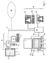
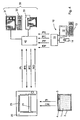
- the image carrier for X-ray information consists of a cassette 2 with an image plate 1 located therein.
- the image plate 1 comprises a carrier layer with a storage phosphor layer 5 applied thereon.
- the storage phosphor layer 5 preferably has a storage phosphor based on BaFBr: Eu or CsBr: Eu up.
- the integrated circuit 3 may be attached to the cassette 2.
- the data transmission between the integrated circuit 3 and the ID station 10 is preferably contactless. In this way, an exact positioning of the image plate 1 and the circuit 3 relative to the ID station 10, as would be required in a contact-type data transmission omitted.
- the contactless data transmission is preferably carried out by means of radio frequency waves (RF waves).
- the ID station 10 has a corresponding first read-write device 11 with an RF transmitter and an RF receiver.
- the integrated circuit 3 is preferably in the form of a so-called RF label, which is also referred to as RF tag, attached to the image plate 1, for example, glued.
- RF tag comprises, in addition to the integrated circuit 3, an antenna designed as a transponder coil.
- the integrated circuit 3 may also be attached to the image plate 1 in the form of a chip card in which an RF tag is inserted into a card-shaped plastic body.
- the smart card is preferably releasably attached to the image panel 1, e.g. by means of a simple plug connection in the edge region of the image plate 1.
- a locking mechanism may be provided, e.g.
- the ID station 10 includes one or more input devices for inputting data which are specific or required, for example, for a patient to be examined, the read-out of the image plate 1 or the further processing of image data read from the image plate 1.
- the input devices include a keyboard 13 with display unit 12, such.
- a card reader 15 for a card 14 on which there are data to be entered.
- the card 14 is a chip card, for example a health insurance card, on which patient-specific data, such as name, address, date of birth and insurance number of a patient are stored.
- the card reader 15 reads out these data from the card 14 and transfers them to a buffer 16 of the ID station 10.
- the data entered via the keyboard 13 are also transferred to the buffer 16.
- the display unit 12 can preferably also be a so-called touchscreen, in which displayed functions and / or data can be selected by touching the corresponding areas of the display.
- the input data is transferred to the first read-write device 11 and written in the memory of the integrated circuit 3 on the optical disk 1.
- the scanner 21 is preferably designed as a so-called line scanner, which has a line-shaped stimulation light source, preferably with laser diodes arranged in a row, and a line-shaped detector, preferably a linear CCD array.
- a line-shaped stimulation light source preferably with laser diodes arranged in a row
- a line-shaped detector preferably a linear CCD array.
- emission light is excited whose intensity corresponds to the X-ray information stored in the storage phosphor layer 5.
- the emission light is detected by the line-shaped detector and converted into corresponding image signals.
- the storage phosphor layer 5 is successively read line by line, a two-dimensional image of the stored X-ray information being obtained.
- the scanner 21 may also be designed as a so-called flying spot scanner, in which a single laser beam is directed onto the storage phosphor layer 5 by a rotating polygon mirror, as a result of which it is scanned point by point along individual lines.
- the read-out device 20 comprises a second read-write device 24 with which data can be read from or written into the integrated circuit 3.
- the second read-write device 24 is also preferably designed for contactless data transmission, in particular by means of RF waves.
- the data read out from the memory of the integrated circuit 3 with the second read-write device 24 are used in particular for controlling the readout of the image plate 1 with the scanner 21 and / or for controlling the deletion of the image plate 1 with the deletion device 23.
- data may be written into the integrated circuit 3 by the second read / write device 24 to preferably update data on the processing status of the optical disk 1, for example, whether the optical disk 1 has already been read out or erased.
- the image data stored in the central memory 40 can then be further processed and / or reproduced in the playback device 30.
- the reproduction device 30 comprises a monitor 31 which can be controlled by means of a keyboard 32a.
- a hardcopy device 33 for example a laser printer, may also be provided for outputting the image data.
- the central memory 40 can optionally be connected to a network 50, in particular to a local area network (LAN). This makes it possible for other systems, in particular other ID stations and / or playback devices, to be able to access the data or image data stored in the central memory 40.
- LAN local area network
- the central memory 40 may be formed as a separate central unit which may be e.g. can be integrated in a central file server. Alternatively, however, the central memory 40 may also be an integral part of the ID station 10, the read-out device 20 or the playback device 30.
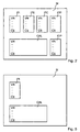
- the version number VN at the beginning of each data group indicates in which data structure the data of a data group is stored. This opens up the possibility of providing different data structures of one and the same data group. This is always necessary if other or additional data is to be stored in the memory M, for example in the case of a new type of image plate or a new type of processing of the image data.
- the individual components of the system e.g. the ID station 10, the read-out device 20 and the playback device 30, respectively, recognize which data is contained in the respective data group and in which data length, sequence etc. this data is present.
- the check sum CS at the end of each data group is derived from the individual data in this data group. Based on the respective checksum CS can be determined whether the data of this data group have been stored or read without error.
- the content of the image carrier data group IPI is additionally provided as a visually readable marker 4 (see FIG Fig. 1 ) is applied to the image plate 1 and / or the cassette 2.
- a visually readable marker 4 see FIG Fig. 1
- a mark 4 may be for example as follows: 301 - 6 ⁇ KBQMF ⁇ 0001 - 20030702 - 1 - 1 - 0 - 1000 - 1000 - 123
- the data taken from the marker 4 can easily be written to the memory of the new integrated circuit at the ID station 10 without requiring a new initialization from the manufacturer of the image plate 1 or cassette 2.
- the data of the marker 4 are read by an operator, entered via the keyboard 13 of the ID station 10 and then written into the memory of the new integrated circuit.
- readable mark 4 represents a particularly simple possibility for additional protection of data stored in the integrated circuit 3.
- a machine-readable mark (not shown) may be provided, for example in the form of a Barcodes or magnetic stripe. To enter the data contained in the machine-readable mark then a corresponding bar code or magnetic stripe reader is required, which forwards the machine-read data to the ID station 10, where they can then be written in the new integrated circuit.
- the patient data group IDP can also be dispensed with if reference codes for patient data are already provided in the processing data group IPP, as described above.
- the appropriate patient data such as Name and / or date of birth and / or sex of the patient, refer to the central memory 40.
- image plates 1 is the mark 4, which represents part of the data stored in the memory M of the integrated circuit 3, in particular data of the image carrier data group IPI, mounted on the back of the carrier layer of the image plate 1.
- the mark 4 is therefore shown in dashed lines.
- Fig. 5 shows a second example of a structure of the data stored in the integrated circuit 3 of the image carrier in the in Fig. 4 illustrated variant of the data flow.
- data of the image carrier and calibration data group IPI or CAL are stored in the memory M.
- IPI and CAL apply the above remarks Fig. 2 corresponding.
Landscapes
- Health & Medical Sciences (AREA)
- Life Sciences & Earth Sciences (AREA)
- Physics & Mathematics (AREA)
- Medical Informatics (AREA)
- General Physics & Mathematics (AREA)
- High Energy & Nuclear Physics (AREA)
- Molecular Biology (AREA)
- Engineering & Computer Science (AREA)
- Pathology (AREA)
- Heart & Thoracic Surgery (AREA)
- Nuclear Medicine, Radiotherapy & Molecular Imaging (AREA)
- Optics & Photonics (AREA)
- Spectroscopy & Molecular Physics (AREA)
- Radiology & Medical Imaging (AREA)
- Biomedical Technology (AREA)
- Biophysics (AREA)
- Surgery (AREA)
- Animal Behavior & Ethology (AREA)
- General Health & Medical Sciences (AREA)
- Public Health (AREA)
- Veterinary Medicine (AREA)
- Apparatus For Radiation Diagnosis (AREA)
- Radiography Using Non-Light Waves (AREA)
- Image Analysis (AREA)
Abstract
Description
Die Erfindung betrifft ein Verfahren zur Bearbeitung eines Bildträgers zur Aufzeichnung von Röntgenaufnahmen gemäß dem Oberbegriff des Anspruchs 1.The invention relates to a method for processing an image carrier for recording X-ray images according to the preamble of
Entsprechende Bildträger werden, insbesondere für medizinische Zwecke, im Bereich der Computer-Radiographie (CR) eingesetzt. Hierbei werden Röntgenaufnahmen in einer Speicherleuchtstoff-Schicht aufgezeichnet, indem die durch ein Objekt, beispielsweise einen Patienten, hindurchtretende Röntgenstrahlung als latentes Bild in der Speicherleuchtstoff-Schicht gespeichert wird. Zum Auslesen der gespeicherten Röntgeninformation wird die Speicherleuchtstoff-Schicht mit Stimulationslicht bestrahlt, wodurch diese zur Aussendung von Emissionslicht angeregt wird, welches von einem optischen Detektor erfasst und in elektrische Signale umgewandelt wird. Die elektrischen Signale können nach Bedarf weiterverarbeitet und auf einem Monitor dargestellt oder an einem entsprechenden Ausgabegerät, wie z. B. einem Drucker, ausgegeben werden. Nach einem Löschvorgang, bei dem etwaige verbliebene Röntgeninformation vollständig aus der Speicherleuchtstoff-Schicht eliminiert wird, steht die Speicherleuchtstoff-Schicht für weitere Röntgenaufnahmen zur Verfügung.Corresponding image carriers are used, in particular for medical purposes, in the field of computer radiography (CR). In this case, X-ray images are recorded in a storage phosphor layer by storing the X-ray radiation passing through an object, for example a patient, as a latent image in the storage phosphor layer. To read the stored X-ray information, the storage phosphor layer is irradiated with stimulation light, whereby it is stimulated to emit emission light, which is detected by an optical detector and converted into electrical signals. The electrical signals can be further processed as needed and displayed on a monitor or to a corresponding output device, such. A printer. After a deletion, in which any remaining X-ray information completely from the Storage phosphor layer is eliminated, the storage phosphor layer is available for further X-ray.
Da Speicherleuchtstoff-Schichten im Allgemeinen unterschiedliche Empfindlichkeiten für Röntgenstrahlung aufweisen, muss bei der Verarbeitung der beim Auslesen des Bildträgers erhaltenen Bildsignale unter anderem die Empfindlichkeit der jeweiligen Speicherleuchtstoff-Schicht für Röntgenstrahlung berücksichtigt werden. Die entsprechenden Daten, die ein Maß für die Empfindlichkeit der Speicherleuchtstoff-Schicht eines Bildträgers für Röntgenstrahlung darstellen, werden im Stand der Technik meist ab Werk auf einem separaten Datenträger mit dem Bildträger mitgeliefert. Dabei kann es bei Verwechslung der einzelnen, im Allgemeinen zu unterschiedlichen Bildträgern gehörenden Datenträger dazu kommen, dass die von einer Speicherleuchtstoff-Schicht eines Bildträgers erhaltenen Bildsignale fälschlicherweise mit den entsprechenden Daten eines anderen Bildträgers korrigiert werden. Dies führt zu einer nicht tolerierbaren Verfälschung der ausgelesenen Röntgeninformation.Since storage phosphor layers generally have different X-radiation sensitivities, the sensitivity of the respective X-ray storage phosphor layer must be taken into account, inter alia, during processing of the image signals obtained when the image carrier is read out. The corresponding data, which represent a measure of the sensitivity of the storage phosphor layer of an image carrier for X-radiation, are supplied in the prior art usually ex works on a separate disk with the image carrier. In the case of confusion of the individual data carriers, which generally belong to different image carriers, it may happen that the image signals obtained from a storage phosphor layer of an image carrier are erroneously corrected with the corresponding data of another image carrier. This leads to an intolerable falsification of the read X-ray information.
Bei den aus dem Stand der Technik bekannten Verfahren bzw. Systemen wird aufgrund der großen Menge an Korrekturdaten relativ viel Zeit benötigt, bis diese für die Bilddatenkorrektur bereitstehen. Darüber hinaus kann es zu Übertragungsfehlern kommen.In the methods or systems known from the prior art, a relatively large amount of time is required due to the large amount of correction data until this ready for image data correction. In addition, transmission errors can occur.
Es ist Aufgabe der vorliegenden Erfindung, ein Verfahren zur Bearbeitung des Bildträgers anzugeben, bei welchem unterschiedliche Empfindlichkeiten des Bildträgers für Röntgenstrahlung zeitsparend und mit erhöhter Zuverlässigkeit zur Verfügung gestellt werden.It is an object of the present invention to provide a method for processing the image carrier, in which different sensitivities of the image carrier for X-radiation are provided in a time-saving manner and with increased reliability.
Diese Aufgabe wird durch das Verfahren gemäß Anspruch 1 gelöst.This object is achieved by the method according to
Das erfindungsgemäße Verfahren zur Bearbeitung des Bildträgers ist dadurch gekennzeichnet, dass der Bildträger einen elektronischen Speicher zur Speicherung von Kalibrierdaten des Bildträgers umfasst, welche ein Maß für die Empfindlichkeit des Bildträgers für Röntgenstrahlung darstellen und bei einer Verarbeitung von Bildsignalen, welche bei einem Auslesen der Röntgeninformation aus dem Bildträger erhalten werden, herangezogen werden können, und die Kalibrierdaten nach einem ersten Auslesen der Kalibrierdaten aus dem elektronischen Speicher des Bildträgers in einem Speicher, insbesondere in einem Zentralspeicher oder in einem Speicher einer Auslesevorrichtung, gespeichert werden.The inventive method for processing the image carrier is characterized in that the image carrier comprises an electronic memory for storing calibration data of the image carrier, which represent a measure of the sensitivity of the image carrier for X-radiation and in a processing of image signals, which in a readout of the X-ray information The calibration data can be stored after a first reading of the calibration data from the electronic memory of the image carrier in a memory, in particular in a central memory or in a memory of a read-out device.
Bei einer erneuten Bearbeitung desselben Bildträgers werden dann die nach dem ersten Auslesen gespeicherten Kalibrierdaten dieses Bildträgers aus dem Speicher, insbesondere dem Speicher der Auslesevorrichtung bzw. dem Zentralspeicher, gelesen. Die Kalibrierdaten stehen dadurch in kürzerer Zeit für die Bildsignalverarbeitung zur Verfügung als bei einem erneuten Auslesen des zweidimensionalen Datensatzes aus dem elektronischen Speicher des Bildträgers. Auch etwaige Übertragungsfehler beim Auslesen des Datensatzes aus dem elektronischen Speicher können dadurch vermieden werden.If the same image carrier is processed again, the calibration data of this image carrier stored after the first read out are then read from the memory, in particular the memory of the read device or the central memory. As a result, the calibration data are available for the image signal processing in a shorter time than when the two-dimensional data record is read again from the electronic memory of the image carrier. Also possible transmission errors when reading the record from the electronic memory can be avoided.
Vorzugsweise erfolgt dabei das erste Auslesen der Kalibrierdaten des Bildträgers aus dem elektronischen Speicher des Bildträgers in der Auslesevorrichtung.The first readout of the calibration data of the image carrier preferably takes place from the electronic memory of the image carrier in the read-out device.
Der Bildträger weist einen elektronischen Speicher zur Speicherung von Kalibrierdaten des Bildträgers auf, wobei die Kalibrierdaten ein Maß für die Empfindlichkeit des Bildträgers für Röntgenstrahlung darstellen und bei der Verarbeitung von Bildsignalen, welche bei einem Auslesen der Röntgeninformation aus dem Bildträger erhalten werden, herangezogen werden können.The image carrier has an electronic memory for storing calibration data of the image carrier, wherein the calibration data represent a measure of the sensitivity of the image carrier for X-radiation and in the processing of image signals, which are obtained in a readout of the X-ray information from the image carrier, can be used.
Durch die Speicherung der Kalibrierdaten in dem auf dem Bildträger befindlichen elektronischen Speicher kann eine zusätzliche Übermittlung der Kalibrierdaten über einen zusätzlichen Datenträger entfallen. Hierdurch wird außerdem eine Verwechslung einzelner Datenträger ausgeschlossen und damit die Zuverlässigkeit bei der Berücksichtigung unterschiedlicher Empfindlichkeiten der Bildträger erhöht.By storing the calibration data in the electronic memory located on the image carrier, an additional transmission of the calibration data via an additional data carrier can be dispensed with. As a result, a confusion of individual media is also excluded and thus increases the reliability in the consideration of different sensitivities of the image carrier.
Der elektronische Speicher ist vorzugsweise als integrierter elektronischer Schaltkreis mit einem nicht-flüchtigen Speicher ausgebildet, beispielsweise als ROM, PROM, EPROM oder EEPROM.The electronic memory is preferably designed as an integrated electronic circuit with a non-volatile memory, for example as ROM, PROM, EPROM or EEPROM.
Vorzugsweise stellen die Kalibrierdaten des Bildträgers ein Maß für eine über eine Speicherleuchtstoff-Schicht des Bildträgers lokal veränderliche Empfindlichkeit des Bildträgers für Röntgenstrahlung dar. Dadurch werden nicht nur unterschiedliche Empfindlichkeiten einzelner Bildträger berücksichtigt, sonder auch individuell auftretende Variationen der Empfindlichkeit über die gesamte Fläche der Speicherleuchtstoff-Schicht eines einzelnen Bildträgers. Die Genauigkeit der Kalibrierung wird dadurch erhöht.Preferably, the calibration data of the image carrier is a measure of a storage phosphor layer of the image carrier locally variable sensitivity of the image carrier for X-ray. Not only different sensitivities of individual image carriers are considered, but also individually occurring variations in sensitivity over the entire surface of the storage phosphor Layer of a single image carrier. The accuracy of the calibration is thereby increased.
Die Kalibrierdaten, welche ein Maß für die lokal veränderliche Empfindlichkeit des Bildträgers für Röntgenstrahlung darstellen, sind vorzugsweise in einem zweidimensionalen Datenfeld im elektronischen Speicher des Bildträgers gespeichert. Hierdurch wird eine übersichtliche Korrelation einzelner Bereiche der Speicherleuchtstoff-Schicht mit deren jeweiliger Empfindlichkeit erreicht.The calibration data, which represent a measure of the locally variable sensitivity of the image carrier for X-radiation, are preferably stored in a two-dimensional data field in the electronic memory of the image carrier. As a result, a clear correlation of individual areas of the storage phosphor layer is achieved with their respective sensitivity.
In einer weiteren Ausgestaltung ist vorgesehen, dass die Kalibrierdaten des Bildträgers die lokal veränderliche Empfindlichkeit des Bildträgers in einzelnen Bereichen des Bildträgers wiedergeben, wobei die einzelnen Bereiche den einzelnen Bildpunkten (Pixel) entsprechen, die bei einem Auslesen der im Bildträger gespeicherten Röntgeninformation erhalten werden. Hierdurch wird eine pixelgenaue Kalibrierung ermöglicht, die lokal unterschiedliche Empfindlichkeiten mit sehr hoher Genauigkeit berücksichtigt.In a further embodiment, it is provided that the calibration data of the image carrier reproduce the locally variable sensitivity of the image carrier in individual regions of the image carrier, wherein the individual regions correspond to the individual pixels that are obtained when reading out the X-ray information stored in the image carrier. This allows a pixel-accurate calibration, which takes into account locally different sensitivities with very high accuracy.
In einer alternativen Ausgestaltung kann aber auch vorgesehen sein, dass die Kalibrierdaten des Bildträgers die lokal veränderliche Empfindlichkeit des Bildträgers in einzelnen Bereichen des Bildträgers wiedergeben, wobei die einzelnen Bereiche größer sind als die einzelnen Bildpunkte (Pixel), die bei einem Auslesen der im Bildträger gespeicherten Röntgeninformation erhalten werden. Auf diese Weise kann der Speicherplatzbedarf für die Kalibrierdaten im elektronischen Speicher stark reduziert werden, wobei gleichzeitig lokal unterschiedliche Empfindlichkeiten dennoch mit einer hohen Genauigkeit berücksichtigt werden.In an alternative embodiment, however, it may also be provided that the calibration data of the image carrier reproduce the locally variable sensitivity of the image carrier in individual regions of the image carrier, wherein the individual regions are larger than the individual pixels that are stored in a readout of the images stored in the image carrier X-ray information can be obtained. In this way, the memory requirements for the calibration data in the electronic memory can be greatly reduced, while at the same time locally different sensitivities are taken into account with a high degree of accuracy.
In einer weiteren Ausgestaltung der Erfindung sind die Kalibrierdaten des Bildträgers in einer Kalibrierungs-Datengruppe im elektronischen Speicher des Bildträgers gespeichert. Dadurch wird sowohl eine übersichtliche Aufteilung des Speicherinhalts erreicht als auch ein einfacherer Zugriff auf die Kalibrierdaten der Kalibrier-Datengruppe ermöglicht.In a further embodiment of the invention, the calibration data of the image carrier are stored in a calibration data group in the electronic memory of the image carrier. As a result, both a clear division of the memory content is achieved as well as easier access to the calibration data of the calibration data group allows.
In einer weiteren vorteilhaften Ausgestaltung umfasst der Bildträger eine Bildplatte zur Speicherung der Röntgeninformation, wobei der elektronische Speicher vorzugsweise an der Bildplatte angebracht ist. Dadurch wird eine sichere Zuordnung der im elektronischen Speicher gespeicherten Kalibrierdaten zur zugehörigen Bildplatte gewährleistet.In a further advantageous embodiment, the image carrier comprises an image plate for storing the X-ray information, wherein the electronic memory is preferably attached to the image plate. This ensures a secure assignment of the calibration data stored in the electronic memory to the associated image plate.
In einer Ausführung dieser Variante ist vorgesehen, dass die Bildplatte eine Trägerschicht mit einer auf der Vorderseite der Trägerschicht befindlichen Speicherleuchtstoff-Schicht umfasst und der elektronische Speicher in einem Randbereich der Trägerschicht, insbesondere außerhalb der Speicherleuchtstoff-Schicht, und/oder an der der Vorderseite gegenüberliegenden Rückseite der Trägerschicht angebracht ist. Hierdurch wird eine Beeinträchtigung der Speichereigenschaften der Speicherleuchtstoff-Schicht durch den elektronischen Speicher vermieden.In one embodiment of this variant, it is provided that the image plate comprises a carrier layer with a storage phosphor layer located on the front side of the carrier layer and the electronic memory is located in an edge region of the carrier layer, in particular outside the storage phosphor layer, and / or on the front side Rear side of the carrier layer is attached. As a result, an impairment of the storage properties of the storage phosphor layer is avoided by the electronic memory.
In der Regel umfasst der Bildträger neben der Bildplatte eine Kassette, welche die Bildplatte unter Abschirmung von Umgebungslicht aufnehmen kann. Ist der elektronische Speicher zur kontaktlosen Datenübertragung ausgebildet, kann sein Speicherinhalt mit einem entsprechenden RF-Leser auch von der Außenseite der Kassette durch die Kassettenwand hindurch ausgelesen werden.As a rule, the image carrier next to the image plate comprises a cassette which can receive the image plate while shielding from ambient light. If the electronic memory is designed for contactless data transmission, this can be Memory contents are also read with a corresponding RF reader from the outside of the cassette through the cassette wall.
In einer alternativen Ausgestaltung der Erfindung ist der elektronische Speicher an der Kassette angebracht. Die Kassette muss in diesem Fall nicht geöffnet und die Bildplatte nicht entnommen werden, wenn der elektronische Speicher nur durch galvanische Kontaktierung ausgelesen werden kann.In an alternative embodiment of the invention, the electronic memory is attached to the cassette. In this case, the cassette does not have to be opened and the image plate not removed, if the electronic memory can only be read out by galvanic contacting.
Vorteilhafterweise sind die Kalibrierdaten im elektronischen Speicher des Bildträgers in komprimierter Form gespeichert. Hierdurch kann der Speicherplatzbedarf zum Teil stark reduziert werden. Als Datenkomprimierungsverfahren eignet sich beispielsweise JPEG.Advantageously, the calibration data are stored in the electronic memory of the image carrier in compressed form. As a result, the storage space requirement can be greatly reduced. As a data compression method, for example, JPEG is suitable.
Ein entsprechendes System zur Bearbeitung eines Bildträgers zur Speicherung von Röntgeninformation besteht aus mindestens einem Bildträger und mindestens einer Vorrichtung zur Bearbeitung des Bildträgers und/oder zur Weiterverarbeitung und/oder Wiedergabe der im Bildträger gespeicherten Röntgeninformation und zeichnet sich dadurch aus, dass der Bildträger einen elektronischen Speicher zur Speicherung von Kalibrierdaten des Bildträgers umfasst, welche ein Maß für die Empfindlichkeit des Bildträgers für Röntgenstrahlung darstellen und bei einer Verarbeitung von Bildsignalen, welche bei einem Auslesen der Röntgeninformation aus dem Bildträger erhalten werden, herangezogen werden können.A corresponding system for processing an image carrier for storing X-ray information consists of at least one image carrier and at least one device for processing the image carrier and / or for further processing and / or reproduction of the X-ray information stored in the image carrier and is characterized in that the image carrier has an electronic memory for storing calibration data of the image carrier, which represent a measure of the sensitivity of the image carrier for X-radiation and can be used in a processing of image signals which are obtained when reading the X-ray information from the image carrier.
Hierbei ist eine Vorrichtung als Auslesevorrichtung ausgebildet, welche die im Bildträger gespeicherte Röntgeninformation auslesen und dabei entsprechende Bildsignale erzeugen kann und die erzeugten Bildsignale unter Heranziehung der im elektronischen Speicher gespeicherten Kalibrierdaten des Bildträgers verarbeiten kann. Vorzugsweise ist die Auslesevorrichtung mit einem entsprechenden Lesegerät ausgestattet, mit dem die im elektronischen Speicher des Bildträgers gespeicherten Kalibrierdaten des Bildträgers gelesen werden können.In this case, a device is designed as a read-out device, which can read the X-ray information stored in the image carrier and thereby generate corresponding image signals and can process the generated image signals by using the calibration data of the image carrier stored in the electronic memory. Preferably, the readout device is equipped with a corresponding reader, with which the stored in the electronic memory of the image carrier calibration data of the image carrier can be read.
Weitere Merkmale und Vorteile der Erfindung ergeben sich aus der folgenden Beschreibung bevorzugter Ausführungsformen und Anwendungsbeispiele, wobei Bezug auf die beigefügten Figuren genommen wird.Further features and advantages of the invention will become apparent from the following description of preferred embodiments and application examples, reference being made to the accompanying figures.
Es zeigen:
- Fig. 1
- ein System zur Bearbeitung eines Bildträgers für Röntgeninformation;
- Fig. 2
- ein erstes Beispiel einer Struktur der im integrierten Schaltkreis des Bildträgers gespeicherten Daten;
- Fig. 3
- eine schematische Darstellung einer ersten Variante des Datenflusses zwischen einzelne Komponenten des in
Fig. 1 dargestellten Systems; - Fig. 4
- eine schematische Darstellung einer zweiten Variante des Datenflusses zwischen einzelnen Komponenten des in
Fig. 1 dargestellten Systems; und - Fig. 5
- ein zweites Beispiel einer Struktur der im integrierten Schaltkreis des Bildträgers gespeicherten Daten.
- Fig. 1
- a system for processing an image carrier for x-ray information;
- Fig. 2
- a first example of a structure of the data stored in the integrated circuit of the image carrier;
- Fig. 3
- a schematic representation of a first variant of the data flow between individual components of in
Fig. 1 represented system; - Fig. 4
- a schematic representation of a second variant of the data flow between individual components of in
Fig. 1 represented system; and - Fig. 5
- A second example of a structure of the data stored in the integrated circuit of the image carrier.
Der Bildträger für Röntgeninformation besteht aus einer Kassette 2 mit einer darin befindlichen Bildplatte 1. Die Bildplatte 1 umfasst eine Trägerschicht mit einer darauf aufgebrachten Speicherleuchtstoff-Schicht 5. Die Speicherleuchtstoff-Schicht 5 weist vorzugsweise einen Speicherleuchtstoff auf der Basis von BaFBr:Eu oder CsBr:Eu auf.The image carrier for X-ray information consists of a
Die Bildplatte 1 ist mit einem integrierten Schaltkreis 3 versehen, der einen Schreib-Lese-Speicher umfasst, in welchen Daten geschrieben und aus welchem Daten gelesen werden können. Um die Speicherfunktion der Speicherleuchtstoff-Schicht 5 nicht zu beeinträchtigen, wird der integrierte Schaltkreis 3 vorzugsweise an der Rückseite oder - wie im dargestellten Beispiel - im Randbereich der Bildplatte 1 angeordnet.The
Alternativ oder zusätzlich kann der integrierter Schaltkreis 3 an der Kassette 2 angebracht sein. Die folgenden Ausführungen, die sich auf einen an der Bildplatte 1 befindlichen integrierten Schaltkreis 3 beziehen, gelten auch für diese Alternative entsprechend.Alternatively or additionally, the
Nach einer Röntgenaufnahme wird die in der Kassette 2 befindliche Bildplatte 1, in deren Speicherleuchtstoff-Schicht 5 Röntgeninformation gespeichert ist, zur ID-Station 10 gebracht, um Daten aus dem und/oder in den integrierten Schaltkreis 3 zu lesen bzw. zu schreiben. Die Datenübertragung zwischen dem integrierten Schaltkreis 3 und der ID-Station 10 erfolgt vorzugsweise kontaktlos. Hierdurch kann eine exakte Positionierung der Bildplatte 1 und des Schaltkreises 3 relativ zur ID-Station 10, wie sie bei einer kontaktbehafteten Datenübertragung erforderlich wäre, entfallen. Die kontaktlose Datenübertragung erfolgt vorzugsweise mittels Radiofrequenz-Wellen (RF-Wellen). Zu diesem Zweck weist die ID-Station 10 eine entsprechende erste Schreib-Lese-Einrichtung 11 mit einem RF-Sender und einem RF-Empfänger auf.After an X-ray, the
Der integrierte Schaltkreis 3 ist vorzugsweise in Form eines sogenannten RF-Etiketts, welches auch als RF-Tag bezeichnet wird, an der Bildplatte 1 angebracht, beispielsweise aufgeklebt. Ein solches RF-Tag umfasst neben dem integrierten Schaltkreis 3 eine als Transponderspule ausgebildete Antenne. Statt als RF-Tag kann der integrierte Schaltkreis 3 auch in Form einer Chipkarte, bei welcher ein RF-Tag in einen kartenförmigen Plastikkörper eingebracht ist, an der Bildplatte 1 angebracht sein. Die Chipkarte wird vorzugsweise lösbar an der Bildplatte 1 befestigt, z.B. mittels einer einfachen Steckverbindung im Randbereich der Bildplatte 1. Zur zusätzlichen Sicherung der Chipkarte kann ein Arretiermechanismus vorgesehen sein, z.B. ein Schnappmechanismus, bei welchem die Chipkarte durch Zuschnappen arretiert wird. Diese Befestigung der Chipkarte an der Bildplatte 1 ist einerseits einfach und sicher und vereinfacht andererseits den - beispielsweise im Falle eines Defekts des integrierten Schaltkreises 3 erforderlichen - Austausch der Chipkarte gegen eine andere.The
Die Bildplatte 1 ist mit einer mit dem bloßen Auge lesbaren Markierung 4 versehen, welche zumindest einen Teil der im Speicher des integrierten Schaltkreises 3 gespeicherten Daten, insbesondere für die Bildplatte 1 spezifische Daten, repräsentiert und vorzugsweise als alphanumerische Zeichenfolge ausgebildet ist. Hierdurch sind bei einem Defekt des integrierten Schaltkreises 3, bei dem die darin gespeicherten Daten im Allgemeinen nicht mehr ausgelesen werden können, die in der Markierung 4 enthaltenen Daten weiterhin zugänglich. Der defekte integrierte Schaltkreis 3 kann in diesem Fall gegen einen neuen ausgetauscht werden, in welchen dann die in der Markierung 4 enthaltenen Daten geschrieben werden. Hierzu werden die Daten der Markierung 4 von einem Bediener gelesen, an der ID-Station 10 eingegeben und schließlich in den neuen integrierten Schaltkreis geschrieben. Mit Hilfe der Markierung 4 wird damit auf einfache Weise sichergestellt, dass der im integrierten Schaltkreis 3 gespeicherte und in der Markierung 3 enthaltene Teil der Daten auch bei einem Defekt des Schaltkreises 3 nicht verlorengeht.The
Alternativ oder zusätzlich kann eine derart ausgestaltete Markierung 4 auch an der Kassette 2 angebracht sein. Das Vorgehen bei einem Defekt des integrierten Schaltkreises erfolgt in analoger Weise.Alternatively or additionally, a
Die ID-Station 10 umfasst eine oder mehrere Eingabeeinrichtungen zur Eingabe von Daten, welche beispielsweise für einen zu untersuchenden Patienten, das Auslesen der Bildplatte 1 oder die Weiterverarbeitung von aus der Bildplatte 1 ausgelesenen Bilddaten spezifisch bzw. erforderlich sind. Im dargestellten Beispiel umfassen die Eingabeeinrichtungen eine Tastatur 13 mit Anzeigeeinheit 12, wie z. B. einen Monitor, sowie einen Kartenleser 15 für eine Karte 14, auf welcher sich einzugebende Daten befinden. Insbesondere handelt es sich bei der Karte 14 um eine Chipkarte, beispielsweise eine Krankenversicherungskarte, auf welcher patientenspezifische Daten, wie z.B. Name, Adresse, Geburtsdatum und Versicherungsnummer eines Patienten, gespeichert sind. Der Kartenleser 15 liest diese Daten aus der Karte 14 aus und übergibt sie an einen Zwischenspeicher 16 der ID-Station 10. Auch die über die Tastatur 13 eingegebenen Daten werden an den Zwischenspeicher 16 übergeben. Bei der Anzeigeeinheit 12 kann es sich vorzugsweise auch um einen sog. Touchscreen handeln, bei welchem angezeigte Funktionen und/oder Daten durch Berührung der entsprechenden Bereiche der Anzeige ausgewählt werden können.The
Vom Zwischenspeicher 16 aus werden die eingegebenen Daten an die erste Schreib-Lese-Einrichtung 11 übergeben und in den Speicher des integrierten Schaltkreises 3 auf der Bildplatte 1 geschrieben.From the
Anstelle der eingegebenen Daten selbst kann ein diesen Daten zugeordneter Referenzcode in den Speicher des integrierten Schaltkreises 3 geschrieben werden, während die eingegebenen Daten zusammen mit dem ihnen zugeordneten Referenzcode im Zwischenspeicher 16 und/oder im Zentralspeicher 40 gespeichert werden. Auf dieses Verfahren wird weiter unten noch näher eingegangen.Instead of the input data itself, a reference code associated with this data may be written into the memory of the
Anschließend wird die Kassette 2 mit der darin befindlichen Bildplatte 1 zur Auslesevorrichtung 20 gebracht, wo die Kassette 2 automatisch geöffnet, die Bildplatte 1 entnommen und in das Innere der Auslesevorrichtung 20 eingezogen wird. In der hier dargestellten Position ist die Bildplatte 1 bereits vollständig aus der Kassette herausgezogen und im Innern der Auslesevorrichtung 20 arretiert. In dieser Position wird sie von einem Scanner 21, welcher mit einem geeigneten Transportmechanismus 22 in Transportrichtung T über die Bildplatte 1 bewegt wird, ausgelesen.Subsequently, the
Der Scanner 21 ist vorzugsweise als sog. Zeilenscanner ausgebildet, welcher eine zeilenförmige Stimulationslichtquelle, vorzugsweise mit in einer Reihe angeordneten Laserdioden, und einen zeilenförmigen Detektor, vorzugsweise ein lineares CCD-Array, aufweist. Während der Bewegung des Scanners 21 über die Bildplatte 1 wird diese mit dem Licht der Stimulationslichtquelle zeilenweise bestrahlt, wobei in der Speicherleuchtstoff-Schicht 5 Emissionslicht angeregt wird, dessen Intensität der in der Speicherleuchtstoff-Schicht 5 gespeicherten Röntgeninformation entspricht. Das Emissionslicht wird mit dem zeilenförmigen Detektor erfasst und in entsprechende Bildsignale umgewandelt. Durch die kontinuierliche Bewegung des Scanners 21 in Transportrichtung T über die Bildplatte 1 wird die Speicherleuchtstoff-Schicht 5 sukzessive zeilenweise ausgelesen, wobei ein zweidimensionales Abbild der gespeicherten Röntgeninformation erhalten wird.The
Alternativ kann der Scanner 21 auch als sog. Flying Spot-Scanner ausgebildet sein, bei welchem ein einzelner Laserstrahl durch einen rotierenden Polygonspiegel auf die Speicherleuchtstoff-Schicht 5 gelenkt wird, wodurch diese entlang einzelner Zeilen punktweise abgetastet wird.Alternatively, the
Nachdem die Bildplatte 1 vollständig ausgelesen worden ist, wird diese wieder automatisch zurück in die Kassette 2 befördert. Dabei passiert sie eine Löscheinrichtung 23, an welcher etwaige restliche Röntgeninformationen in der Bildplatte 1 durch Bestrahlung der Speicherleuchtstoff-Schicht 5 mit Löschstrahlung gelöscht werden. Die Löscheinrichtung 23 umfasst hierzu eine Strahlungsquelle mit einem - verglichen mit der Stimulationslichtquelle - breitbandigerem Spektrum und einen geeigneten Reflektor zur Reflexion von Löschstrahlung auf die Speicherleuchtstoff-Schicht 5 der Bildplatte 1.After the
Die Auslesevorrichtung 20 umfasst eine zweite Schreib-Lese-Einrichtung 24, mit welcher Daten aus dem bzw. in den integrierten Schaltkreis 3 gelesen bzw. geschrieben werden können. Wie die erste Schreib-Lese-Einrichtung 11 der ID-Station 10 ist auch die zweite Schreib-Lese-Einrichtung 24 vorzugsweise zur kontaktlosen Datenübertragung, insbesondere mittels RF-Wellen, ausgebildet. Die mit der zweiten Schreib-Lese-Einrichtung 24 aus dem Speicher des integrierten Schaltkreises 3 ausgelesenen Daten werden insbesondere zur Steuerung des Auslesens der Bildplatte 1 mit dem Scanner 21 und/oder zur Steuerung des Löschens der Bildplatte 1 mit der Löscheinrichtung 23 herangezogen. Darüber hinaus können mit der zweiten Schreib-Lese-Einrichtung 24 Daten in den integrierten Schaltkreis 3 geschrieben werden, um vorzugsweise Daten zum Bearbeitungsstatus der Bildplatte 1 - beispielsweise, ob die Bildplatte 1 bereits ausgelesen bzw. gelöscht worden ist - zu aktualisieren.The read-out
Beim zeilenweisen Auslesen der Bildplatte 1 mit dem Scanner 21 werden Bilddaten erzeugt, welche die in der Bildplatte 1 gespeicherte Röntgeninformation repräsentieren. Diese Bilddaten werden über einen ersten Datenbus 25, insbesondere einen seriellen Datenbus, wie z.B. einen sog. Fire Wire, an den Zentralspeicher 40 übertragen und dort gespeichert.When the
Die im Zentralspeicher 40 gespeicherten Bilddaten können dann in der Wiedergabevorrichtung 30 weiterverarbeitet und/oder wiedergegeben werden. Zu diesem Zweck umfasst die Wiedergabevorrichtung 30 einen mittels einer Tastatur 32 a n-steuerbaren Monitor 31. Alternativ oder zusätzlich kann auch ein Hardcopygerät 33, beispielsweise ein Laserdrucker, zur Ausgabe der Bilddaten vorgesehen sein.The image data stored in the
Der Zentralspeicher 40 kann optional an einem Netzwerk 50, insbesondere an einem lokalen Netzwerk (LAN), angeschlossen sein. Hierdurch wird ermöglicht, dass von anderen Systemen aus, insbesondere von anderen ID-Stationen und/oder Wiedergabevorrichtungen aus, auf die im Zentralspeicher 40 abgespeicherten Daten bzw. Bilddaten zugegriffen werden kann.The
Der Zentralspeicher 40 kann als separate zentrale Einheit ausgebildet sein, welche z.B. in einem zentralen File-Server integriert sein kann. Alternativ kann der Zentralspeicher 40 aber auch integraler Bestandteil der ID-Station 10, der Auslesevorrichtung 20 oder der Wiedergabevorrichtung 30 sein.The
Die im Speicher M gespeicherten Daten sind in unterschiedlichen Datengruppen IPI, IPS, IPC, IPP, CAL und IDP zusammengefasst und dort jeweils als ASCII-String abgelegt. Jeder Datengruppe ist eine Versionsnummer VN sowie eine Prüfsumme CS zugeordnet.The data stored in the memory M are summarized in different data groups IPI, IPS, IPC, IPP, CAL and IDP and stored there each as an ASCII string. Each data group is assigned a version number VN and a checksum CS.
Die am Beginn jeder Datengruppe stehende Versionsnummer VN gibt an, in welcher Datenstruktur die Daten einer Datengruppe abgelegt sind. Hierdurch wird die Möglichkeit eröffnet, unterschiedliche Datenstrukturen ein und derselben Datengruppe vorzusehen. Dies ist immer dann erforderlich, wenn andere oder zusätzliche Daten im Speicher M abgelegt werden sollen, beispielsweise bei einem neuen Bildplattentyp oder einer neuen Art der Weiterverarbeitung der Bilddaten. Anhand der Versionsnummer VN einer Datengruppe können die einzelnen Komponenten des Systems, z.B. die ID-Station 10, die Auslesevorrichtung 20 bzw. die Wiedergabevorrichtung 30, erkennen, welche Daten in der jeweiligen Datengruppe enthalten sind und in welcher Datenlänge, Reihenfolge usw. diese Daten vorliegen.The version number VN at the beginning of each data group indicates in which data structure the data of a data group is stored. This opens up the possibility of providing different data structures of one and the same data group. This is always necessary if other or additional data is to be stored in the memory M, for example in the case of a new type of image plate or a new type of processing of the image data. Based on the version number VN of a data group, the individual components of the system, e.g. the
Die am Ende jeder Datengruppe stehende Prüfsumme CS wird aus den einzelnen Daten dieser Datengruppe abgeleitet. Anhand der jeweiligen Prüfsumme CS kann festgestellt werden, ob die Daten dieser Datengruppe fehlerfrei gespeichert bzw. gelesen worden sind. Als Prüfsumme CS dient vorzugsweise der Rest der Division der Summe Σ der Zahlenwerte aller in dieser Datengruppe enthaltenen Bytes durch 256, also ![]()
![]()
Im Folgenden wird die Struktur und die Funktion der einzelnen Datengruppen IPI, IPS, IPC, IPP, CAL und IDP näher erläutert.The structure and function of the individual data groups IPI, IPS, IPC, IPP, CAL and IDP are explained in more detail below.
Eine Bildträger-Datengruppe IPI enthält spezifische Daten der Bildplatte 1 und/oder der Kassette 2. Diese Daten werden bei der Herstellung der Bildplatte 1 bzw. der Kassette 2 im Speicher M gespeichert und bleiben bei der Bearbeitung der Bildplatte 1 bzw. der Kassette 2 an der ID-Station 10 und/oder in der Auslesevorrichtung 20 unverändert, d.h. an der ID-Station 10 bzw. in der Auslesevorrichtung 20 werden die in der Bildträger-Datengruppe IPI gespeicherten Daten ausschließlich gelesen. Neben der Versionsnummer VN und der Prüfsumme CS umfasst die Bildträger-Datengruppe IPI folgende Daten:
- Initialisierungsdatum: entspricht dem Datum, an welchem die Daten der Bildträger-Datengruppe IPI in den Speicher
M der Bildplatte 1 geschrieben wurden; - Bildplatten-Seriennummer: dient zur eindeutigen Identifizierung der Bildplatte 1 und ist vorzugsweise aus einem die jeweilige Produktcharge der Bildplatte 1 identifizierenden Code und einer laufenden Nummer zusammengesetzt;
- Bildplattengröße;
- Größe einer auszulesenden Fläche auf der
Bildplatte 1; - Bildplattentyp: z.B. Bildplatte auf der Basis von pulverförmigen oder nadelförmigen Speicherleuchtstoffen, wie z.B. sogenannte Powder-IP bzw. Needle-IP;
- Bildplatten-Empfindlichkeit;
- Bildplatten-Löscheigenschaft: z.B. als Maß für die Dauer und/oder Intensität des von einer
Löscheinrichtung 23 abgegebenen Lichts.
- Initialization date: corresponds to the date on which the data of the image carrier data group IPI was written in the memory M of the
image plate 1; - Image plate serial number: serves to uniquely identify the
image plate 1 and is preferably composed of a code identifying the respective product batch of theimage plate 1 and a sequence number; - Image plate size;
- Size of a surface to be read on the
image plate 1; - Image plate type: eg image plate based on powdered or acicular storage phosphors, such as so-called Powder-IP or Needle-IP;
- Optical disc sensitivity;
- Image plate erasure characteristic: eg as a measure of the duration and / or intensity of the light emitted by a
deletion device 23.
Vorzugsweise wird der Inhalt der Bildträger-Datengruppe IPI zusätzlich als visuell lesbare Markierung 4 (siehe ![]()
![]()
Die ersten drei (301) sowie die letzten drei (123) Zeichen beinhalten die Versionsnummer VN bzw. die Prüfsumme CS. Nach der Versionsnummer VN folgen die Bildplatten-Seriennummer (6KBQMF0001), das Initialisierungsdatum (20030702), Werte für die Bildplattengröße (1), die Größe (1) der auszulesenden Fläche der Bildplatte sowie den Bildplattentyp (0), die Bildplatten-Empfindlichkeit (1000) und schließlich die Bildplatten-Löscheigenschaft (1000).The first three (301) as well as the last three (123) characters contain the version number VN or the checksum CS. The version number VN is followed by the image plate serial number (6KBQMF0001), the initialization date (20030702), the image plate size (1), the size (1) of the image plate to be read and the image plate type (0), the image plate sensitivity (1000 ) and finally the optical disk erase feature (1000).
Die der Markierung 4 entnommenen Daten können an der ID-Station 10 auf einfache Weise in den Speicher des neuen integrierten Schaltkreises geschrieben werden, ohne dass eine neue Initialisierung beim Hersteller der Bildplatte 1 bzw. Kassette 2 erforderlich wäre. Im einfachsten Fall werden die Daten der Markierung 4 von einem Bediener gelesen, über die Tastatur 13 der ID-Station 10 eingegeben und anschließend in den Speicher des neuen integrierten Schaltkreises geschrieben.The data taken from the
Die oben beschriebene visuell, d.h. mit dem menschlichen Auge, lesbare Markierung 4 stellt eine besonders einfache Möglichkeit zur zusätzlichen Sicherung von im integrierten Schaltkreis 3 gespeicherten Daten dar. Selbstverständlich kann anstelle einer visuell lesbaren Markierung alternativ oder zusätzlich eine maschinell lesbare Markierung (nicht dargestellt) vorgesehen sein, beispielsweise in Form eines Barcodes oder Magnetstreifens. Zur Eingabe der in der maschinell lesbaren Markierung enthaltenen Daten ist dann ein entsprechendes Barcode- bzw. Magnetstreifenlesegerät erforderlich, das die maschinell eingelesenen Daten an die ID-Station 10 weiterleitet, wo diese dann in den neuen integrierten Schaltkreis geschrieben werden können.The above described visually, i. With the human eye,
Die Daten einer Zustands-Datengruppe IPS betreffen den jeweiligen Bearbeitungszustand der Bildplatte 1 bzw. der Kassette 2 und werden sowohl in der ID-Station 10 als auch in der Auslesevorrichtung 20 geändert. Neben der Versionsnummer VN und der Prüfsumme CS umfasst diese Datengruppe folgende Daten:
- Bildplattenstatus: z.B. ob die
Bildplatte 1 bereits initialisiert ist (d.h. Daten der Bildträger-Datengruppe IPI im Speicher M gespeichert sind) und/oder ein Röntgenbild bereits aufgenommen, gelöscht bzw. noch zu löschen ist; - Bildplattenzyklen: Gesamtzahl von Röntgenaufnahmen
mit dieser Bildplatte 1. Diese Gesamtzahl wird nach jedem Auslesevorgang oder Löschvorgang in derAuslesevorrichtung 20um den Wert 1 erhöht; - Auslesen unter Biegung: Anzahl der Bildplattenzyklen, in
welchen die Bildplatte 1 während des Auslesevorgangs gekrümmt wird. Diese Zahl ist ein Maß für den Abnutzungs- und/oder Beschädigungsgrad einerBildplatte 1. Dieser Eintrag kann beispielsweise bei Systemen entfallen, in welchen die Bildplatte während des Auslesens auf einer festen, ebenen Unterlage aufliegt und folglich nicht gebogen wird.
- Image disk status: eg whether the
image disk 1 has already been initialized (ie data of the image carrier data group IPI are stored in the memory M) and / or an X-ray image has already been recorded, deleted or still to be deleted; - Image Plate Cycles: Total Number of X-ray Images with This
Image Plate 1. This total number is incremented by 1 after each read or erase operation in thereadout device 20; - Bending Readout: Number of optical disk cycles in which the
optical disk 1 is curved during the read operation. This number is a measure for the wear and / or damage level of animage plate 1. This entry can be omitted, for example, in systems in which the image plate rests during reading on a solid, flat surface and is therefore not bent.
Eine Steuerungs-Datengruppe IPC umfasst alle für eine Röntgenaufnahme spezifischen Daten, die für das Auslesen der Bildplatte 1 in der Auslesevorrichtung 20 erforderlich sind. Die Auslesevorrichtung 20 greift dabei ausschließlich lesend auf die in der Steuerungs-Datengruppe IPC gespeicherten Daten zu. Neben der Versionsnummer VN und der Prüfsumme CS umfasst die Steuerungs-Datengruppe IPC folgende Daten:
- Scannerempfindlichkeit: gibt die
im Scanner 21 beim Auslesen der Bildplatte 1 einzustellende Empfindlichkeit an und ist abhängig von der Röntgendosis inBereichen der Bildplatte 1, welche diagnostische Informationen enthalten; - Röntgendosis: entspricht der maximalen Röntgendosis während einer Röntgenaufnahme und stellt ein Maß für die einzustellende Intensität der Löscheinrichtung 23 beim Löschen der Bildplatte 1 dar;
- Betriebsmodus: z.B. Weglassen oder Auslesen von Röntgeninformation aus bestimmten Randbereichen der
Bildplatte 1.
- Scanner sensitivity: indicates the sensitivity to be set in the
scanner 21 when reading out theimage plate 1 and is dependent on the X-ray dose in areas of theimage plate 1 containing diagnostic information; - X-ray dose: corresponds to the maximum X-ray dose during an X-ray exposure and represents a measure of the intensity of the
erasure device 23 to be set when erasing theimage plate 1; - Operating mode: eg omitting or reading X-ray information from certain edge regions of the
image plate 1.
In einer Verarbeitungs-Datengruppe IPP sind Daten gespeichert, die für eine Weiterverarbeitung von aus der Röntgeninformation der Bildplatte 1 gewonnenen Bilddaten erforderlich sind. Auf diese Daten wird ausschließlich von der Wiedergabevorrichtung 30, welche einen entsprechenden Bildprozessor zur Weiterverarbeitung der Bilddaten umfasst, zugegriffen. Der Auslesevorgang in der Auslesevorrichtung 20 wird durch diese Daten nicht beeinflusst.In a processing data group IPP, data are stored which are required for a further processing of image data obtained from the x-ray information of the
Vorzugsweise werden die Daten der Verarbeitungs-Datengruppe IPP mit der zweiten Schreib-Lese-Einrichtung 24 in der Auslesevorrichtung 20 gelesen und zusammen mit den von der Bildplatte 1 gewonnenen Bilddaten im Zentralspeicher 40 abgelegt. Die Wiedergabevorrichtung 30 kann dann auf einfache Weise sowohl auf die zu verarbeitenden Bilddaten als auch auf die hierfür erforderlichen Daten der Verarbeitungs-Datengruppe IPP zugreifen.Preferably, the data of the processing data group IPP are read with the second read-
In einer bevorzugten Ausgestaltung ist vorgesehen, die für die Weiterverarbeitung der Bilddaten erforderlichen Daten der Verarbeitungs-Datengruppe IPP in der ID-Station 10 einzugeben und diesen eindeutige Referenzcodes (IPP-Ref) zuzuordnen, die dann anstelle der Daten für die Weiterverarbeitung in den Speicher M geschrieben werden. Die Daten für die Weiterverarbeitung selbst werden zusammen mit den Referenzcodes (IPP-Ref) im Zentralspeicher 40 gespeichert. Die Wiedergabevorrichtung 30, welche die im Zentralspeicher 40 gespeicherten Daten für die Weiterverarbeitung benötigt, kann dann anhand der mit den Bilddaten von der Auslesevorrichtung 20 übertragenen Referenzcodes (IPP-Ref) auf die in der im Zentralspeicher 40 gespeicherten Daten für die Weiterverarbeitung zugreifen. Neben der Versionsnummer VN und der Prüfsumme CS umfasst die Verarbeitungs-Datengruppe IPP in diesem Fall folgende Daten:
- Referenzcode für die Art der durchzuführenden Weiterverarbeitung;
- Referenzcode für Aufnahme- und Patientendaten;
- Eindeutige Kennzeichnung des Zentralspeichers, auf welchen die Referenzcodes verweisen, wie z.B. der Name des Zentralspeichers in einem Netzwerk.
- Reference code for the type of further processing to be carried out;
- Reference code for admission and patient data;
- Unique identification of the central memory to which the reference codes refer, such as the name of the central memory in a network.
Eine Kalibrierungs-Datengruppe CAL umfasst Kalibrierdaten der Bildplatte 1. Die Kalibrierdaten liegen vorzugsweise als zweidimensionales Datenfeld vor, welches die unterschiedliche lokale Empfindlichkeit der Bildplatte 1 für Röntgenstrahlung widerspiegelt. Die Daten der Kalibrierungs-Datengruppe CAL werden vorzugsweise zusammen mit den Daten der Bildträger-Datengruppe IPI bei der Herstellung und Initialisierung der Bildplatte 1 bzw. der Kassette 2 im Speicher M des integrierten Schaltkreises 3 gespeichert und während der Bearbeitung der Bildplatte 1 bzw. der Kassette 2 nicht geändert. Neben der Versionsnummer VN und der Prüfsumme CS umfasst die Kalibrierungs-Datengruppe CAL im Einzelnen folgende Daten:
- Anzahl der Spalten des zweidimensionalen Datenfeldes der Kalibrierdaten;
- Anzahl der Zeilen des zweidimensionalen Datenfeldes der Kalibrierdaten;
- zweidimensionales Datenfeld der Kalibrierdaten.
- Number of columns of the two-dimensional data field of the calibration data;
- Number of lines of the two-dimensional data field of the calibration data;
- two-dimensional data field of the calibration data.
Die Kalibrierdaten der Bildplatte 1 werden in der Auslesevorrichtung 20 zu einer Vorauswertung der beim Auslesen der Bildplatte 1 mittels Scanner 21 erhaltenen Bildsignale herangezogen, um lokal unterschiedliche Empfindlichkeiten der Bildplatte 1 für Röntgenstrahlung zu berücksichtigen. Die Kalibrierdaten werden hierzu in der Auslesevorrichtung 20 aus dem integrierten Schaltkreis 3 gelesen und der Vorverarbeitung der Bildsignale zugeführt.The calibration data of the
Vorzugsweise werden einmal ausgelesene Kalibrierdaten in einem Speicher (nicht dargestellt) der Auslesevorrichtung 20 gespeichert oder über den ersten Datenbus 25 an den Zentralspeicher 40 übertragen und dort gespeichert. Wird dieselbe Bildplatte 1 mit einer anderen Röntgenaufnahme dann erneut einem Auslesevorgang in derselben Auslesevorrichtung 20 unterzogen, so kann diese Auslesevorrichtung 20 direkt auf den Speicher der Auslesevorrichtung 20 bzw. den Zentralspeicher 40 zugreifen und die für die Vorverarbeitung der Bildsignale erforderlichen Kalibrierdaten der Bildplatte 1 abrufen. Die Kalibrierdaten stehen dadurch in kürzerer Zeit für die Vorverarbeitung zur Verfügung als bei einem erneuten Auslesen des zweidimensionalen Datensatzes aus dem integrierten Schaltkreis 3. Auch etwaige Übertragungsfehler beim Auslesen des Datensatzes aus dem integrierten Schaltkreis können dadurch vermieden werden.Preferably once read calibration data are stored in a memory (not shown) of the read-out
Alternativ können die Kalibrierdaten bereits an der ID-Station 10 aus dem integrierten Schaltkreis 3 ausgelesen, über einen zweiten Datenbus 17 an den Zentralspeicher 40 übertragen und dort gespeichert werden. Ein Auslesen und Übertragen der Kalibrierdaten zum Zentralspeicher 40 während des ersten Auslesevorgangs in der Auslesevorrichtung 20 kann dann entfallen. Der zweite Datenbus 17 ist vorzugsweise ebenfalls als serieller Datenbus, z.B. als RS-232-Datenbus, ausgebildet.Alternatively, the calibration data can already be read from the
Prinzipiell ist es möglich, das zweidimensionale Datenfeld der Kalibrierdaten der Bildplatte 1 bei jedem Auslesevorgang in der Auslesevorrichtung 20 aus dem integrierten Schaltkreis 3 von Neuem auszulesen. In diesem Fall kann gegebenenfalls auf eine permanente Verbindung zwischen der Auslesevorrichtung 20 und dem Zentralspeicher 40 ganz verzichtet werden oder zumindest der Datenfluss zwischen den einzelnen Komponenten des Systems, insbesondere zwischen Auslesevorrichtung 20 und Zentralspeicher 40 besonders niedrig gehalten werden.In principle, it is possible to read out the two-dimensional data field of the calibration data of the
Neben den Kalibrierdaten der Bildplatte 1 werden im Zentralspeicher 40 oder im Speicher der Auslesevorrichtung 20 auch Kalibrierdaten des Scanners 21 abg e-legt, welche lokale Unterschiede in der Empfindlichkeit des Scanners 21 widerspiegeln und vorzugsweise zusammen mit den Kalibrierdaten der Bildplatte 1 zur Vorverarbeitung der Bildsignale herangezogen werden. Aus der Vorverarbeitung der Bildsignale werden schließlich Bilddaten des in der Bildplatte 1 gespeicherten Röntgenbildes erhalten, aus welchen der Einfluss lokal unterschiedlicher Empfindlichkeiten der Bildplatte 1 und des Scanners 21 eliminiert worden ist.In addition to the calibration data of the
Typischerweise weist das zweidimensionale Datenfeld der Kalibrierdaten der Bildplatte 1 zwischen etwa 30 und 40 Spalten und zwischen etwa 40 und 50 Zeilen auf, wobei die Länge der jeweiligen Daten jeweils zwei Bytes beträgt. Die für ein solches zweidimensionales Datenfeld zu reservierende Speichergröße beträgt demnach für ein Datenfeld, welches vorzugsweise 35 Spalten und 43 Zeilen aufweist, 2 x 35 x 43 = 3010 Bytes.Typically, the two-dimensional data field of the calibration data of the
In dem beschriebenen Beispiel geben die Kalibrierdaten die Empfindlichkeit von einzelnen Bereichen der Speicherleuchtstoff-Schicht 5 wieder, die größer sind als die einzelnen, beim zeilenweisen Auslesen der Bildplatte 1 erhaltenen Bildpunkte (Pixel). Auf diese Weise kann der Speicherplatzbedarf für die Kalibrierdaten im integrierten Schaltkreis 3 stark reduziert werden, wobei gleichzeitig lokal unterschiedliche Empfindlichkeiten mit einer hohen Genauigkeit berücksichtigt werden.In the example described, the calibration data reproduce the sensitivity of individual regions of the
Wenn ausreichend Speicherplatz im integrierten Schaltkreis 3 vorhanden ist, können die Kalibrierdaten aber auch die Empfindlichkeit der Bildplatte 1 in einzelnen Bereichen der Bildplatte wiedergeben, die den einzelnen Bildpunkten entsprechen. Hierdurch wird eine pixelgenaue Kalibrierung ermöglicht, die lokal unterschiedliche Empfindlichkeiten mit noch höherer Genauigkeit berücksichtigt.If sufficient storage space is available in the
Um möglichst wenig Speicherplatz im Speicher M des integrierten Schaltkreises 3 zu beanspruchen, werden die Kalibrierdaten der Bildplatte 1 vorteilhafterweise einem Komprimierungsverfahren unterzogen, bevor diese im integrierten Schaltkreis 3 abgelegt werden.In order to claim as little storage space as possible in the memory M of the
In einer Patienten-Datengruppe IDP sind Daten gespeichert, welche für einen zu untersuchenden Patienten spezifisch sind. Neben der Versionsnummer VN und der Prüfsumme CS umfasst die Patienten-Datengruppe IDP beispielsweise folgende Daten:
- Name des Patienten;
- Geburtsdatum des Patienten;
- Geschlecht des Patienten.
- Name of the patient;
- Date of birth of the patient;
- Gender of the patient.
Vorzugsweise wird anstelle der oder zusätzlich zu den genannten patientenspezifischen Daten der Patienten-Datengruppe IDP ein Referenzcode IDP-Ref in den Speicher M geschrieben, welcher eine Referenz auf die Daten der Patienten-Datengruppe IDP darstellt, die im Zentralspeicher 40 abgelegt sind. Der Referenzcode IDP-Ref, welcher auch als Patienten-Identifikationscode bezeichnet wird und eine eindeutige Identifikation des Patienten ermöglicht, wird mit der ersten Schreib-Lese-Einrichtung 11 der ID-Station 10 in den Speicher M des integrierten Schaltkreises 3 geschrieben und zusammen mit den Daten der Patienten-Datengruppe IDP im Zwischenspeicher 16 der ID-Station 10 und/oder im Zentralspeicher 40 gespeichert.Preferably, instead of or in addition to the patient-specific data of the patient data group IDP, a reference code IDP-Ref is written into the memory M, which represents a reference to the data of the patient data group IDP stored in the
Anhand des Patienten-Identifikationscodes IDP-Ref kann dann auf die im Zwischenspeicher 16 bzw. Zentralspeicher 40 gespeicherten patientenspezifischen Daten zugegriffen werden. Der Patienten-Identifikationscode IDP-Ref wird hierzu entweder in der ID-Station 10 bzw. in der Auslesevorrichtung 20 aus dem integrierten Schaltkreis 3 gelesen und an die Wiedergabevorrichtung 30 übertragen oder zusammen mit den aus der Bildplatte 1 ausgelesenen Bilddaten an die Wiedergabevorrichtung 30 übertragen, welche dann anhand des Patienten-Identifikationscodes IDP-Ref auf die entsprechenden patientenspezifischen Daten im Zwischenspeicher 16 bzw. Zentralspeicher 40 zugreifen kann.Based on the patient identification code IDP-Ref can then be accessed on the stored in the
Prinzipiell kann die Patienten-Datengruppe IDP aber auch entfallen, wenn in der Verarbeitungs-Datengruppe IPP - wie oben bereits beschrieben - bereits Referenzcodes für Patientendaten vorgesehen sind, welche u.a. auf die entsprechenden Patientendaten, wie z.B. Name und/oder Geburtsdatum und/oder Geschlecht des Patienten, im Zentralspeicher 40 verweisen.In principle, however, the patient data group IDP can also be dispensed with if reference codes for patient data are already provided in the processing data group IPP, as described above. to the appropriate patient data, such as Name and / or date of birth and / or sex of the patient, refer to the
Unmittelbar nach einer Röntgenaufnahme eines Patienten wird die Kassette 2 mit der darin befindlichen Bildplatte 1 zur ID-Station 10 gebracht. An der ID-Station 10 werden folgende Schritte durchgeführt:
- a) Lesen von Daten der Zustands-Datengruppe IPS zum Bearbeitungsstatus der Bildplatte 1 aus dem Speicher M des integrierten Schaltkreises 3. Prüfen, ob der Bearbeitungsstatus auf "Bildplatte initialisiert" oder "Bildplatte gelöscht" gesetzt ist. Ist die Bildplatte nicht initialisiert oder nicht gelöscht, muss der Bediener zwischen zwei Alternativen wählen, nämlich einem Überschreiben der Daten oder einem Abbruch der Bearbeitung.
- b) Eingabe von patientenspezifischen Daten der Patienten-Datengruppe
IDP mittels Tastatur 13 und/oder Anzeigeeinheit 12 und/oder Karte 14. - c) Eingabe von für das
Auslesen der Bildplatte 1 inder Auslesevorrichtung 20 erforderlichen Daten der Steuerungs-DatengruppeIPC mittels Tastatur 13 und/oder Anzeigeeinheit 12. - d) Eingabe von für die Weiterverarbeitung von Bilddaten in
der Wiedergabevorrichtung 30 erforderlichen Daten der Verarbeitungs-DatengruppeIPP mittels Tastatur 13 und/oder Anzeigeeinheit 12. - e) Schreiben der eingegebenen Daten der Steuerungs-, Verarbeitungs- und Patienten-Datengruppe IPC, IPP bzw. IDP in den Speicher M des integrierten Schaltkreises 3
der Bildplatte 1 bzw.Kassette 2. - f) Schreiben von Daten der Zustands-Datengruppe IPS zum aktuellen Bearbeitungsstatus in den Speicher M: Bearbeitungsstatus wird auf "Röntgenbild aufgenommen" gesetzt.
- a) Read data of the state data group IPS on the processing status of the
optical disk 1 from the memory M of theintegrated circuit 3. Check whether the processing status is set to "optical disk initialized" or "optical disk erased". If the image disk is not initialized or not erased, the operator must choose between two alternatives, namely overwriting the data or aborting the processing. - b) input of patient-specific data of the patient data group IDP by means of
keyboard 13 and / ordisplay unit 12 and / orcard 14. - c) input of data required for reading the
image plate 1 in the read-outdevice 20 of the control data group IPC by means ofkeyboard 13 and / or display unit 12th - d) input of data required for the further processing of image data in the
playback device 30 of the processing data group IPP by means ofkeyboard 13 and / or display unit 12th - e) Writing the input data of the control, processing and patient data group IPC, IPP or IDP in the memory M of the
integrated circuit 3 of theimage plate 1 orcassette 2. - f) Writing data of the status data group IPS to the current processing status into the memory M: Processing status is set to "X-ray image recorded".
Anschließend wird die Kassette 2 mit der darin befindlichen Bildplatte 1 zur Auslesevorrichtung 20 gebracht. Dort wird die Bildplatte 1 mit dem Scanner 21 zeilenweise ausgelesen, wobei Bildsignale erzeugt werden, die den in der Bildplatte 1 gespeicherten Röntgeninformationen entsprechen. Die Bildsignale werden einer Vorverarbeitung unterzogen, bei der Bilddaten IMD erhalten werden, die an die Wiedergabevorrichtung 30 weitergegeben werden können. In der Auslesevorrichtung 20 werden dabei im Einzelnen folgende Schritte durchgeführt:
- a) Lesen von Daten der Bildträger-, Zustands-, Steuerungs-, Verarbeitungs- und Patienten-Datengruppe IPI, IPS, IPC, IPP bzw. IDP aus dem Speicher M.
- b) Lesen von Daten der Kalibrierungs-Datengruppe CAL, d.h. von
Kalibrierdaten der Bildplatte 1, aus dem Speicher M. Oder:- Lesen von bereits bei einem früheren Auslesevorgang dieser Bildplatte 1 in einem Speicher (nicht dargestellt) der Auslesevorrichtung 20 gespeicherten Daten der Kalibrierungs-Datengruppe CAL.
- c) Prüfen der gelesenen Daten der Zustands-Datengruppe IPS, ob der Bearbeitungsstatus der Bildplatte 1 auf "Röntgenbild aufgenommen" gesetzt ist. Andernfalls wird die weitere Bearbeitung abgebrochen.
- d) Lesen von in einem Speicher der Auslesevorrichtung 20 gespeicherten Kalibrierdaten (CALS) des
Scanners 21. - e) Zeilenweises Auslesen der in
der Bildplatte 1 gespeicherten Röntgeninformationenmit dem Scanner 21 unter Heranziehung von Daten der Bildträger- und Steuerungs-Datengruppe IPI bzw. IPC und Erzeugen von entsprechenden Bildsignalen. - f) Vorverarbeitung der erzeugten Bildsignale anhand der Kalibrierdaten CAL der
Bildplatte 1 und der Kalibrierdaten (CALS) desScanners 21 zu Bilddaten IMD. - g) Löschen von etwaigen restlichen Röntgeninformationen in der
Bildplatte 1mit der Löscheinrichtung 23 unter Heranziehung von Daten der Bildträger- und Steuerungs-Datengruppe IPI bzw. IPC. - h) Speichern der Bilddaten IMD zusammen mit den Daten der Verarbeitungs- und Patienten-Datengruppe IPP bzw.
IDP im Zentralspeicher 40. - i) Schreiben von Daten der Zustands-Datengruppe IPS zum aktuellen Bearbeitungsstatus der Bildplatte 1 in den Speicher M: "Bildplatte ausgelesen" bzw. "Bildplatte gelöscht".
- a) reading data from the image carrier, state, control, processing and patient data group IPI, IPS, IPC, IPP or IDP from the memory M.
- b) reading data of the calibration data group CAL, ie calibration data of the
image plate 1, from the memory M. Or:- Reading data of the calibration data group CAL already stored in an earlier read-out operation of this
image plate 1 in a memory (not shown) of the read-outdevice 20.
- Reading data of the calibration data group CAL already stored in an earlier read-out operation of this
- c) Checking the read data of the state data group IPS, if the processing status of the
image plate 1 is set to "X-ray image recorded". Otherwise the further processing will be aborted. - d) reading calibration data (CALS) of the
scanner 21 stored in a memory of thereadout device 20. - e) Line-by-line reading out of the X-ray information stored in the
image plate 1 with thescanner 21 using data of the image carrier and control data group IPI or IPC and generating corresponding image signals. - f) preprocessing of the generated image signals on the basis of the calibration data CAL of the
image plate 1 and the calibration data (CALS) of thescanner 21 to image data IMD. - g) deleting any residual X-ray information in the
image plate 1 with thedeletion device 23 using data of the image carrier and control data group IPI or IPC. - h) storing the image data IMD together with the data of the processing and patient data group IPP or IDP in the
central memory 40. - i) writing data of the state data group IPS to the current processing status of the
image plate 1 in the memory M: "image plate read" or "image plate deleted".
Optional können in Schritt h) zusätzlich die Daten der Bildtärger- und/oder Steuerungs-Datengruppe IPI bzw. IPC zusammen mit den Bilddaten IMD im Zentralspeicher 40 gespeichert werden.Optionally, in step h), the data of the image detector and / or control data group IPI or IPC can additionally be stored together with the image data IMD in the
Die beim Auslesen der Bildplatte 1 erzeugten Bilddaten IMD können dann in der Wiedergabevorrichtung 30 auf einem Monitor 31 dargestellt und/oder auf einem Hardcopygerät 33 ausgegeben werden. Im Einzelnen werden hierbei folgende Schritte durchgeführt:
- a) Lesen der Bilddaten IMD und der zugehörigen Daten der Verarbeitungs- und Patienten-Datengruppe IPP bzw. IDP
aus dem Zentralspeicher 40. - b) Weiterverarbeitung der Bilddaten IMD auf der Grundlage der Daten der Verarbeitungs-Datengruppe IPP.
- c) Wiedergabe - z.B.
am Monitor 31 und/oder Hardcopygerät 33 - der weiterverarbeiteten Bilddaten IMD unter Heranziehung der Daten der Verarbeitungs- und/oder Patienten-Datengruppe IPP bzw. IDP.
- a) reading the image data IMD and the associated data of the processing and patient data group IPP or IDP from the
central memory 40. - b) Further processing of the image data IMD on the basis of the data of the processing data group IPP.
- c) reproduction - eg on the
monitor 31 and / or hardcopy device 33 - of the further processed image data IMD using the data of the processing and / or patient data group IPP or IDP.
In einer Abwandlung des in
Bei den in den Beispielen der
Bei dieser Variante kann der Speicherplatzbedarf im Speicher M des integrierten Schaltkreises gegenüber dem in den
Bei dem in den
Claims (11)
- A method for the processing of an image carrier (1, 2) for recording X-ray photos, wherein- the image carrier (1, 2) comprises an electronic memory (M) for the storage of calibration data of the image carrier (1, 2) that represent a measure of the sensitivity of the image carrier (1, 2) to X-ray radiation and can be used when processing image signals that are obtained when reading out the X-ray information from the image carrier (1, 2) in a read-out device (20),- the calibration data are stored in a central memory (40) or in a memory of the read-out device (20) after a first read-out of the calibration data from the electronic memory (M) of the image carrier (1, 2), in particular by means of an ID station or the read-out device (20),- the calibration data are used when processing the image carrier (1, 2) in the read-out device (20), and- when the same image carrier (1, 2) is processed again in the read-out device (20) the calibration data of this image carrier (1, 2) stored in the central memory (40) or in the memory of the read-out device (20) after the first read-out of the calibration data from the electronic memory (M) of the image carrier (1, 2) are read from the central memory (40) or from the memory of the read-out device (20).
- Method according to claim 1, wherein the first read-out of the calibration data of the image carrier (1, 2) from the electronic memory (M) of the image carrier (1, 2) is performed in the read-out device (20).
- Method according to claim 1 or 2, wherein the calibration data of the image carrier (1, 2) represent a measure of a sensitivity of the image carrier (1, 2) to X-ray radiation which is locally changing across a storage phosphor layer (5) of the image carrier (1, 2).
- Method according to claim 3, wherein the calibration data of the image carrier (1, 2) are stored in a two-dimensional data field in the electronic memory (M) of the image carrier (1, 2).
- Method according to claim 3 or 4, wherein the calibration data of the image carrier (1, 2) reproduce the locally changing sensitivity of the image carrier (1, 2) in individual areas of the image carrier (1, 2), the individual areas corresponding to the individual picture elements that are obtained during a read-out of the X-ray information stored in the image carrier (1, 2).
- Method according to claim 3 or 4, wherein the calibration data of the image carrier (1, 2) reproduce the locally changing sensitivity of the image carrier (1, 2) in individual areas of the image carrier, the individual areas being larger than the individual picture elements that are obtained during a read-out of the X-ray information stored in the image carrier (1, 2).
- Method according to any of the preceding claims, wherein the calibration data of the image carrier (1, 2) are stored in a calibration data group (CAL) in the electronic memory (M) of the image carrier (1, 2).
- Method according to claim 7, wherein the calibration data group (CAL) comprises a version number (VN) that characterises the structure in which the data of the calibration data group (CAL) are present.
- Method according to claim 7 or 8, wherein the calibration data group (CAL) comprises a check sum (CS) derived from the data of the calibration data group (CAL), on the basis of which it can be checked whether the data of the calibration data group (CAL) have been stored and/or read in an error-free way.
- Method according to any of the preceding claims, wherein the data transfer between the electronic memory (M) of the image carrier (1, 2) and the read-out device (20) is performed in a contactless way.
- Method according to any of the preceding claims, wherein the calibration data are stored in compressed form in the electronic memory (M) of the image carrier (1, 2).
Priority Applications (4)
| Application Number | Priority Date | Filing Date | Title |
|---|---|---|---|
| AT03104749T ATE397763T1 (en) | 2003-12-17 | 2003-12-17 | METHOD FOR PROCESSING AN IMAGE CARRIER FOR STORING X-RAY INFORMATION |
| DE50309960T DE50309960D1 (en) | 2003-12-17 | 2003-12-17 | Method for processing an image carrier for storing x-ray information |
| EP03104749A EP1544674B1 (en) | 2003-12-17 | 2003-12-17 | Method of processing a radiation image storage medium |
| US11/010,658 US7427769B2 (en) | 2003-12-17 | 2004-12-09 | Image carrier for storing X-ray information, and a system and method for processing an image carrier |
Applications Claiming Priority (1)
| Application Number | Priority Date | Filing Date | Title |
|---|---|---|---|
| EP03104749A EP1544674B1 (en) | 2003-12-17 | 2003-12-17 | Method of processing a radiation image storage medium |
Publications (2)
| Publication Number | Publication Date |
|---|---|
| EP1544674A1 EP1544674A1 (en) | 2005-06-22 |
| EP1544674B1 true EP1544674B1 (en) | 2008-06-04 |
Family
ID=34486396
Family Applications (1)
| Application Number | Title | Priority Date | Filing Date |
|---|---|---|---|
| EP03104749A Expired - Lifetime EP1544674B1 (en) | 2003-12-17 | 2003-12-17 | Method of processing a radiation image storage medium |
Country Status (4)
| Country | Link |
|---|---|
| US (1) | US7427769B2 (en) |
| EP (1) | EP1544674B1 (en) |
| AT (1) | ATE397763T1 (en) |
| DE (1) | DE50309960D1 (en) |
Families Citing this family (9)
| Publication number | Priority date | Publication date | Assignee | Title |
|---|---|---|---|---|
| ATE397763T1 (en) | 2003-12-17 | 2008-06-15 | Agfa Gevaert Healthcare Gmbh | METHOD FOR PROCESSING AN IMAGE CARRIER FOR STORING X-RAY INFORMATION |
| US7355195B2 (en) * | 2004-04-27 | 2008-04-08 | Agfa Healthcare | Method and apparatus for associating patient and exposure related data with a radiation image |
| JP2009523498A (en) * | 2006-01-16 | 2009-06-25 | コーニンクレッカ フィリップス エレクトロニクス エヌ ヴィ | Smart radiation detector module |
| US7429737B2 (en) * | 2006-11-09 | 2008-09-30 | Carestream Health, Inc. | Retrofit digital mammography detector |
| US7783008B2 (en) * | 2007-03-30 | 2010-08-24 | General Electric Company | Digital radiograph patient positioning system and method |
| US7519156B2 (en) * | 2007-05-23 | 2009-04-14 | General Electric Company | Method and apparatus for hot swapping portable detectors in x-ray systems |
| JP2010184025A (en) * | 2009-02-12 | 2010-08-26 | Fujifilm Corp | Radiation imaging system, power supplying apparatus, charging apparatus, and radiation imaging method |
| EP2527874B1 (en) * | 2011-05-26 | 2017-10-11 | Agfa HealthCare NV | System, device and method for reading x-ray information stored in a luminescent material layer |
| DE102011089446A1 (en) * | 2011-12-21 | 2013-06-27 | Siemens Aktiengesellschaft | Method for operating medical x-ray system with x-ray detector, particularly flat detector, involves carrying-out calibration of x-ray detector, and storing detector-specific data in storage that is arranged at x-ray detector |
Family Cites Families (23)
| Publication number | Priority date | Publication date | Assignee | Title |
|---|---|---|---|---|
| JPS5822732B2 (en) * | 1979-07-11 | 1983-05-11 | 富士写真フイルム株式会社 | Image data recording method and device in radiation image recording system |
| DE3279930D1 (en) * | 1981-10-26 | 1989-10-12 | Fuji Photo Film Co Ltd | Data processing system for radiation image reproducing apparatus |
| JPS5883840A (en) * | 1981-11-14 | 1983-05-19 | Fuji Photo Film Co Ltd | Accumulation type phosphor sheet and structure body consisting of cassette storing this sheet |
| DE3731204A1 (en) * | 1987-09-17 | 1989-03-30 | Agfa Gevaert Ag | X-RAY RECORDING CASSETTE FOR SHEET-SHAPED RECORDING MATERIAL AND METHOD FOR THE USE THEREOF |
| US5260573A (en) * | 1990-11-21 | 1993-11-09 | Konica Corporation | Radiographical image reading apparatus |
| EP0727696B1 (en) * | 1995-02-17 | 2003-05-14 | Agfa-Gevaert | Identification system and method for use in the field of digital radiography |
| US6047257A (en) * | 1997-03-01 | 2000-04-04 | Agfa-Gevaert | Identification of medical images through speech recognition |
| US6271536B1 (en) * | 1997-10-08 | 2001-08-07 | Agfa-Gevaert | Radiographic image identification method |
| US6389156B1 (en) * | 1997-10-09 | 2002-05-14 | Konica Corporation | Method and apparatus for reading radiographic images |
| US6249226B1 (en) * | 1998-09-10 | 2001-06-19 | Xerox Corporation | Network printer document interface using electronic tags |
| JP2000241919A (en) * | 1999-02-22 | 2000-09-08 | Fuji Photo Film Co Ltd | Radiograph information processing method |
| US6350985B1 (en) * | 1999-04-26 | 2002-02-26 | Direct Radiography Corp. | Method for calculating gain correction factors in a digital imaging system |
| US20010017356A1 (en) * | 2000-02-29 | 2001-08-30 | Bruno Van Uffel | Photostimulable phosphor read-out apparatus |
| EP1136842A3 (en) * | 2000-03-15 | 2002-12-04 | Fuji Photo Film Co., Ltd. | Radiation image read-out apparatus |
| JP2002174879A (en) * | 2000-09-18 | 2002-06-21 | Eastman Kodak Co | Sheet medium package having radio frequency identification transponder |
| WO2002042799A1 (en) * | 2000-11-21 | 2002-05-30 | Digidex Ltd. | A radiation detector comprising a storage phosphor, and a reader for such a detector |
| TW511340B (en) * | 2000-12-12 | 2002-11-21 | Elan Microelectronics Corp | Method and system for data loss detection and recovery in wireless communication |
| JP4631201B2 (en) * | 2001-04-17 | 2011-02-16 | コニカミノルタホールディングス株式会社 | Radiation imaging system |
| JP2004004588A (en) * | 2002-03-22 | 2004-01-08 | Fuji Photo Film Co Ltd | Radiation image information reading apparatus using radiation conversion panel, and sensitivity correction method for the same panel |
| US7045806B2 (en) * | 2002-08-16 | 2006-05-16 | Konica Minolta Holdings, Inc. | Radiographic image reading apparatus |
| US6934358B2 (en) * | 2003-07-31 | 2005-08-23 | Radiological Imaging Technology, Inc. | Radiographic imaging system and method |
| EP1544673B1 (en) * | 2003-12-17 | 2008-11-05 | Agfa-Gevaert HealthCare GmbH | Radiation image storage medium and system for processing such medium |
| ATE397763T1 (en) * | 2003-12-17 | 2008-06-15 | Agfa Gevaert Healthcare Gmbh | METHOD FOR PROCESSING AN IMAGE CARRIER FOR STORING X-RAY INFORMATION |
-
2003
- 2003-12-17 AT AT03104749T patent/ATE397763T1/en not_active IP Right Cessation
- 2003-12-17 EP EP03104749A patent/EP1544674B1/en not_active Expired - Lifetime
- 2003-12-17 DE DE50309960T patent/DE50309960D1/en not_active Expired - Lifetime
-
2004
- 2004-12-09 US US11/010,658 patent/US7427769B2/en not_active Expired - Lifetime
Also Published As
| Publication number | Publication date |
|---|---|
| DE50309960D1 (en) | 2008-07-17 |
| US7427769B2 (en) | 2008-09-23 |
| US20050133745A1 (en) | 2005-06-23 |
| ATE397763T1 (en) | 2008-06-15 |
| EP1544674A1 (en) | 2005-06-22 |
Similar Documents
| Publication | Publication Date | Title |
|---|---|---|
| EP1544673B1 (en) | Radiation image storage medium and system for processing such medium | |
| DE69530752T2 (en) | Identification system and method for use in the field of digital x-ray photography | |
| DE69428834T2 (en) | System for collecting examination data | |
| DE69331623T2 (en) | Automatic route search of digital X-ray images to the selected destination | |
| US9245161B2 (en) | Method and system for computed radiography using a radio frequency identification device | |
| DE3731204A1 (en) | X-RAY RECORDING CASSETTE FOR SHEET-SHAPED RECORDING MATERIAL AND METHOD FOR THE USE THEREOF | |
| DE69419984T2 (en) | Real-time adjustment of window width and level in a radiographic workstation | |
| EP1544674B1 (en) | Method of processing a radiation image storage medium | |
| DE3650489T2 (en) | Radiation image storage plate and method for moving this plate in an image storage and reading device | |
| EP1544672B1 (en) | Radiation image storage medium as well as system for and method of processing such medium | |
| US4507797A (en) | Data recording system using stimulable phosphor | |
| DE68902255T2 (en) | METHOD FOR DETERMINING THE CONTOUR OF A RADIATION FIELD. | |
| US20050205813A1 (en) | Radiation image information recording and reading system | |
| US20140191852A1 (en) | Method and system for phosphor plate identification in computed radiography | |
| EP0706280B1 (en) | Stimulable phosphor sheet and method for testing a digital scanning device for stimulable phosphor sheets | |
| DE69307694T2 (en) | Method and device for monitoring the radiation actually applied | |
| EP2290404B1 (en) | Method and apparatus for read-out and erasure of x-ray information stored in storage phosphor layers | |
| DE19962773A1 (en) | Device for reading information stored in a storage layer, as well as an X-ray cassette and an X-ray table | |
| EP1653481A1 (en) | Fluorescent radiographic x-ray storage plate and device for reading x-ray information | |
| EP3838160B1 (en) | System and method for providing imaging parameters | |
| DE19646607C1 (en) | X-ray film cassette processing method | |
| DE69412388T2 (en) | Memory screen reader with proof of the malfunction of extinguishing lamps | |
| DE19629299A1 (en) | Method and device for recording image information | |
| DE69500229T2 (en) | Process for quality assurance of digital X-rays | |
| DE19846672A1 (en) | Radiographic image reading method |
Legal Events
| Date | Code | Title | Description |
|---|---|---|---|
| PUAI | Public reference made under article 153(3) epc to a published international application that has entered the european phase |
Free format text: ORIGINAL CODE: 0009012 |
|
| AK | Designated contracting states |
Kind code of ref document: A1 Designated state(s): AT BE BG CH CY CZ DE DK EE ES FI FR GB GR HU IE IT LI LU MC NL PT RO SE SI SK TR |
|
| AX | Request for extension of the european patent |
Extension state: AL LT LV MK |
|
| RAP1 | Party data changed (applicant data changed or rights of an application transferred) |
Owner name: AGFA-GEVAERT HEALTHCARE GMBH |
|
| 17P | Request for examination filed |
Effective date: 20051222 |
|
| AKX | Designation fees paid |
Designated state(s): AT BE BG CH CY CZ DE DK EE ES FI FR GB GR HU IE IT LI LU MC NL PT RO SE SI SK TR |
|
| 17Q | First examination report despatched |
Effective date: 20060124 |
|
| RTI1 | Title (correction) |
Free format text: METHOD OF PROCESSING A RADIATION IMAGE STORAGE MEDIUM |
|
| GRAP | Despatch of communication of intention to grant a patent |
Free format text: ORIGINAL CODE: EPIDOSNIGR1 |
|
| GRAS | Grant fee paid |
Free format text: ORIGINAL CODE: EPIDOSNIGR3 |
|
| GRAA | (expected) grant |
Free format text: ORIGINAL CODE: 0009210 |
|
| AK | Designated contracting states |
Kind code of ref document: B1 Designated state(s): AT BE BG CH CY CZ DE DK EE ES FI FR GB GR HU IE IT LI LU MC NL PT RO SE SI SK TR |
|
| REG | Reference to a national code |
Ref country code: GB Ref legal event code: FG4D Free format text: NOT ENGLISH |
|
| REG | Reference to a national code |
Ref country code: CH Ref legal event code: EP |
|
| REF | Corresponds to: |
Ref document number: 50309960 Country of ref document: DE Date of ref document: 20080717 Kind code of ref document: P |
|
| REG | Reference to a national code |
Ref country code: IE Ref legal event code: FG4D Free format text: LANGUAGE OF EP DOCUMENT: GERMAN |
|
| PG25 | Lapsed in a contracting state [announced via postgrant information from national office to epo] |
Ref country code: SI Free format text: LAPSE BECAUSE OF FAILURE TO SUBMIT A TRANSLATION OF THE DESCRIPTION OR TO PAY THE FEE WITHIN THE PRESCRIBED TIME-LIMIT Effective date: 20080604 Ref country code: ES Free format text: LAPSE BECAUSE OF FAILURE TO SUBMIT A TRANSLATION OF THE DESCRIPTION OR TO PAY THE FEE WITHIN THE PRESCRIBED TIME-LIMIT Effective date: 20080915 Ref country code: FI Free format text: LAPSE BECAUSE OF FAILURE TO SUBMIT A TRANSLATION OF THE DESCRIPTION OR TO PAY THE FEE WITHIN THE PRESCRIBED TIME-LIMIT Effective date: 20080604 |
|
| PG25 | Lapsed in a contracting state [announced via postgrant information from national office to epo] |
Ref country code: NL Free format text: LAPSE BECAUSE OF FAILURE TO SUBMIT A TRANSLATION OF THE DESCRIPTION OR TO PAY THE FEE WITHIN THE PRESCRIBED TIME-LIMIT Effective date: 20080604 |
|
| NLV1 | Nl: lapsed or annulled due to failure to fulfill the requirements of art. 29p and 29m of the patents act | ||
| REG | Reference to a national code |
Ref country code: IE Ref legal event code: FD4D |
|
| PG25 | Lapsed in a contracting state [announced via postgrant information from national office to epo] |
Ref country code: CZ Free format text: LAPSE BECAUSE OF FAILURE TO SUBMIT A TRANSLATION OF THE DESCRIPTION OR TO PAY THE FEE WITHIN THE PRESCRIBED TIME-LIMIT Effective date: 20080604 Ref country code: PT Free format text: LAPSE BECAUSE OF FAILURE TO SUBMIT A TRANSLATION OF THE DESCRIPTION OR TO PAY THE FEE WITHIN THE PRESCRIBED TIME-LIMIT Effective date: 20081104 Ref country code: IE Free format text: LAPSE BECAUSE OF FAILURE TO SUBMIT A TRANSLATION OF THE DESCRIPTION OR TO PAY THE FEE WITHIN THE PRESCRIBED TIME-LIMIT Effective date: 20080604 Ref country code: SE Free format text: LAPSE BECAUSE OF FAILURE TO SUBMIT A TRANSLATION OF THE DESCRIPTION OR TO PAY THE FEE WITHIN THE PRESCRIBED TIME-LIMIT Effective date: 20080904 |
|
| PG25 | Lapsed in a contracting state [announced via postgrant information from national office to epo] |
Ref country code: RO Free format text: LAPSE BECAUSE OF FAILURE TO SUBMIT A TRANSLATION OF THE DESCRIPTION OR TO PAY THE FEE WITHIN THE PRESCRIBED TIME-LIMIT Effective date: 20080604 Ref country code: SK Free format text: LAPSE BECAUSE OF FAILURE TO SUBMIT A TRANSLATION OF THE DESCRIPTION OR TO PAY THE FEE WITHIN THE PRESCRIBED TIME-LIMIT Effective date: 20080604 |
|
| RAP2 | Party data changed (patent owner data changed or rights of a patent transferred) |
Owner name: AGFA-GEVAERT HEALTHCARE GMBH |
|
| PLBE | No opposition filed within time limit |
Free format text: ORIGINAL CODE: 0009261 |
|
| STAA | Information on the status of an ep patent application or granted ep patent |
Free format text: STATUS: NO OPPOSITION FILED WITHIN TIME LIMIT |
|
| PG25 | Lapsed in a contracting state [announced via postgrant information from national office to epo] |
Ref country code: BG Free format text: LAPSE BECAUSE OF FAILURE TO SUBMIT A TRANSLATION OF THE DESCRIPTION OR TO PAY THE FEE WITHIN THE PRESCRIBED TIME-LIMIT Effective date: 20080904 Ref country code: EE Free format text: LAPSE BECAUSE OF FAILURE TO SUBMIT A TRANSLATION OF THE DESCRIPTION OR TO PAY THE FEE WITHIN THE PRESCRIBED TIME-LIMIT Effective date: 20080604 Ref country code: DK Free format text: LAPSE BECAUSE OF FAILURE TO SUBMIT A TRANSLATION OF THE DESCRIPTION OR TO PAY THE FEE WITHIN THE PRESCRIBED TIME-LIMIT Effective date: 20080604 |
|
| 26N | No opposition filed |
Effective date: 20090305 |
|
| BERE | Be: lapsed |
Owner name: AGFA-GEVAERT HEALTHCARE G.M.B.H. Effective date: 20081231 |
|
| PG25 | Lapsed in a contracting state [announced via postgrant information from national office to epo] |
Ref country code: MC Free format text: LAPSE BECAUSE OF NON-PAYMENT OF DUE FEES Effective date: 20081231 |
|
| REG | Reference to a national code |
Ref country code: CH Ref legal event code: PL |
|
| PG25 | Lapsed in a contracting state [announced via postgrant information from national office to epo] |
Ref country code: IT Free format text: LAPSE BECAUSE OF FAILURE TO SUBMIT A TRANSLATION OF THE DESCRIPTION OR TO PAY THE FEE WITHIN THE PRESCRIBED TIME-LIMIT Effective date: 20080604 |
|
| PG25 | Lapsed in a contracting state [announced via postgrant information from national office to epo] |
Ref country code: BE Free format text: LAPSE BECAUSE OF NON-PAYMENT OF DUE FEES Effective date: 20081231 |
|
| PG25 | Lapsed in a contracting state [announced via postgrant information from national office to epo] |
Ref country code: LI Free format text: LAPSE BECAUSE OF NON-PAYMENT OF DUE FEES Effective date: 20081231 Ref country code: CH Free format text: LAPSE BECAUSE OF NON-PAYMENT OF DUE FEES Effective date: 20081231 |
|
| REG | Reference to a national code |
Ref country code: FR Ref legal event code: CA |
|
| PG25 | Lapsed in a contracting state [announced via postgrant information from national office to epo] |
Ref country code: AT Free format text: LAPSE BECAUSE OF NON-PAYMENT OF DUE FEES Effective date: 20081217 |
|
| PG25 | Lapsed in a contracting state [announced via postgrant information from national office to epo] |
Ref country code: CY Free format text: LAPSE BECAUSE OF FAILURE TO SUBMIT A TRANSLATION OF THE DESCRIPTION OR TO PAY THE FEE WITHIN THE PRESCRIBED TIME-LIMIT Effective date: 20080604 Ref country code: LU Free format text: LAPSE BECAUSE OF NON-PAYMENT OF DUE FEES Effective date: 20081217 Ref country code: HU Free format text: LAPSE BECAUSE OF FAILURE TO SUBMIT A TRANSLATION OF THE DESCRIPTION OR TO PAY THE FEE WITHIN THE PRESCRIBED TIME-LIMIT Effective date: 20081205 |
|
| PG25 | Lapsed in a contracting state [announced via postgrant information from national office to epo] |
Ref country code: TR Free format text: LAPSE BECAUSE OF FAILURE TO SUBMIT A TRANSLATION OF THE DESCRIPTION OR TO PAY THE FEE WITHIN THE PRESCRIBED TIME-LIMIT Effective date: 20080604 |
|
| PG25 | Lapsed in a contracting state [announced via postgrant information from national office to epo] |
Ref country code: GR Free format text: LAPSE BECAUSE OF FAILURE TO SUBMIT A TRANSLATION OF THE DESCRIPTION OR TO PAY THE FEE WITHIN THE PRESCRIBED TIME-LIMIT Effective date: 20080905 |
|
| REG | Reference to a national code |
Ref country code: FR Ref legal event code: PLFP Year of fee payment: 13 |
|
| REG | Reference to a national code |
Ref country code: FR Ref legal event code: PLFP Year of fee payment: 14 |
|
| REG | Reference to a national code |
Ref country code: GB Ref legal event code: 732E Free format text: REGISTERED BETWEEN 20170824 AND 20170830 |
|
| REG | Reference to a national code |
Ref country code: FR Ref legal event code: PLFP Year of fee payment: 15 |
|
| REG | Reference to a national code |
Ref country code: FR Ref legal event code: TP Owner name: AGFA HEALTHCARE NV, BE Effective date: 20171114 |
|
| REG | Reference to a national code |
Ref country code: GB Ref legal event code: 732E Free format text: REGISTERED BETWEEN 20180816 AND 20180822 |
|
| REG | Reference to a national code |
Ref country code: DE Ref legal event code: R081 Ref document number: 50309960 Country of ref document: DE Owner name: AGFA NV, BE Free format text: FORMER OWNER: AGFA-GEVAERT HEALTHCARE GMBH, 50829 KOELN, DE |
|
| PGFP | Annual fee paid to national office [announced via postgrant information from national office to epo] |
Ref country code: DE Payment date: 20191030 Year of fee payment: 17 |
|
| PGFP | Annual fee paid to national office [announced via postgrant information from national office to epo] |
Ref country code: FR Payment date: 20191030 Year of fee payment: 17 |
|
| PGFP | Annual fee paid to national office [announced via postgrant information from national office to epo] |
Ref country code: GB Payment date: 20191030 Year of fee payment: 17 |
|
| REG | Reference to a national code |
Ref country code: DE Ref legal event code: R119 Ref document number: 50309960 Country of ref document: DE |
|
| GBPC | Gb: european patent ceased through non-payment of renewal fee |
Effective date: 20201217 |
|
| PG25 | Lapsed in a contracting state [announced via postgrant information from national office to epo] |
Ref country code: FR Free format text: LAPSE BECAUSE OF NON-PAYMENT OF DUE FEES Effective date: 20201231 |
|
| PG25 | Lapsed in a contracting state [announced via postgrant information from national office to epo] |
Ref country code: GB Free format text: LAPSE BECAUSE OF NON-PAYMENT OF DUE FEES Effective date: 20201217 Ref country code: DE Free format text: LAPSE BECAUSE OF NON-PAYMENT OF DUE FEES Effective date: 20210701 |