EP1544674A1 - Bildträger zur Speicherung von Röntgeninformation sowie System und Verfahren zur Bearbeitung eines solchen Bildträgers - Google Patents
Bildträger zur Speicherung von Röntgeninformation sowie System und Verfahren zur Bearbeitung eines solchen Bildträgers Download PDFInfo
- Publication number
- EP1544674A1 EP1544674A1 EP03104749A EP03104749A EP1544674A1 EP 1544674 A1 EP1544674 A1 EP 1544674A1 EP 03104749 A EP03104749 A EP 03104749A EP 03104749 A EP03104749 A EP 03104749A EP 1544674 A1 EP1544674 A1 EP 1544674A1
- Authority
- EP
- European Patent Office
- Prior art keywords
- image carrier
- image
- data
- memory
- read
- Prior art date
- Legal status (The legal status is an assumption and is not a legal conclusion. Google has not performed a legal analysis and makes no representation as to the accuracy of the status listed.)
- Granted
Links
- 238000012545 processing Methods 0.000 title claims abstract description 66
- 238000000034 method Methods 0.000 title claims description 16
- 230000005855 radiation Effects 0.000 title claims description 12
- 230000035945 sensitivity Effects 0.000 claims abstract description 36
- OAICVXFJPJFONN-UHFFFAOYSA-N Phosphorus Chemical compound [P] OAICVXFJPJFONN-UHFFFAOYSA-N 0.000 claims description 30
- 230000005540 biological transmission Effects 0.000 claims description 9
- 230000008569 process Effects 0.000 claims description 5
- 230000007246 mechanism Effects 0.000 claims description 4
- NUHSROFQTUXZQQ-UHFFFAOYSA-N isopentenyl diphosphate Chemical compound CC(=C)CCO[P@](O)(=O)OP(O)(O)=O NUHSROFQTUXZQQ-UHFFFAOYSA-N 0.000 description 27
- 230000003287 optical effect Effects 0.000 description 18
- 238000007781 pre-processing Methods 0.000 description 7
- 239000000969 carrier Substances 0.000 description 5
- 238000012217 deletion Methods 0.000 description 5
- 230000037430 deletion Effects 0.000 description 5
- 230000007547 defect Effects 0.000 description 4
- 230000000638 stimulation Effects 0.000 description 4
- 230000008901 benefit Effects 0.000 description 2
- LYQFWZFBNBDLEO-UHFFFAOYSA-M caesium bromide Chemical compound [Br-].[Cs+] LYQFWZFBNBDLEO-UHFFFAOYSA-M 0.000 description 2
- 230000002950 deficient Effects 0.000 description 2
- 230000006870 function Effects 0.000 description 2
- 238000004519 manufacturing process Methods 0.000 description 2
- 230000004048 modification Effects 0.000 description 2
- 238000012986 modification Methods 0.000 description 2
- 238000002601 radiography Methods 0.000 description 2
- 238000012546 transfer Methods 0.000 description 2
- 238000005452 bending Methods 0.000 description 1
- 238000007906 compression Methods 0.000 description 1
- 238000013144 data compression Methods 0.000 description 1
- 230000001419 dependent effect Effects 0.000 description 1
- 238000011156 evaluation Methods 0.000 description 1
- 230000036541 health Effects 0.000 description 1
- 239000003550 marker Substances 0.000 description 1
- 230000006386 memory function Effects 0.000 description 1
- 230000002093 peripheral effect Effects 0.000 description 1
- 239000007787 solid Substances 0.000 description 1
- 238000001228 spectrum Methods 0.000 description 1
- 230000007723 transport mechanism Effects 0.000 description 1
Images


Classifications
-
- G—PHYSICS
- G03—PHOTOGRAPHY; CINEMATOGRAPHY; ANALOGOUS TECHNIQUES USING WAVES OTHER THAN OPTICAL WAVES; ELECTROGRAPHY; HOLOGRAPHY
- G03B—APPARATUS OR ARRANGEMENTS FOR TAKING PHOTOGRAPHS OR FOR PROJECTING OR VIEWING THEM; APPARATUS OR ARRANGEMENTS EMPLOYING ANALOGOUS TECHNIQUES USING WAVES OTHER THAN OPTICAL WAVES; ACCESSORIES THEREFOR
- G03B42/00—Obtaining records using waves other than optical waves; Visualisation of such records by using optical means
- G03B42/02—Obtaining records using waves other than optical waves; Visualisation of such records by using optical means using X-rays
- G03B42/04—Holders for X-ray films
-
- A—HUMAN NECESSITIES
- A61—MEDICAL OR VETERINARY SCIENCE; HYGIENE
- A61B—DIAGNOSIS; SURGERY; IDENTIFICATION
- A61B6/00—Apparatus or devices for radiation diagnosis; Apparatus or devices for radiation diagnosis combined with radiation therapy equipment
- A61B6/44—Constructional features of apparatus for radiation diagnosis
- A61B6/4494—Means for identifying the diagnostic device
-
- G—PHYSICS
- G01—MEASURING; TESTING
- G01T—MEASUREMENT OF NUCLEAR OR X-RADIATION
- G01T1/00—Measuring X-radiation, gamma radiation, corpuscular radiation, or cosmic radiation
- G01T1/16—Measuring radiation intensity
- G01T1/20—Measuring radiation intensity with scintillation detectors
- G01T1/2012—Measuring radiation intensity with scintillation detectors using stimulable phosphors, e.g. stimulable phosphor sheets
Definitions
- the invention relates to an image carrier for storing X-ray information according to the preamble of claim 1 and a corresponding system and Method for processing such a picture carrier.
- Generic image carriers are, in particular for medical purposes, in Area of Computer Radiography (CR).
- X-rays recorded in a storage phosphor layer by passing through an object, for example a patient, passing X-ray radiation is stored as a latent image in the storage phosphor layer.
- For reading the stored X-ray information becomes the storage phosphor layer irradiated with stimulation light, whereby this to emit emission light which is detected by an optical detector and in electrical Signals is converted.
- the electrical signals can be further processed as needed and displayed on a monitor or at a corresponding one Output device, such as A printer. After a deletion, in the event of any remaining X-ray information completely from the Storage phosphor layer is eliminated, is the storage phosphor layer available for further x-rays.
- the image carrier according to the invention is according to claim 1 by an electronic Memory for storing calibration data of the image carrier, characterized wherein the calibration data is a measure of the sensitivity of the image carrier for X-ray radiation and in the processing of image signals, which obtained on reading the X-ray information from the image carrier, can be used.
- the electronic memory is preferably as an integrated electronic circuit formed with a non-volatile memory, for example as a ROM, PROM, EPROM or EEPROM.
- a non-volatile memory for example as a ROM, PROM, EPROM or EEPROM.
- the calibration data of the image carrier provides a measure of one over one Storage phosphor layer of the image carrier locally variable sensitivity
- the calibration data which is a measure of the locally variable sensitivity of the Image carrier for X-ray radiation, are preferably in a two-dimensional Data field stored in the electronic memory of the image carrier. This results in a clear correlation of individual areas of the storage phosphor layer achieved with their respective sensitivity.
- the calibration data of the image carrier the locally variable sensitivity of the image carrier in individual areas play the image carrier, the individual areas of the individual Pixels (pixels), which are stored in a reading of the image carrier X-ray information can be obtained.
- This will be a pixel-accurate Calibration allows the locally different sensitivities with very high Accuracy considered.
- the Calibration data of the image carrier the locally variable sensitivity of the image carrier in individual areas of the image carrier, with the individual Areas larger than the individual pixels (pixels), which in a read the X-ray information stored in the image carrier is obtained.
- the storage space requirement for the calibration data in the electronic Memory can be greatly reduced, while maintaining locally different sensitivities nevertheless be considered with high accuracy.
- the calibration data of the image carrier in a calibration data group in the electronic memory of the image carrier saved. This will provide both a clear layout of the memory contents as well as easier access to the calibration data of the calibration data group allows.
- the image carrier comprises an image plate for storing the X-ray information, the electronic memory preferably attached to the image plate. This will create a secure association the calibration data stored in the electronic memory to the associated Image plate guaranteed.
- the image plate is a carrier layer with a storage phosphor layer on the front side of the carrier layer includes and the electronic memory in a peripheral area the carrier layer, in particular outside the storage phosphor layer, and / or on the opposite front side of the back of the carrier layer is appropriate. This will affect the memory properties the storage phosphor layer avoided by the electronic memory.
- the image carrier next to the image plate comprises a cassette which the Image plate under shielding from ambient light can record.
- the electronic Memory designed for contactless data transmission may be Memory content with a corresponding RF reader also from the outside of the Cassette be read through the cassette wall through.
- the electronic memory attached to the cassette does not have to be opened in this case and the image plate can not be removed if the electronic memory only can be read by galvanic contacting.
- the calibration data in the electronic memory of the image carrier stored in compressed form.
- This may be the storage space requirement partly greatly reduced.
- a data compression method is suitable for example, JPEG.
- the inventive system for processing an image carrier for storage X-ray information consists of at least one image carrier and at least a device for processing the image carrier and / or for further processing and / or reproduction of the X-ray information stored in the image carrier and is characterized by the fact that the image carrier an electronic Memory for storing calibration data of the image carrier comprises, which Represent the measure of the sensitivity of the image carrier for X-rays and in a processing of image signals, which in a readout of X-ray information are obtained from the image carrier, can be used.
- a device is designed as a read-out device, which in the Read image carrier stored X-ray information and thereby corresponding Can generate image signals and the generated image signals using the process stored in the electronic memory calibration data of the image carrier can.
- the readout device is provided with a corresponding one Reader equipped with the in the electronic memory of the image carrier stored calibration data of the image carrier can be read.
- the inventive method for processing an image carrier for storage X-ray information is characterized in that the image carrier an electronic memory for storing calibration data of the image carrier which provides a measure of the sensitivity of the X-ray image carrier represent and in a processing of image signals, which in a Reading the X-ray information from the image carrier are obtained, used and the calibration data after a first reading the calibration data from the electronic memory of the image carrier in one Memory, in particular in a central memory or in a memory of a Readout device to be stored.
- the first readout of the calibration data of the image carrier takes place from the electronic memory image carrier in a read-out device.
- the calibration data are therefore available in a shorter time for the image signal processing available as in a re-reading of the two-dimensional Record from the electronic memory of the image carrier. Also possible Transmission error when reading the record from the electronic Memory can be avoided.
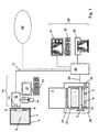
- Fig. 1 shows a system for processing an image carrier for x-ray information.
- the system comprises an identification station 10, which is also referred to below as ID station, a read-out device 20, a playback device 30 and a central memory 40th
- the image carrier for X-ray information consists of a cassette 2 with a therein
- the image plate 1 comprises a carrier layer with a Storage phosphor layer 5 applied thereto.
- the storage phosphor layer 5 preferably has a storage phosphor based on BaFBr: Eu or CsBr: Eu on.
- the image plate 1 is provided with an integrated circuit 3 having a Read-write memory includes in which data is written and from which Data can be read.
- the integrated circuit 3 preferably becomes at the back or - as in the example shown - in the edge region of the image plate 1 arranged.
- the integrated circuit 3 on the cassette 2 to be appropriate.
- the image plate 1 contained in the cassette 2 becomes in the storage phosphor layer 5 X-ray information is stored, for ID station 10 brought data to and from the integrated circuit 3 to read or write.
- the data transfer between the integrated Circuit 3 and the ID station 10 is preferably contactless. hereby can an exact positioning of the image plate 1 and the circuit 3rd relative to the ID station 10, as in a contact-based data transmission would be required.
- the contactless data transmission is preferably carried out by means of radio frequency waves (RF waves).
- RF waves radio frequency waves
- the ID station 10 a corresponding first read-write device 11 with a RF transmitter and an RF receiver on.
- the integrated circuit 3 is preferably in the form of a so-called RF label, which is also referred to as RF tag, attached to the image plate 1, glued, for example.
- RF tag includes besides the integrated one Circuit 3 an antenna designed as a transponder coil.
- the integrated circuit 3 in the form of a chip card in which an RF tag is inserted in a card-shaped plastic body at the Image plate 1 may be attached.
- the chip card is preferably detachable on the image plate 1 attached, e.g. by means of a simple plug connection in the edge area the image plate 1.
- a locking mechanism be provided, e.g. a snap mechanism in which the Chip card is locked by snapping.
- This attachment of the chip card the image plate 1 is both easy and safe and simplifies the other hand For example, in the case of a defect of the integrated circuit 3 required - Exchange of the chip card against another.
- the image plate 1 is provided with a mark 4 readable by the naked eye, which at least a part of the memory of the integrated circuit.
- 3 stored data, in particular for the optical disk 1 specific data represented and preferably formed as an alphanumeric string.
- This causes a defect of the integrated circuit 3, in which the data stored in it can generally no longer be read, the data contained in mark 4 remains accessible.
- the broken one integrated circuit 3 can be replaced in this case with a new one in which then the data contained in the mark 4 is written become.
- the data of the marking 4 are read by an operator, entered at the ID station 10 and finally in the new integrated circuit written. With the help of the marking 4 is thus ensured in a simple manner, that stored in the integrated circuit 3 and in the mark 3 contained part of the data even with a defect of the circuit 3 get lost.
- a mark 4 designed in this way can also be attached the cassette 2 may be attached.
- the procedure for a defect of the integrated Circuit is done in an analogous manner.
- the ID station 10 includes one or more input devices for input of data which, for example, for a patient to be examined, the Reading out the image plate 1 or the further processing of from the image plate. 1 read out image data is specific or required.
- the input devices comprise a keyboard 13 with display unit 12, such as As a monitor, and a card reader 15 for a card 14, on which there are data to enter.
- the card 14 a smart card, for example a health insurance card, on which patient-specific data, such as Name, address, date of birth and insurance number of a patient are stored.
- the card reader 15 reads this Data from the card 14 and passes them to a cache 16 the ID station 10. Also, the data entered via the keyboard 13 will be on pass the buffer 16.
- the display unit 12 may preferably be also act as a so-called. Touchscreen, in which displayed Functions and / or data by touching the corresponding areas of the Display can be selected.
- the input data is sent to the first one Read-write device 11 passed and integrated into the memory Circuit 3 written on the optical disk 1.
- the cassette 2 with the image plate 1 therein is the read-out device 20, where the cassette 2 is automatically opened, the image plate 1 is taken and fed into the interior of the read-out device 20.
- the image plate 1 is already completely out of the cassette pulled out and locked inside the read-out device 20.
- a scanner 21 which with a suitable transport mechanism 22 is moved in the transport direction T via the image plate 1, read.
- the scanner 21 is preferably designed as a so-called line scanner, which a line-shaped stimulation light source, preferably arranged in a row Laser diodes, and a line-shaped detector, preferably a linear one CCD array has.
- a line-shaped stimulation light source preferably arranged in a row Laser diodes
- a line-shaped detector preferably a linear one CCD array has.
- the scanner 21 may also be designed as a so-called flying spot scanner in which a single laser beam passes through a rotating polygon mirror is directed onto the storage phosphor layer 5, whereby these along individual Scanned lines point by point.
- the extinguishing device 23 comprises for this purpose a radiation source with a - compared to the stimulation light source - broadband spectrum and a suitable reflector for the reflection of erasing radiation on the storage phosphor layer 5 of the image plate 1.
- the read-out device 20 comprises a second read-write device 24, with which data read from or into the integrated circuit 3 or written can be.
- the second read-write device 24 preferably for contactless Data transmission, in particular by means of RF waves trained.
- the second read-write device 24 from the memory of the integrated Circuit 3 data read in particular to control the Reading out the image plate 1 with the scanner 21 and / or to control the deletion the image plate 1 with the extinguishing device 23 used.
- data can be integrated in the integrated circuit Circuit 3 are written to preferably data on the processing status the image plate 1 - for example, whether the image plate 1 already read or has been deleted - to update.
- image data which represent the X-ray information stored in the image plate 1.
- image data are transmitted via a first data bus 25, in particular a serial data bus, e.g. a so-called Fire Wire, to the central storage 40 transmitted and stored there.
- the image data stored in the central memory 40 may then be stored in the playback device 30 further processed and / or reproduced.
- the playback device 30 comprises a controllable by means of a keyboard 32 Monitor 31.
- a hard copy device 33 for example, a laser printer, provided for outputting the image data be.
- the central memory 40 can optionally be connected to a network 50, in particular to a local area network (LAN). This will enable that from other systems, especially from other ID stations and / or playback devices to the stored in the central memory 40 Data or image data can be accessed.
- LAN local area network
- the central memory 40 may be formed as a separate central unit, which e.g. can be integrated in a central file server. Alternatively, the Central memory 40 but also an integral part of the ID station 10, the read-out device 20 or the playback device 30 be.
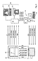
- Fig. 2 shows a first example of a structure of the memory M of the integrated Circuit 3 of the image carrier stored data. Based on this structure will below the data transmission within the system described in Fig. 1 explained in more detail. It should be noted that the representation chosen here is the Structure of the data reflects only highly schematized and not on a specific spatial arrangement or a particular order of data in memory M of the integrated circuit 3 is limited.
- the data stored in the memory M are in different data groups IPI, IPS, IPC, IPP, CAL and IDP summarized and there as each Filed ASCII string.
- Each data group is a version number VN as well assigned a checksum CS.
- the version number VN at the beginning of each data group indicates in which Data structure the data of a data group are stored. This will be the Possibility opens, different data structures of the same data group provided. This is always required if other or additional Data should be stored in the memory M, for example, a new one Image plate type or a new way of processing the image data.
- the version number VN of a data group can be the individual components of the system, e.g. the ID station 10, the read-out device 20 and the Playback device 30, recognize which data in the respective data group are contained and in which data length, sequence etc. these data are available.
- the check sum CS at the end of each data group is derived from the individual data in this data group. Based on the respective checksum CS can be determined whether the data of this data group have been stored or read without error.
- the content of the image carrier data group IPI is additionally applied to the image plate 1 and / or the cassette 2 as a visually readable marking 4 (see FIG. 1).
- This has the advantage that the data of the image carrier data group IPI specific to the image plate 1 or cassette 2 and required for its processing can not be lost even if the integrated circuit 3 is defective and can no longer be read out. In such a case, the defective integrated circuit 3 is simply replaced with a new integrated circuit, which is then described with the data taken from the tag 4.
- a mark 4 may be for example as follows: 301 - 6KBQMF0001 - 20030702 - 1 - 1 - 0 -1000 -1000 - 123
- the first three (301) and the last three (123) characters contain the version number VN or the checksum CS.
- the version number VN follow the Optical disk serial number (6KBQMF0001), the initialization date (20030702), Values for the image plate size (1), the size (1) of the surface to be read Image plate and the image plate type (0), the image plate sensitivity (1000) and finally, the optical disk erase feature (1000).
- the data taken from the marker 4 can be at the ID station 10 to simple Way written in the memory of the new integrated circuit without a new initialization at the manufacturer of the image plate 1 or Cassette 2 would be required.
- the data of the mark 4 read by an operator, entered via the keyboard 13 of the ID station 10 and then into the memory of the new integrated circuit written.
- readable mark 4 provides a particularly simple way of additional assurance of in the integrated circuit 3 stored data.
- a machine readable mark (not shown) may be provided, for example in Shape of a barcode or magnetic stripe. To enter the in the machine readable marking is then a corresponding barcode or magnetic stripe reader required, which is the machine-readable data to ID station 10, where it then enters the new integrated circuit can be written.
- a processing data group IPP data stored for one Further processing of obtained from the X-ray information of the image plate 1 Image data are required. This data is used exclusively by the playback device 30, which a corresponding image processor for further processing the image data includes, accessed. The readout process in the readout device 20 is not affected by this data.
- the playback device 30 can then easily both on the image data to be processed as well as the required for this Access data from the processing data group IPP.
- the calibration data of the image plate 1 are in the read-out device 20 to a Pre-evaluation of the obtained when reading the optical disk 1 by means of scanner 21 Image signals used to locally different sensitivities of the image plate 1 for X-ray radiation.
- the calibration data become this read in the read-out device 20 from the integrated circuit 3 and the preprocessing of the image signals supplied.
- the calibration data can already be obtained from the integrated station at the ID station 10 Circuit 3 read, via a second data bus 17 to the central memory 40 transferred and stored there.
- a readout and transfer the calibration data to the central memory 40 during the first read operation in the read-out device 20 can then be omitted.
- the second data bus 17 is also preferably a serial data bus, e.g. as RS-232 data bus, formed.
- calibration data of the image plate 1 are in the central memory 40 or in Memory of the read-out device 20 also stored calibration data of the scanner 21, which reflect local differences in the sensitivity of the scanner 21 and preferably together with the calibration data of the image plate 1 for Preprocessing of the image signals are used. From preprocessing The image signals are finally image data stored in the optical disk 1 Radiograph obtained from which the influence of locally different sensitivities the image plate 1 and the scanner 21 has been eliminated.
- the two-dimensional data field includes the calibration data of the image plate 1 between about 30 and 40 columns and between about 40 and 50 rows on, wherein the length of each data is two bytes.
- the calibration data gives the sensitivity of individual areas of the storage phosphor layer 5, which are greater than the individual pixels obtained by reading the image plate 1 line by line (Pixel). In this way, the space requirement for the calibration data in the integrated circuit 3 are greatly reduced, at the same time locally different Sensitivity can be considered with a high accuracy.
- the calibration data but also the sensitivity of the optical disk 1 in individual Play back areas of the image panel that correspond to each pixel. This allows a pixel-accurate calibration that varies locally Sensitivity taken into account with even higher accuracy.
- the calibration data of the optical disk 1 are advantageously subjected to a compression process before this in the integrated circuit 3 are stored.
- a reference code IDP-Ref in the Memory M written which is a reference to the data of the patient data group IDP stored in the central memory 40.
- the reference code IDP-Ref which is also referred to as patient identification code and a unique identification of the patient is possible with the first Read-write device 11 of the ID station 10 in the memory M of the integrated Circuit 3 and written together with the data of the patient data group IDP in the buffer 16 of the ID station 10 and / or in the central memory 40 saved.
- patient identification code IDP-Ref On the basis of the patient identification code IDP-Ref can then on the in the cache 16 or central memory 40 stored patient-specific Data is accessed.
- the patient identification code IDP-Ref becomes this either in the ID station 10 or in the read-out device 20 from the integrated Circuit 3 is read and transmitted to the playback device 30 or together with the image data read from the image plate 1 to the reproducing apparatus 30 transmitted, which then based on the patient identification code IDP-Ref to the appropriate patient-specific Data in the buffer 16 or central memory 40 can access.
- the patient data group IDP can also be omitted if in the Processing data group IPP - as already described above - already reference codes intended for patient data, which u.a. to the corresponding ones Patient data, such as Name and / or date of birth and / or gender of the patient, in the central memory 40.
- FIG. 3 shows a schematic representation of a first variant of the data flow between the individual components of the invention shown in Fig. 1 System. The data flow is subsequently based on a complete radiography procedure explained in more detail.
- the ID station 10 instead of the data of the control, processing and patient data group IPC, IPP or IDP one or more reference codes IPC-Ref, IPP-Ref or IDP-Ref in the memory M of the integrated circuit 3 of the image plate 1 or cassette 2 written.
- the reference codes IPC-Ref, IPP-Ref or IDP-Ref together with the corresponding data of the control, processing and and patient data group IPC, IPP or IDP in the central memory 40 saved.
- the reference codes IPC-Ref, IPP-Ref or IDP-Ref can then the read-out device 20 to the data stored in the central memory 40 of the data corresponding data group IPC, IPP or IDP.
- FIG. 4 shows a schematic representation of a second variant of the data flow between the individual components of the system shown in FIG.
- this variant of the data flow at the ID station 10-as above described in more detail - data of the state, control, processing and patient data group IPS, IPC, IPP or IDP entered, but not in the memory M of the integrated circuit 3 located on the optical disk 1, but transferred to the central memory 40 and stored there.
- the Memory M of the integrated circuit 3 are only data in this variant the image carrier and calibration data group IPI or CAL.
- Corresponding are in the read-out device 20 only data of thessenhariund Calibration data group IPI or CAL, which is disk-specific data or the calibration data of the image plate 1, from the integrated circuit 3 read.
- the mark is 4, which are part of the memory M of the integrated circuit 3 stored Represents data, in particular data of the image carrier data group IPI, mounted on the back of the carrier layer of the image plate 1.
- the mark 4 is therefore shown in dashed lines.
- FIG. 5 shows a second example of a structure of the integrated circuit 3 of FIG Image carrier stored data in the variant of the data flow shown in Fig. 4.
- IPI or CAL data of the image carrier and calibration data group IPI or CAL stored in the memory M.
Landscapes
- Health & Medical Sciences (AREA)
- Life Sciences & Earth Sciences (AREA)
- Physics & Mathematics (AREA)
- Engineering & Computer Science (AREA)
- General Physics & Mathematics (AREA)
- High Energy & Nuclear Physics (AREA)
- Medical Informatics (AREA)
- Molecular Biology (AREA)
- Heart & Thoracic Surgery (AREA)
- Animal Behavior & Ethology (AREA)
- Radiology & Medical Imaging (AREA)
- Biomedical Technology (AREA)
- Optics & Photonics (AREA)
- Nuclear Medicine, Radiotherapy & Molecular Imaging (AREA)
- Surgery (AREA)
- Pathology (AREA)
- General Health & Medical Sciences (AREA)
- Public Health (AREA)
- Veterinary Medicine (AREA)
- Biophysics (AREA)
- Spectroscopy & Molecular Physics (AREA)
- Apparatus For Radiation Diagnosis (AREA)
- Radiography Using Non-Light Waves (AREA)
- Image Analysis (AREA)
Abstract
Description
- Fig. 1
- ein System zur Bearbeitung eines Bildträgers für Röntgeninformation;
- Fig. 2
- ein erstes Beispiel einer Struktur der im integrierten Schaltkreis des Bildträgers gespeicherten Daten;
- Fig. 3
- eine schematische Darstellung einer ersten Variante des Datenflusses zwischen einzelnen Komponenten des in Fig. 1 dargestellten Systems;
- Fig. 4
- eine schematische Darstellung einer zweiten Variante des Datenflusses zwischen einzelnen Komponenten des in Fig. 1 dargestellten Systems; und
- Fig. 5
- ein zweites Beispiel einer Struktur der im integrierten Schaltkreis des Bildträgers gespeicherten Daten.
- Initialisierungsdatum: entspricht dem Datum, an welchem die Daten der Bildträger-Datengruppe IPI in den Speicher M der Bildplatte 1 geschrieben wurden;
- Bildplatten-Seriennummer: dient zur eindeutigen Identifizierung der Bildplatte 1 und ist vorzugsweise aus einem die jeweilige Produktcharge der Bildplatte 1 identifizierenden Code und einer laufenden Nummer zusammengesetzt;
- Bildplattengröße;
- Größe einer auszulesenden Fläche auf der Bildplatte 1;
- Bildplattentyp: z.B. Bildplatte auf der Basis von pulverförmigen oder nadelförmigen Speicherleuchtstoffen, wie z.B. sogenannte Powder-IP bzw. Needle-IP;
- Bildplatten-Empfindlichkeit;
- Bildplatten-Löscheigenschaft: z.B. als Maß für die Dauer und/oder Intensität des von einer Löscheinrichtung 23 abgegebenen Lichts.
- Bildplattenstatus: z.B. ob die Bildplatte 1 bereits initialisiert ist (d.h. Daten der Bildträger-Datengruppe IPI im Speicher M gespeichert sind) und/oder ein Röntgenbild bereits aufgenommen, gelöscht bzw. noch zu löschen ist;
- Bildplattenzyklen: Gesamtzahl von Röntgenaufnahmen mit dieser Bildplatte 1. Diese Gesamtzahl wird nach jedem Auslesevorgang oder Löschvorgang in der Auslesevorrichtung 20 um den Wert 1 erhöht;
- Auslesen unter Biegung: Anzahl der Bildplattenzyklen, in welchen die Bildplatte 1 während des Auslesevorgangs gekrümmt wird. Diese Zahl ist ein Maß für den Abnutzungs- und/oder Beschädigungsgrad einer Bildplatte 1. Dieser Eintrag kann beispielsweise bei Systemen entfallen, in welchen die Bildplatte während des Auslesens auf einer festen, ebenen Unterlage aufliegt und folglich nicht gebogen wird.
- Scannerempfindlichkeit: gibt die im Scanner 21 beim Auslesen der Bildplatte 1 einzustellende Empfindlichkeit an und ist abhängig von der Röntgendosis in Bereichen der Bildplatte 1, welche diagnostische Informationen enthalten;
- Röntgendosis: entspricht der maximalen Röntgendosis während einer Röntgenaufnahme und stellt ein Maß für die einzustellende Intensität der Löscheinrichtung 23 beim Löschen der Bildplatte 1 dar;
- Betriebsmodus: z.B. Weglassen oder Auslesen von Röntgeninformation aus bestimmten Randbereichen der Bildplatte 1.
- Referenzcode für die Art der durchzuführenden Weiterverarbeitung;
- Referenzcode für Aufnahme- und Patientendaten;
- Eindeutige Kennzeichnung des Zentralspeichers, auf welchen die Referenzcodes verweisen, wie z.B. der Name des Zentralspeichers in einem Netzwerk.
- Anzahl der Spalten des zweidimensionalen Datenfeldes der Kalibrierdaten;
- Anzahl der Zeilen des zweidimensionalen Datenfeldes der Kalibrierdaten;
- zweidimensionales Datenfeld der Kalibrierdaten.
- Name des Patienten;
- Geburtsdatum des Patienten;
- Geschlecht des Patienten.
Claims (28)
- Bildträger (1, 2) zur Speicherung von Röntgeninformation, gekennzeichnet durch einen elektronischen Speicher (M) zur Speicherung von Kalibrierdaten des Bildträgers (1, 2), welche ein Maß für die Empfindlichkeit des Bildträgers (1, 2) für Röntgenstrahlung darstellen und bei einer Verarbeitung von Bildsignalen, welche bei einem Auslesen der Röntgeninformation aus dem Bildträger (1, 2) erhalten werden, herangezogen werden können.
- Bildträger (1, 2) nach Anspruch 1, dadurch gekennzeichnet, dass die Kalibrierdaten des Bildträgers (1, 2) ein Maß für eine über eine Speicherleuchtstoff-Schicht (5) des Bildträgers (1, 2) lokal veränderliche Empfindlichkeit des Bildträgers (1, 2) für Röntgenstrahlung darstellen.
- Bildträger (1, 2) nach Anspruch 2, dadurch gekennzeichnet, dass die Kalibrierdaten des Bildträgers (1, 2) in einem zweidimensionalen Datenfeld im elektronischen Speicher (M) des Bildträgers (1, 2) gespeichert sind.
- Bildträger (1, 2) nach Anspruch 2 oder 3, dadurch gekennzeichnet, dass die Kalibrierdaten des Bildträgers (1, 2) die lokal veränderliche Empfindlichkeit des Bildträgers (1, 2) in einzelnen Bereichen des Bildträgers wiedergeben, wobei die einzelnen Bereiche den einzelnen Bildpunkten entsprechen, die bei einem Auslesen der im Bildträger (1, 2) gespeicherten Röntgeninformation erhalten werden.
- Bildträger (1, 2) nach Anspruch 2 oder 3, dadurch gekennzeichnet, dass die Kalibrierdaten des Bildträgers (1, 2) die lokal veränderliche Empfindlichkeit des Bildträgers (1, 2) in einzelnen Bereichen des Bildträgers wiedergeben, wobei die einzelnen Bereiche größer sind als die einzelnen Bildpunkte, die bei einem Auslesen der im Bildträger (1, 2) gespeicherten Röntgeninformation erhalten werden.
- Bildträger (1, 2) nach einem der vorangehenden Ansprüche, dadurch gekennzeichnet, dass die Kalibrierdaten des Bildträgers (1, 2) in einer Kalibrierungs-Datengruppe (CAL) im elektronischen Speicher (M) des Bildträgers (1, 2) gespeichert sind.
- Bildträger (1, 2) nach Anspruch 6, dadurch gekennzeichnet, dass die Kalibrierungs-Datengruppe (CAL) eine Versionsnummer (VN) umfasst, welche die Struktur, in welcher die Daten der Kalibrier-Datengruppe (CAL) vorliegen, kennzeichnet.
- Bildträger (1, 2) nach Anspruch 6 oder 7, dadurch gekennzeichnet, dass die Kalibrierungs-Datengruppe (CAL) eine aus den Daten der Kalibrierungs-Datengruppe (CAL) abgeleitete Prüfsumme (CS) umfasst, anhand welcher überprüft werden kann, ob die Daten der Kalibrierungs-Datengruppe (CAL) fehlerfrei gespeichert und/oder gelesen worden sind.
- Bildträger (1, 2) nach einem der vorangehenden Ansprüche, dadurch gekennzeichnet, dass der Bildträger (1, 2) eine Bildplatte (1) zur Speicherung der Röntgeninformation umfasst.
- Bildträger (1,2) nach Anspruch 9, dadurch gekennzeichnet, dass der elektronische Speicher (M) an der Bildplatte (1) angebracht ist.
- Bildträger (1, 2) nach einem der Ansprüche 9 oder 10, dadurch gekennzeichnet, dass die Bildplatte (1) eine Trägerschicht mit einer auf der Vorderseite der Trägerschicht befindlichen Speicherleuchtstoff-Schicht (5) umfasst.
- Bildträger (1, 2) nach Anspruch 11, dadurch gekennzeichnet, dass der elektronische Speicher (M) in einem Randbereich der Trägerschicht, insbesondere außerhalb der Speicherleuchtstoff-Schicht (5), und/oder an der der Vorderseite gegenüberliegenden Rückseite der Trägerschicht angebracht ist.
- Bildträger (1, 2) nach Anspruch 9, dadurch gekennzeichnet, dass der Bildträger (1, 2) eine Kassette (2) umfasst, welche die Bildplatte (1) aufnehmen kann.
- Bildträger (1, 2) nach Anspruch 13, dadurch gekennzeichnet, dass der elektronische Speicher (M) an der Kassette (2) angebracht ist.
- Bildträger (1, 2) nach einem der vorangehenden Ansprüche, dadurch gekennzeichnet, dass der elektronische Speicher (M) des Bildträgers (1, 2) zur kontaktlosen Übertragung von Daten von und zu mindestens einer Bearbeitungsvorrichtung (10, 20) ausgebildet ist.
- Bildträger (1, 2) nach Anspruch 15, dadurch gekennzeichnet, dass der elektronische Speicher (M) als RF-Etikett ausgebildet ist, das den elektronischen Speicher (M) und eine Antenne, insbesondere eine Transponderspule, umfasst.
- Bildträger (1, 2) nach Anspruch 15, dadurch gekennzeichnet, dass der elektronische Speicher (M) als Chipkarte ausgebildet ist, die einen Kartenkörper umfasst, in welchen der elektronische Speicher (M) und eine Antenne, insbesondere eine Transponderspule, eingebracht sind.
- Bildträger (1, 2) nach Anspruch 17, dadurch gekennzeichnet, dass die Chipkarte lösbar an der Bildplatte (1) bzw. Kassette (2) befestigt ist.
- Bildträger (1, 2) nach Anspruch 18, dadurch gekennzeichnet, dass die Chipkarte mittels einer Steckverbindung an der Bildplatte (1) bzw. Kassette (2) befestigt ist.
- Bildträger (1, 2) nach Anspruch 19, dadurch gekennzeichnet, dass die Steckverbindung einen Mechanismus, insbesondere einen Schnappmechanismus, zum Arretieren der Chipkarte in der Steckverbindung aufweist.
- System zur Bearbeitung eines Bildträgers (1, 2) zur Speicherung von Röntgeninformation mitdadurch gekennzeichnet, dassmindestens einem Bildträger (1, 2) undmindestens einer Vorrichtung (10, 20, 30) zur Bearbeitung des Bildträgers (1, 2) und/oder zur Weiterverarbeitung und/oder Wiedergabe der im Bildträger (1, 2) gespeicherten Röntgeninformation,
der Bildträger (1, 2) einen elektronischen Speicher (M) zur Speicherung von Kalibrierdaten des Bildträgers (1, 2) umfasst, welche ein Maß für die Empfindlichkeit des Bildträgers (1, 2) für Röntgenstrahlung darstellen und bei einer Verarbeitung von Bildsignalen, welche bei einem Auslesen der Röntgeninformation aus dem Bildträger (1, 2) erhalten werden, herangezogen werden können. - System nach Anspruch 21, dadurch gekennzeichnet, dass eine Vorrichtung als Auslesevorrichtung (20) ausgebildet ist, welchedie im Bildträger (1, 2) gespeicherte Röntgeninformation auslesen und dabei entsprechende Bildsignale erzeugen kann unddie erzeugten Bildsignale unter Heranziehung der im elektronischen Speicher (M) gespeicherten Kalibrierdaten des Bildträgers (1, 2) verarbeiten kann.
- System nach Anspruch 22, dadurch gekennzeichnet, dass die Auslesevorrichtung (20) die im elektronischen Speicher (M) gespeicherten Kalibrierdaten des Bildträgers (1, 2) lesen kann.
- System nach Anspruch 23, dadurch gekennzeichnet, dass die Auslesevorrichtung (20) die aus dem elektronischen Speicher (M) ausgelesenen Kalibrierdaten des Bildträgers (1, 2) in einem Speicher, insbesondere in einem Zentralspeicher (40) und/oder einem Speicher der Auslesevorrichtung (20), speichern kann.
- Verfahren zur Bearbeitung eines Bildträgers (1, 2) zur Speicherung von Röntgeninformation,
dadurch gekennzeichnet, dassder Bildträger (1, 2) einen elektronischen Speicher (M) zur Speicherung von Kalibrierdaten des Bildträgers (1, 2) umfasst, welche ein Maß für die Empfindlichkeit des Bildträgers (1, 2) für Röntgenstrahlung darstellen und bei einer Verarbeitung von Bildsignalen, welche bei einem Auslesen der Röntgeninformation aus dem Bildträger (1, 2) erhalten werden, herangezogen werden können, unddie Kalibrierdaten nach einem ersten Auslesen der Kalibrierdaten aus dem elektronischen Speicher (M) des Bildträgers (1, 2) in einem Speicher, insbesondere in einem Zentralspeicher (40) oder in einem Speicher einer Auslesevorrichtung (20), gespeichert werden. - Verfahren nach Anspruch 25, dadurch gekennzeichnet, dass das erste Auslesen der Kalibrierdaten des Bildträgers (1, 2) aus dem elektronischen Speicher (M) des Bildträgers (1, 2) in einer Auslesevorrichtung (20) erfolgt.
- Verfahren nach Anspruch 25 oder 26, dadurch gekennzeichnet, dass bei einer erneuten Bearbeitung desselben Bildträgers (1, 2) die bereits in dem Speicher, insbesondere im Zentralspeicher (40) bzw. im Speicher der Auslesevorrichtung (20), gespeicherten Kalibrierdaten dieses Bildträgers (1, 2) aus dem Speicher, insbesondere dem Zentralspeicher (40) bzw. dem Speicher der Auslesevorrichtung (20), gelesen werden.
- Bildträger (1, 2) nach einem der Ansprüche 1 bis 20, dadurch gekennzeichnet, dass die Kalibrierdaten im elektronischen Speicher (M) des Bildträgers (1, 2) in komprimierter Form gespeichert sind.
Priority Applications (4)
| Application Number | Priority Date | Filing Date | Title |
|---|---|---|---|
| DE50309960T DE50309960D1 (de) | 2003-12-17 | 2003-12-17 | Verfahren zur Bearbeitung eines Bildträgers zur Speicherung von Röntgeninformation |
| EP03104749A EP1544674B1 (de) | 2003-12-17 | 2003-12-17 | Verfahren zur Bearbeitung eines Bildträgers zur Speicherung von Röntgeninformation |
| AT03104749T ATE397763T1 (de) | 2003-12-17 | 2003-12-17 | Verfahren zur bearbeitung eines bildträgers zur speicherung von röntgeninformation |
| US11/010,658 US7427769B2 (en) | 2003-12-17 | 2004-12-09 | Image carrier for storing X-ray information, and a system and method for processing an image carrier |
Applications Claiming Priority (1)
| Application Number | Priority Date | Filing Date | Title |
|---|---|---|---|
| EP03104749A EP1544674B1 (de) | 2003-12-17 | 2003-12-17 | Verfahren zur Bearbeitung eines Bildträgers zur Speicherung von Röntgeninformation |
Publications (2)
| Publication Number | Publication Date |
|---|---|
| EP1544674A1 true EP1544674A1 (de) | 2005-06-22 |
| EP1544674B1 EP1544674B1 (de) | 2008-06-04 |
Family
ID=34486396
Family Applications (1)
| Application Number | Title | Priority Date | Filing Date |
|---|---|---|---|
| EP03104749A Expired - Lifetime EP1544674B1 (de) | 2003-12-17 | 2003-12-17 | Verfahren zur Bearbeitung eines Bildträgers zur Speicherung von Röntgeninformation |
Country Status (4)
| Country | Link |
|---|---|
| US (1) | US7427769B2 (de) |
| EP (1) | EP1544674B1 (de) |
| AT (1) | ATE397763T1 (de) |
| DE (1) | DE50309960D1 (de) |
Cited By (2)
| Publication number | Priority date | Publication date | Assignee | Title |
|---|---|---|---|---|
| US7427769B2 (en) | 2003-12-17 | 2008-09-23 | Afga-Gevaert Healthcare Gmbh | Image carrier for storing X-ray information, and a system and method for processing an image carrier |
| DE102011089446A1 (de) * | 2011-12-21 | 2013-06-27 | Siemens Aktiengesellschaft | Verfahren zum Betreiben eines Röntgensystems, Röntgendetektor und Röntgensystem |
Families Citing this family (7)
| Publication number | Priority date | Publication date | Assignee | Title |
|---|---|---|---|---|
| US7355195B2 (en) * | 2004-04-27 | 2008-04-08 | Agfa Healthcare | Method and apparatus for associating patient and exposure related data with a radiation image |
| US7822173B2 (en) * | 2006-01-16 | 2010-10-26 | Koninklijke Philips Electronics N.V. | Smart radiation detector module |
| US7429737B2 (en) * | 2006-11-09 | 2008-09-30 | Carestream Health, Inc. | Retrofit digital mammography detector |
| US7783008B2 (en) * | 2007-03-30 | 2010-08-24 | General Electric Company | Digital radiograph patient positioning system and method |
| US7519156B2 (en) * | 2007-05-23 | 2009-04-14 | General Electric Company | Method and apparatus for hot swapping portable detectors in x-ray systems |
| JP2010184025A (ja) * | 2009-02-12 | 2010-08-26 | Fujifilm Corp | 放射線画像撮影システム、電源装置、充電装置、および放射線画像撮影方法 |
| EP2527874B1 (de) * | 2011-05-26 | 2017-10-11 | Agfa HealthCare NV | System, Vorrichtung und Verfahren zum Auslesen von in einer Speicherleuchtstoffplatte gespeicherten Röntgeninformationen |
Citations (8)
| Publication number | Priority date | Publication date | Assignee | Title |
|---|---|---|---|---|
| US4320296A (en) * | 1979-07-11 | 1982-03-16 | Fuji Photo Film Co., Ltd. | Method of and apparatus for recording image processing data in radiation image recording system |
| US4498005A (en) * | 1981-11-14 | 1985-02-05 | Fuji Photo Film Co., Ltd. | Cassette having radiation image storage medium |
| US4739480A (en) * | 1981-10-26 | 1988-04-19 | Fuji Photo Film Co., Ltd. | Radiation image reproducing apparatus with image storage ID code for identifying exposure data file |
| EP0727696A1 (de) * | 1995-02-17 | 1996-08-21 | Agfa-Gevaert N.V. | System und Verfahren der Identifizierung zur Verwendung im Felde der digitalen Röntgenphotographie |
| EP1031854A1 (de) * | 1999-02-22 | 2000-08-30 | Fuji Photo Film Co., Ltd. | Elektrische Signalverarbeitungsverfahren für radiographicher Bilder von eines stimulierbaren Phosphorblatts |
| WO2002042794A2 (en) * | 2000-11-21 | 2002-05-30 | Digidex Ltd. | Image system using ionizing radiation and a storage phosphor |
| EP1251683A1 (de) * | 2001-04-17 | 2002-10-23 | Konica Corporation | Netzwerksystem für das Radiographieren von Strahlungsbildern |
| EP1391780A1 (de) * | 2002-08-16 | 2004-02-25 | Konica Corporation | Lesegerät für Radiographische Bildern |
Family Cites Families (15)
| Publication number | Priority date | Publication date | Assignee | Title |
|---|---|---|---|---|
| DE3731204A1 (de) * | 1987-09-17 | 1989-03-30 | Agfa Gevaert Ag | Roentgenaufnahmekassette fuer blattfoermiges aufnahmematerial und verfahren zu deren verwendung |
| US5260573A (en) * | 1990-11-21 | 1993-11-09 | Konica Corporation | Radiographical image reading apparatus |
| US6047257A (en) * | 1997-03-01 | 2000-04-04 | Agfa-Gevaert | Identification of medical images through speech recognition |
| US6271536B1 (en) * | 1997-10-08 | 2001-08-07 | Agfa-Gevaert | Radiographic image identification method |
| US6389156B1 (en) * | 1997-10-09 | 2002-05-14 | Konica Corporation | Method and apparatus for reading radiographic images |
| US6249226B1 (en) * | 1998-09-10 | 2001-06-19 | Xerox Corporation | Network printer document interface using electronic tags |
| US6350985B1 (en) * | 1999-04-26 | 2002-02-26 | Direct Radiography Corp. | Method for calculating gain correction factors in a digital imaging system |
| US20010017356A1 (en) * | 2000-02-29 | 2001-08-30 | Bruno Van Uffel | Photostimulable phosphor read-out apparatus |
| EP1136842A3 (de) * | 2000-03-15 | 2002-12-04 | Fuji Photo Film Co., Ltd. | Auslesevorrichtung von Strahlungsbildern |
| JP2002174879A (ja) * | 2000-09-18 | 2002-06-21 | Eastman Kodak Co | 無線周波数識別トランスポンダを有するシート媒体パッケージ |
| TW511340B (en) * | 2000-12-12 | 2002-11-21 | Elan Microelectronics Corp | Method and system for data loss detection and recovery in wireless communication |
| JP2004004588A (ja) * | 2002-03-22 | 2004-01-08 | Fuji Photo Film Co Ltd | 放射線変換パネルを用いた放射線画像情報読取装置および放射線変換パネルの感度補正方法 |
| US6934358B2 (en) * | 2003-07-31 | 2005-08-23 | Radiological Imaging Technology, Inc. | Radiographic imaging system and method |
| ATE413628T1 (de) * | 2003-12-17 | 2008-11-15 | Agfa Gevaert Healthcare Gmbh | Bildträger zur speicherung von röntgeninformation sowie system zur bearbeitung eines solchen bildträgers |
| EP1544674B1 (de) * | 2003-12-17 | 2008-06-04 | Agfa-Gevaert HealthCare GmbH | Verfahren zur Bearbeitung eines Bildträgers zur Speicherung von Röntgeninformation |
-
2003
- 2003-12-17 EP EP03104749A patent/EP1544674B1/de not_active Expired - Lifetime
- 2003-12-17 AT AT03104749T patent/ATE397763T1/de not_active IP Right Cessation
- 2003-12-17 DE DE50309960T patent/DE50309960D1/de not_active Expired - Lifetime
-
2004
- 2004-12-09 US US11/010,658 patent/US7427769B2/en not_active Expired - Lifetime
Patent Citations (8)
| Publication number | Priority date | Publication date | Assignee | Title |
|---|---|---|---|---|
| US4320296A (en) * | 1979-07-11 | 1982-03-16 | Fuji Photo Film Co., Ltd. | Method of and apparatus for recording image processing data in radiation image recording system |
| US4739480A (en) * | 1981-10-26 | 1988-04-19 | Fuji Photo Film Co., Ltd. | Radiation image reproducing apparatus with image storage ID code for identifying exposure data file |
| US4498005A (en) * | 1981-11-14 | 1985-02-05 | Fuji Photo Film Co., Ltd. | Cassette having radiation image storage medium |
| EP0727696A1 (de) * | 1995-02-17 | 1996-08-21 | Agfa-Gevaert N.V. | System und Verfahren der Identifizierung zur Verwendung im Felde der digitalen Röntgenphotographie |
| EP1031854A1 (de) * | 1999-02-22 | 2000-08-30 | Fuji Photo Film Co., Ltd. | Elektrische Signalverarbeitungsverfahren für radiographicher Bilder von eines stimulierbaren Phosphorblatts |
| WO2002042794A2 (en) * | 2000-11-21 | 2002-05-30 | Digidex Ltd. | Image system using ionizing radiation and a storage phosphor |
| EP1251683A1 (de) * | 2001-04-17 | 2002-10-23 | Konica Corporation | Netzwerksystem für das Radiographieren von Strahlungsbildern |
| EP1391780A1 (de) * | 2002-08-16 | 2004-02-25 | Konica Corporation | Lesegerät für Radiographische Bildern |
Cited By (2)
| Publication number | Priority date | Publication date | Assignee | Title |
|---|---|---|---|---|
| US7427769B2 (en) | 2003-12-17 | 2008-09-23 | Afga-Gevaert Healthcare Gmbh | Image carrier for storing X-ray information, and a system and method for processing an image carrier |
| DE102011089446A1 (de) * | 2011-12-21 | 2013-06-27 | Siemens Aktiengesellschaft | Verfahren zum Betreiben eines Röntgensystems, Röntgendetektor und Röntgensystem |
Also Published As
| Publication number | Publication date |
|---|---|
| DE50309960D1 (de) | 2008-07-17 |
| ATE397763T1 (de) | 2008-06-15 |
| US7427769B2 (en) | 2008-09-23 |
| US20050133745A1 (en) | 2005-06-23 |
| EP1544674B1 (de) | 2008-06-04 |
Similar Documents
| Publication | Publication Date | Title |
|---|---|---|
| DE69530752T2 (de) | System und Verfahren der Identifizierung zur Verwendung im Felde der digitalen Röntgenphotographie | |
| EP1544673B1 (de) | Bildträger zur Speicherung von Röntgeninformation sowie System zur Bearbeitung eines solchen Bildträgers | |
| DE69331623T2 (de) | Automatische Leitwegsuche von digitalen Röntgenbildern zum gewählten Ziel | |
| DE69224110T2 (de) | Verarbeitungsverfahren für Aufzeichnungssysteme von Strahlungsbildern | |
| DE69412385T2 (de) | Speicherleuchtschirmleser, der die Bestrahlungsdauer und Grösse der Leuchtschirme erkennt | |
| DE69419984T2 (de) | Echtzeit-Einstellung von Fensterbreite und Pegel in einer radiographischen Arbeitsstation | |
| DE3731204A1 (de) | Roentgenaufnahmekassette fuer blattfoermiges aufnahmematerial und verfahren zu deren verwendung | |
| EP1544674B1 (de) | Verfahren zur Bearbeitung eines Bildträgers zur Speicherung von Röntgeninformation | |
| DE3856230T2 (de) | Kassette, Vorrichtung und Wischverfahren für ein stimulierbares Phosphorblatt | |
| EP1544672B1 (de) | Bildträger zur Speicherung von Röntgeninformation sowie System und Verfahren zur Bearbeitung eines solchen Bildträgers | |
| US20050205813A1 (en) | Radiation image information recording and reading system | |
| EP0706280B1 (de) | Stimulierbare Phosphorfolie und Verfahren zum Testen einer digitalen Abtast-Vorrichtung für stimulierbare Phosphorfolien | |
| DE69118735T2 (de) | Verfahren zur Identifizierung eines Röntgenfilms mit Patientendaten | |
| US20140191852A1 (en) | Method and system for phosphor plate identification in computed radiography | |
| DE69307694T2 (de) | Verfahren und Vorrichtung zur Überwachung der wirklich aufgebrachteten Bestrahlung | |
| EP2290404B1 (de) | Verfahren und Vorrichtung zum Auslesen und Löschen von in Speicherleuchstoffschichten gespeicherten Röntgeninformationen | |
| EP1653481A1 (de) | Speicherleuchtstoffplatte zur Speicherung von Röntgeninformationen und entsprechende Vorrichtung zum Auslesen der Röntgeninformationen | |
| DE19962773A1 (de) | Vorrichtung zum Auslesen von in einer Speicherschicht abgespeicherten Informationen sowie Röntgenkassette und Röntgentisch | |
| EP3509493B2 (de) | System und verfahren zur bereitstellung von aufnahmeparametern | |
| DE69412388T2 (de) | Speicherleuchtschirmleser mit Nachweis der Fehlfunktion von Löschlampen | |
| DE19629299A1 (de) | Verfahren und Vorrichtung zum Aufnehmen einer Bildinformation | |
| DE19646607C1 (de) | Verfahren und Vorrichtung zum lagerichtigen Verarbeiten von Röntgenkassetten | |
| DE69500229T2 (de) | Verfahren zur Qualitätssicherung von digitalen Röntgenaufnahmen | |
| DE69408676T2 (de) | Verfahren zur quantitativen Abtastgeometrieprüfung in einem digitalen radiographischen Wiedergabesystem | |
| EP1256017B1 (de) | Vorrichtung und verfahren zum auslesen von in einer speicherschicht abgespeicherten informationen sowie röntgenkassette |
Legal Events
| Date | Code | Title | Description |
|---|---|---|---|
| PUAI | Public reference made under article 153(3) epc to a published international application that has entered the european phase |
Free format text: ORIGINAL CODE: 0009012 |
|
| AK | Designated contracting states |
Kind code of ref document: A1 Designated state(s): AT BE BG CH CY CZ DE DK EE ES FI FR GB GR HU IE IT LI LU MC NL PT RO SE SI SK TR |
|
| AX | Request for extension of the european patent |
Extension state: AL LT LV MK |
|
| RAP1 | Party data changed (applicant data changed or rights of an application transferred) |
Owner name: AGFA-GEVAERT HEALTHCARE GMBH |
|
| 17P | Request for examination filed |
Effective date: 20051222 |
|
| AKX | Designation fees paid |
Designated state(s): AT BE BG CH CY CZ DE DK EE ES FI FR GB GR HU IE IT LI LU MC NL PT RO SE SI SK TR |
|
| 17Q | First examination report despatched |
Effective date: 20060124 |
|
| RTI1 | Title (correction) |
Free format text: METHOD OF PROCESSING A RADIATION IMAGE STORAGE MEDIUM |
|
| GRAP | Despatch of communication of intention to grant a patent |
Free format text: ORIGINAL CODE: EPIDOSNIGR1 |
|
| GRAS | Grant fee paid |
Free format text: ORIGINAL CODE: EPIDOSNIGR3 |
|
| GRAA | (expected) grant |
Free format text: ORIGINAL CODE: 0009210 |
|
| AK | Designated contracting states |
Kind code of ref document: B1 Designated state(s): AT BE BG CH CY CZ DE DK EE ES FI FR GB GR HU IE IT LI LU MC NL PT RO SE SI SK TR |
|
| REG | Reference to a national code |
Ref country code: GB Ref legal event code: FG4D Free format text: NOT ENGLISH |
|
| REG | Reference to a national code |
Ref country code: CH Ref legal event code: EP |
|
| REF | Corresponds to: |
Ref document number: 50309960 Country of ref document: DE Date of ref document: 20080717 Kind code of ref document: P |
|
| REG | Reference to a national code |
Ref country code: IE Ref legal event code: FG4D Free format text: LANGUAGE OF EP DOCUMENT: GERMAN |
|
| PG25 | Lapsed in a contracting state [announced via postgrant information from national office to epo] |
Ref country code: SI Free format text: LAPSE BECAUSE OF FAILURE TO SUBMIT A TRANSLATION OF THE DESCRIPTION OR TO PAY THE FEE WITHIN THE PRESCRIBED TIME-LIMIT Effective date: 20080604 Ref country code: ES Free format text: LAPSE BECAUSE OF FAILURE TO SUBMIT A TRANSLATION OF THE DESCRIPTION OR TO PAY THE FEE WITHIN THE PRESCRIBED TIME-LIMIT Effective date: 20080915 Ref country code: FI Free format text: LAPSE BECAUSE OF FAILURE TO SUBMIT A TRANSLATION OF THE DESCRIPTION OR TO PAY THE FEE WITHIN THE PRESCRIBED TIME-LIMIT Effective date: 20080604 |
|
| PG25 | Lapsed in a contracting state [announced via postgrant information from national office to epo] |
Ref country code: NL Free format text: LAPSE BECAUSE OF FAILURE TO SUBMIT A TRANSLATION OF THE DESCRIPTION OR TO PAY THE FEE WITHIN THE PRESCRIBED TIME-LIMIT Effective date: 20080604 |
|
| NLV1 | Nl: lapsed or annulled due to failure to fulfill the requirements of art. 29p and 29m of the patents act | ||
| REG | Reference to a national code |
Ref country code: IE Ref legal event code: FD4D |
|
| PG25 | Lapsed in a contracting state [announced via postgrant information from national office to epo] |
Ref country code: CZ Free format text: LAPSE BECAUSE OF FAILURE TO SUBMIT A TRANSLATION OF THE DESCRIPTION OR TO PAY THE FEE WITHIN THE PRESCRIBED TIME-LIMIT Effective date: 20080604 Ref country code: PT Free format text: LAPSE BECAUSE OF FAILURE TO SUBMIT A TRANSLATION OF THE DESCRIPTION OR TO PAY THE FEE WITHIN THE PRESCRIBED TIME-LIMIT Effective date: 20081104 Ref country code: IE Free format text: LAPSE BECAUSE OF FAILURE TO SUBMIT A TRANSLATION OF THE DESCRIPTION OR TO PAY THE FEE WITHIN THE PRESCRIBED TIME-LIMIT Effective date: 20080604 Ref country code: SE Free format text: LAPSE BECAUSE OF FAILURE TO SUBMIT A TRANSLATION OF THE DESCRIPTION OR TO PAY THE FEE WITHIN THE PRESCRIBED TIME-LIMIT Effective date: 20080904 |
|
| PG25 | Lapsed in a contracting state [announced via postgrant information from national office to epo] |
Ref country code: RO Free format text: LAPSE BECAUSE OF FAILURE TO SUBMIT A TRANSLATION OF THE DESCRIPTION OR TO PAY THE FEE WITHIN THE PRESCRIBED TIME-LIMIT Effective date: 20080604 Ref country code: SK Free format text: LAPSE BECAUSE OF FAILURE TO SUBMIT A TRANSLATION OF THE DESCRIPTION OR TO PAY THE FEE WITHIN THE PRESCRIBED TIME-LIMIT Effective date: 20080604 |
|
| RAP2 | Party data changed (patent owner data changed or rights of a patent transferred) |
Owner name: AGFA-GEVAERT HEALTHCARE GMBH |
|
| PLBE | No opposition filed within time limit |
Free format text: ORIGINAL CODE: 0009261 |
|
| STAA | Information on the status of an ep patent application or granted ep patent |
Free format text: STATUS: NO OPPOSITION FILED WITHIN TIME LIMIT |
|
| PG25 | Lapsed in a contracting state [announced via postgrant information from national office to epo] |
Ref country code: BG Free format text: LAPSE BECAUSE OF FAILURE TO SUBMIT A TRANSLATION OF THE DESCRIPTION OR TO PAY THE FEE WITHIN THE PRESCRIBED TIME-LIMIT Effective date: 20080904 Ref country code: EE Free format text: LAPSE BECAUSE OF FAILURE TO SUBMIT A TRANSLATION OF THE DESCRIPTION OR TO PAY THE FEE WITHIN THE PRESCRIBED TIME-LIMIT Effective date: 20080604 Ref country code: DK Free format text: LAPSE BECAUSE OF FAILURE TO SUBMIT A TRANSLATION OF THE DESCRIPTION OR TO PAY THE FEE WITHIN THE PRESCRIBED TIME-LIMIT Effective date: 20080604 |
|
| 26N | No opposition filed |
Effective date: 20090305 |
|
| BERE | Be: lapsed |
Owner name: AGFA-GEVAERT HEALTHCARE G.M.B.H. Effective date: 20081231 |
|
| PG25 | Lapsed in a contracting state [announced via postgrant information from national office to epo] |
Ref country code: MC Free format text: LAPSE BECAUSE OF NON-PAYMENT OF DUE FEES Effective date: 20081231 |
|
| REG | Reference to a national code |
Ref country code: CH Ref legal event code: PL |
|
| PG25 | Lapsed in a contracting state [announced via postgrant information from national office to epo] |
Ref country code: IT Free format text: LAPSE BECAUSE OF FAILURE TO SUBMIT A TRANSLATION OF THE DESCRIPTION OR TO PAY THE FEE WITHIN THE PRESCRIBED TIME-LIMIT Effective date: 20080604 |
|
| PG25 | Lapsed in a contracting state [announced via postgrant information from national office to epo] |
Ref country code: BE Free format text: LAPSE BECAUSE OF NON-PAYMENT OF DUE FEES Effective date: 20081231 |
|
| PG25 | Lapsed in a contracting state [announced via postgrant information from national office to epo] |
Ref country code: LI Free format text: LAPSE BECAUSE OF NON-PAYMENT OF DUE FEES Effective date: 20081231 Ref country code: CH Free format text: LAPSE BECAUSE OF NON-PAYMENT OF DUE FEES Effective date: 20081231 |
|
| REG | Reference to a national code |
Ref country code: FR Ref legal event code: CA |
|
| PG25 | Lapsed in a contracting state [announced via postgrant information from national office to epo] |
Ref country code: AT Free format text: LAPSE BECAUSE OF NON-PAYMENT OF DUE FEES Effective date: 20081217 |
|
| PG25 | Lapsed in a contracting state [announced via postgrant information from national office to epo] |
Ref country code: CY Free format text: LAPSE BECAUSE OF FAILURE TO SUBMIT A TRANSLATION OF THE DESCRIPTION OR TO PAY THE FEE WITHIN THE PRESCRIBED TIME-LIMIT Effective date: 20080604 Ref country code: LU Free format text: LAPSE BECAUSE OF NON-PAYMENT OF DUE FEES Effective date: 20081217 Ref country code: HU Free format text: LAPSE BECAUSE OF FAILURE TO SUBMIT A TRANSLATION OF THE DESCRIPTION OR TO PAY THE FEE WITHIN THE PRESCRIBED TIME-LIMIT Effective date: 20081205 |
|
| PG25 | Lapsed in a contracting state [announced via postgrant information from national office to epo] |
Ref country code: TR Free format text: LAPSE BECAUSE OF FAILURE TO SUBMIT A TRANSLATION OF THE DESCRIPTION OR TO PAY THE FEE WITHIN THE PRESCRIBED TIME-LIMIT Effective date: 20080604 |
|
| PG25 | Lapsed in a contracting state [announced via postgrant information from national office to epo] |
Ref country code: GR Free format text: LAPSE BECAUSE OF FAILURE TO SUBMIT A TRANSLATION OF THE DESCRIPTION OR TO PAY THE FEE WITHIN THE PRESCRIBED TIME-LIMIT Effective date: 20080905 |
|
| REG | Reference to a national code |
Ref country code: FR Ref legal event code: PLFP Year of fee payment: 13 |
|
| REG | Reference to a national code |
Ref country code: FR Ref legal event code: PLFP Year of fee payment: 14 |
|
| REG | Reference to a national code |
Ref country code: GB Ref legal event code: 732E Free format text: REGISTERED BETWEEN 20170824 AND 20170830 |
|
| REG | Reference to a national code |
Ref country code: FR Ref legal event code: PLFP Year of fee payment: 15 |
|
| REG | Reference to a national code |
Ref country code: FR Ref legal event code: TP Owner name: AGFA HEALTHCARE NV, BE Effective date: 20171114 |
|
| REG | Reference to a national code |
Ref country code: GB Ref legal event code: 732E Free format text: REGISTERED BETWEEN 20180816 AND 20180822 |
|
| REG | Reference to a national code |
Ref country code: DE Ref legal event code: R081 Ref document number: 50309960 Country of ref document: DE Owner name: AGFA NV, BE Free format text: FORMER OWNER: AGFA-GEVAERT HEALTHCARE GMBH, 50829 KOELN, DE |
|
| PGFP | Annual fee paid to national office [announced via postgrant information from national office to epo] |
Ref country code: DE Payment date: 20191030 Year of fee payment: 17 |
|
| PGFP | Annual fee paid to national office [announced via postgrant information from national office to epo] |
Ref country code: FR Payment date: 20191030 Year of fee payment: 17 |
|
| PGFP | Annual fee paid to national office [announced via postgrant information from national office to epo] |
Ref country code: GB Payment date: 20191030 Year of fee payment: 17 |
|
| REG | Reference to a national code |
Ref country code: DE Ref legal event code: R119 Ref document number: 50309960 Country of ref document: DE |
|
| GBPC | Gb: european patent ceased through non-payment of renewal fee |
Effective date: 20201217 |
|
| PG25 | Lapsed in a contracting state [announced via postgrant information from national office to epo] |
Ref country code: FR Free format text: LAPSE BECAUSE OF NON-PAYMENT OF DUE FEES Effective date: 20201231 |
|
| PG25 | Lapsed in a contracting state [announced via postgrant information from national office to epo] |
Ref country code: GB Free format text: LAPSE BECAUSE OF NON-PAYMENT OF DUE FEES Effective date: 20201217 Ref country code: DE Free format text: LAPSE BECAUSE OF NON-PAYMENT OF DUE FEES Effective date: 20210701 |