EP1544628B1 - Anschlussvorrichtung für einen Stromzähler - Google Patents
Anschlussvorrichtung für einen Stromzähler Download PDFInfo
- Publication number
- EP1544628B1 EP1544628B1 EP04028540A EP04028540A EP1544628B1 EP 1544628 B1 EP1544628 B1 EP 1544628B1 EP 04028540 A EP04028540 A EP 04028540A EP 04028540 A EP04028540 A EP 04028540A EP 1544628 B1 EP1544628 B1 EP 1544628B1
- Authority
- EP
- European Patent Office
- Prior art keywords
- channel
- connection
- section
- connection apparatus
- electricity meter
- Prior art date
- Legal status (The legal status is an assumption and is not a legal conclusion. Google has not performed a legal analysis and makes no representation as to the accuracy of the status listed.)
- Expired - Lifetime
Links
- 230000005611 electricity Effects 0.000 title claims abstract description 40
- 239000004020 conductor Substances 0.000 description 5
- 238000006073 displacement reaction Methods 0.000 description 4
- RYGMFSIKBFXOCR-UHFFFAOYSA-N Copper Chemical compound [Cu] RYGMFSIKBFXOCR-UHFFFAOYSA-N 0.000 description 2
- 229910052802 copper Inorganic materials 0.000 description 2
- 239000010949 copper Substances 0.000 description 2
- 239000000463 material Substances 0.000 description 2
- 239000002184 metal Substances 0.000 description 2
- 229910052751 metal Inorganic materials 0.000 description 2
- 230000015572 biosynthetic process Effects 0.000 description 1
- 150000001875 compounds Chemical class 0.000 description 1
- 231100001261 hazardous Toxicity 0.000 description 1
- 238000009434 installation Methods 0.000 description 1
- 238000002955 isolation Methods 0.000 description 1
- 230000007935 neutral effect Effects 0.000 description 1
- 230000002093 peripheral effect Effects 0.000 description 1
- 239000007787 solid Substances 0.000 description 1
Images


Classifications
-
- G—PHYSICS
- G01—MEASURING; TESTING
- G01R—MEASURING ELECTRIC VARIABLES; MEASURING MAGNETIC VARIABLES
- G01R22/00—Arrangements for measuring time integral of electric power or current, e.g. electricity meters
- G01R22/06—Arrangements for measuring time integral of electric power or current, e.g. electricity meters by electronic methods
- G01R22/061—Details of electronic electricity meters
- G01R22/065—Details of electronic electricity meters related to mechanical aspects
Definitions
- the invention relates to a connection device for an electricity meter or an electricity meter and a connection device for the electricity meter, with a power meter receiving the support plate and extending on the connection side parallel to the plate plane channel for laying on the electricity meter to be connected lines.
- Newer electricity meters especially electronic counters, such as those from the DE 100 52 998 A1 and DE 100 54 770 A1 emerge, in addition to the counter housing protruding contact pieces for connecting phase conductors and possibly the neutral conductor further connections for low voltage signal lines leading, control lines and / or supply lines. For example, remote queries can be made via such lines.
- connection plate which allows the connection of a single-phase electricity meter on a connection device for a three-phase electricity meter.
- the connection plate is placed on the connecting device for three-phase electricity meters and laid behind her according to the lines.
- a channel for the installation of the control or signal lines is provided in the plate. The channel space is separated from the rest of the space below the plate by a strut.
- the US 5,853,300 describes a connection device for electricity meters, in which in addition to the phase conductors auxiliary lines such as signal lines between the ammeter and the connection device can be performed to the ammeter. These lines are led from the back of the ammeter on the outer plate of the connection device between the slots for the contacts of the electricity meter and through slots in the socket of the connecting device to the outside.
- the present invention has for its object to provide a new connection device for an electricity meter of the type mentioned above, which allows a convenient and secure connection of such additional signal lines to the electricity meter.
- connection device solving this problem is characterized in that the channel is formed as an elongated recess in the support plate and / or the electricity meter, open to the connection side of the support plate or to the support plate and covered by the connected electricity meter or the support plate is.
- Such a channel according to the invention allows an orderly laying of signal lines to terminals on the electricity meter, which are facing the support plate and covered and protected by the electricity meter itself.
- the channel is open to the connection side of the support plate or to the support plate and the channel covered by the connected electricity meter or the support plate.
- lines can be laid after the connection device is installed. The cover prevents manipulation of the cables.
- the signal lines may leak out of the one-sided open channel, and there is enough mounting clearance and agility depending on the channel length to conveniently disengage the signal lines from the counter.
- the wires can be connected easily during meter mounting.
- the channel is widened in a portion opposite the terminals of the leads at the electrical meter to provide clearance for the routing of the leads in a loop.
- Connections formed on the counter may protrude into this clearance or be recessed from the counter facing surface of the support plate. The widening allows a gentle kink-free laying of the signal lines in the connection area.
- an opening may be provided in the support plate and the lead loop then extend into a cavity formed behind the plate.
- the channel extends along a side edge of the support plate near the side edge. Accordingly, connections are formed at the bottom edge of the meter, which are easily accessible and allow convenient connection of the lines to the meter.
- connection device forms an adapter which can be connected to the meter cross of a conventional meter slot for the electricity meter, in particular for an electronic electricity meter.
- connection device or such adapter may have a portion in the form of a flat box and a portion in the form of a terminal block, wherein the terminal block portion may have a channel extending portion which extends for example at an angle to the channel at the box portion.
- the Signal lines can be so oblique to the side of the phase conductors separately or supply.
- a step may be formed.
- the channel extends from the junction of the lines at the counter down or up. It can also be a down and an upwardly leading channel formed.
- the channel and the extension portion are formed on a one-piece, the box portion and the terminal block portion occlusive cover.
- the connecting device according to the invention can be used advantageously in particular for a power meter having a housing, projecting from its against a support plate engageable bottom through openings in the support plate passable contact elements corresponding to at least one phase, which with stromzu- and -abveden connection elements on the Electricity meter side facing away from the support plate are connected.
- this compound can be done by moving the guided on the support plate housing on the support plate.
- the connecting elements can be bridged by a displaceably guided in the direction of displacement of the electricity meter part and the bridging part when connecting the electricity meter by at least one of the contact elements from a bridging position to be displaced into an open position.
- an outlet opening of a channel extending upwards from the connection point of the lines to the meter or, if required, can be produced.
- a part of the relevant wall of the box section is breakable to form the opening.
- the channel may have an ausbrechid or ausschneidbare if necessary cover. If there is no need to connect lines to the meter, the channel can remain closed.
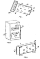
- a part of a connection device or an adapter produced in one piece from plastic material and shown in FIG. 1 has a section 1 in the form of a flat box and a section 2 in the form of a connection strip. From the bottom of the box section 1 extending into the terminal block section extending into ridges 3 to 9, which serve the mutual isolation of Anschlußleitem for three phases of current.
- An opening 10 in the bottom of the box section 1 and slot-like edge cutouts 11 and 12 at the terminal block section 2 are used to attach the adapter to the counter cross of a conventional counter space.
- each of the three current phases are between two of the above insulating ribs 3 to 9 two connecting elements 13 and 14 in the form of solid, pre-bent Copper sheet strips arranged and led to terminal block section 2.
- Each of the connecting elements 13 and 14 is assigned to the box section 1 spring member 15 and 16 respectively, each having a pair of opposing spring legs, between which the respective connection element is clamped.
- Each of the three pairs of connection elements 13 and 14 is assigned a bridging part 17 in the form of an angled piece of sheet metal made of copper. In FIG. 1, for the sake of clarity, only one of these bridging parts is shown.
- Each of the three bridging parts 17 has an edge recess 18.
- one of the plate 19 protruding insulating piece 20 engages in the peripheral recess 18.
- Each of the integrally connected with the plastic plate 19 insulating pieces 20 in turn has a recess 21 which is aligned with a slot opening 22 in the plate 19.
- the recess 21 is slightly widened towards the slot opening 22, as is apparent from Fig. 2.
- web projections 23 serve as a stop for the respective bridging member 17.
- the plate 19 has further corresponding to the corners of a triangle arranged slot openings 22 'and a slot opening 25.
- a cover 26 shown in FIGS. 3 and 4 with a plate section 27 and a terminal strip section 28 can be placed to complete the adapter.
- the plate portion 27 has the slot openings 22,22 'and 25 in the plate 19 correspondingly arranged slot openings 29 which are longer than the respective slot openings in the plate 19.
- a hollow opening 30, open at the front, on the rear side of the plate section 27 has an opening 31 which is congruent with the opening 10 in the bottom of the box section 1.
- a forwardly open channel 32 for the laying of signal lines 42 (Fig. 7) to an electronic power meter, as shown in Fig. 5 and 6 is shown.
- a continuous slot opening 33 in the plate section 27 aligned with the channel 32 makes room for the formation of conductor loops of the signal lines near the connection point on the electricity meter.
- the channel 32 extending along the side edge of the plate portion 27 continues on the terminal block portion 28.
- a step 40 is formed between the channel 32 and an extension portion 32 '.
- the extension portion 32 ' is at an angle to the channel 32.
- the extension portion 32' is closed by a required for the terminal block part 2, sealable cover.
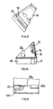
- the electricity meter 34 shown in FIGS. 5 and 6 has a plastic housing 35 with a bottom part 36. From the insulating plastic material of the bottom part, a total of seven contact elements 37 in the form of sheet metal strips emerge.
- two hook elements 38 are respectively arranged, which are provided for engagement in slot openings 39 on the box section 1 of the adapter part shown in Fig. 1.
- connection socket is formed for signal lines laid in the channel 32, 32 '.
- the counter When connecting the electricity meter 34 to the adapter, the counter is placed on the support plate for the counter-forming plate portion 27 of the cover 26.
- the hook elements 38 thereby pass into the slot openings 39 on the box section 1 of the adapter part of FIG. 1 and the contact elements 37 pass through the seven slots 29 in the plate section 27 and then through the slots 22, 22 'and 25 in the plate 19 into the box section 1 in, wherein three of the contact elements 37 pass into the recesses 21 of the insulating pieces 20 on the plate 19, wherein the insulating pieces 20 comprise the respective contact element like a frame.
- the thickness of the contact element and the frame thickness are the same. Said widening of the recesses 21 facilitates the introduction of the respective contact elements.
- connection elements 14 and 15 are still bridged by the respective bridging member 17.
- the contact elements 37 are electrically separated from the respective bridging elements by the insulating pieces 20. At the contact elements 37 is not the installer hazardous voltage.
- the hook members 38 engage behind the respective end edge of the slot openings 39, and the electricity meter 34 is locked on the plate portion 27 against lifting in the plate portion 27 perpendicular direction.
- the bridging parts moved by the engaging contact elements and / or one of the web projections reach at one end out of contact with the relevant connection element and one broad side of the flat contact elements 37 abuts against the connection element or 15.
- the spring legs of the spring parts 15 and 16 respectively press the contact elements against the connection elements.
- the meter is in the operating position. By a sealable locking, not shown, this operating position can be fixed.
- a widening is formed through the slot opening 33 in relation to the connection socket 41 provided on the electricity meter 34 in such a way that signal lines 42 routed in the channel 32 can be brought to the counter 34 in a loop.
- the lines exit from the channel open to the counter 32, and there is sufficient mounting space and mobility for connecting or disconnecting the lines 42 given.
- the loop can expand into the mounting space inside.
- FIGS. 9 to 11 differs from the embodiment described above in that, in addition to a channel 32a leading from below to a slot opening 33a, starting from the slot opening 33a, a further channel 45 defined by a web 44 is formed to the top of a box section 1 a runs.
- an upper side wall 46 of the box part 1 a can be an opening for the passage from the connecting device upwardly emerging lines 42 a form. To form the opening, a portion 47 may be broken out of the side wall 46.
- the channel 45 is covered by a plate portion 27a (Fig. 10). With the meter connected, when a portion of the plate portion 27a covering the channel 45 is exposed, there is no access to the leads 42a.
- the channel 45 is formed in addition to the channel 32a. Deviating from this, only the channel 45 could be present.
Landscapes
- Engineering & Computer Science (AREA)
- Power Engineering (AREA)
- Physics & Mathematics (AREA)
- General Physics & Mathematics (AREA)
- Connections Arranged To Contact A Plurality Of Conductors (AREA)
- Electrophonic Musical Instruments (AREA)
- Measuring Pulse, Heart Rate, Blood Pressure Or Blood Flow (AREA)
- Arrangements For Transmission Of Measured Signals (AREA)
- Cable Accessories (AREA)
Description
- Die Erfindung betrifft eine Anschlussvorrichtung für einen Stromzähler oder einen Stromzähler und eine Anschlussvorrichtung für den Stromzähler, mit einer den Stromzähler aufnehmenden Tragplatte und einem auf der Anschlussseite parallel zur Plattenebene verlaufenden Kanal für die Verlegung an den Stromzähler anzuschließender Leitungen.
- Neuere Stromzähler, insbesondere elektronische Zähler, wie sie z.B. aus der
DE 100 52 998 A1 undDE 100 54 770 A1 hervorgehen, weisen neben vom Zählergehäuse vorstehenden Kontaktstücken zum Anschluss von Phasenleitern und ggf. des Nullleiters weitere Anschlüsse für Niederspannung führende Signalleitungen, Steuerleitungen oder/und Versorgungsleitungen auf. Über solche Leitungen können z.B. Fernabfragen erfolgen. - Aus der
FR 277 658 - Die
US 5 853 300 beschreibt eine Anschlussvorrichtung für Stromzähler, bei der zusätzlich zu den Phasenleitern Hilfsleitungen wie z.B. Signalleitungen zwischen dem Strommessgerät und der Anschlussvorrichtung zum Strommessgerät geführt werden können. Diese Leitungen werden von der Rückseite des Strommessgerätes aus auf der Außenplatte der Anschlussvorrichtung zwischen den Steckplätzen für die Kontakte des Stromzählers und durch Schlitze in der Fassung der Anschlussvorrichtung nach außen geführt. - Der vorliegenden Erfindung liegt die Aufgabe zugrunde, eine neue Anschlussvorrichtung für einen Stromzähler der eingangs erwähnten Art zu schaffen, welche einen bequemen und sicheren Anschluss solcher zusätzlichen Signalleitungen an den Stromzähler ermöglicht.
- Die diese Aufgabe lösende Anschlussvorrichtung nach der Erfindung ist dadurch gekennzeichnet, dass der Kanal als eine längliche Vertiefung in der Tragplatte oder/und dem Stromzähler gebildet ist, zur Anschlussseite der Tragplatte bzw. zur Tragplatte hin offen und durch den angeschlossenen Stromzähler bzw. die Tragplatte abgedeckt ist.
- Ein solcher Kanal nach der Erfindung erlaubt eine geordnete Verlegung von Signalleitungen zu Anschlüssen am Stromzähler, welche der Tragplatte zugewandt und durch den Stromzähler selbst abgedeckt und geschützt sind.
- Während es möglich wäre, den Kanal auf der Rückseite der Tragplatte vorzusehen, ist in einer bevorzugten Ausführungsform der Erfindung der Kanal zur Anschlussseite der Tragplatte bzw. zur Tragplatte hin offen und der Kanal durch den angeschlossenen Stromzähler bzw. die Tragplatte abgedeckt. Vorteilhaft lassen sich dann Leitungen verlegen, nachdem die Anschlussvorrichtung installiert ist. Die Abdeckung verhindert Manipulationen an den Leitungen. Wenn der Zähler zur Demontage von der Tragplatte abgenommen wird, können die Signalleitungen aus dem einseitig offenen Kanal austreten, und es besteht je nach Kanallänge genügend Montagefreiraum und Beweglichkeit, um die Signalleitungen vom Zähler bequem zu lösen. Umgekehrt können die Leitungen bei der Zählermontage mühelos angeschlossen werden.
- In der bevorzugten Ausführungsform der Erfindung ist der Kanal in einem den Anschlüssen der Leitungen am Stromzähler gegenüberliegenden Abschnitt aufgeweitet, um Freiraum für die Verlegung der Leitungen in einer Schleife zu bilden. Am Zähler gebildete Anschlüsse können in diesen Freiraum hinein vorstehen oder von der dem Zähler zugewandten Oberfläche der Tragplatte zurückversetzt sein. Die Aufweitung erlaubt eine schonende knickfreie Verlegung der Signalleitungen im Anschlussbereich.
- Zur Bildung des Freiraums kann eine Öffnung in der Tragplatte vorgesehen sein und die Leitungsschleife sich dann in einem hinter der Platte gebildeten Hohlraum hinein erstrecken.
- Zweckmäßig verläuft der Kanal entlang einem Seitenrand der Tragplatte nahe dem Seitenrand. Entsprechend sind Anschlüsse am Bodenrand des Zählers gebildet, welche leicht zugänglich sind und einen bequemen Anschluss der Leitungen am Zähler ermöglichen.
- In einer Ausführungsform der Erfindung bildet die Anschlussvorrichtung einen am Zählerkreuz eines herkömmlichen Zählerplatzes anschließbaren Adapter für den Stromzähler, insbesondere für einen elektronischen Stromzähler.
- Eine solche Anschlussvorrichtung bzw. solcher Adapter kann einen Abschnitt in Form eines flachen Kastens und einen Abschnitt in der Form einer Anschlussleiste aufweisen, wobei der Anschlussleistenabschnitt einen den Kanal verlängernden Abschnitt aufweisen kann, der z.B. im Winkel zu dem Kanal am Kastenabschnitt verläuft. Die Signalleitungen lassen sich so schräg zur Seite von den Phasenleitern getrennt ab- bzw. zuführen.
- Zwischen den Kanal und dessen Verlängerungsabschnitt kann eine Stufe gebildet sein.
- Vorzugsweise verläuft der Kanal von der Anschlussstelle der Leitungen am Zähler nach unten oder nach oben. Es können auch ein nach unten und ein nach oben führender Kanal gebildet sein.
- In weiterer Ausgestaltung der Erfindung sind der Kanal und der Verlängerungsabschnitt an einer einstückigen, den Kastenabschnitt und den Anschlussleistenabschnitt verschließenden Abdeckung gebildet.
- Die Anschlussvorrichtung nach der Erfindung lässt sich vorteilhaft insbesondere für einen Stromzähler verwenden, der ein Gehäuse aufweist, von dessen gegen eine Tragplatte anlegbarem Boden durch Öffnungen in der Tragplatte hindurchführbare Kontaktelemente entsprechend wenigstens einer Phase vorstehen, welche mit stromzu- und -abführenden Anschlusselementen auf der dem Stromzähler abgewandten Seite der Tragplatte verbindbar sind.
- Insbesondere kann diese Verbindung unter Verschiebung des auf der Tragplatte geführten Gehäuses auf der Tragplatte erfolgen. Die Anschlusselemente können durch ein in Verschiebungsrichtung des Stromzählers verschiebbar geführtes Teil überbrückbar sein und das Überbrückungsteil beim Anschluss des Stromzählers durch wenigstens eines der Kontaktelemente aus einer Überbrückungsposition in eine Offenstellung verschiebbar sein.
- An der dem Anschlussleistenabschnitt abgewandten Seite des Kastenabschnitts kann eine Austrittsöffnung eines von der Anschlussstelle der Leitungen am Zähler nach oben verlaufenden Kanals gebildet oder bei Bedarf herstellbar sein. Insbesondere ist zur Bildung der Öffnung ein Teil der betreffenden Wand des Kastenabschnitts ausbrechbar.
- In weiterer Ausgestaltung der Erfindung kann der Kanal eine bei Bedarf ausbrech- oder ausschneidbare Abdeckung aufweisen. Besteht kein Bedarf für den Anschluss von Leitungen an den Zähler, so kann der Kanal geschlossen bleiben.
- Die Erfindung soll nun anhand eines Ausführungsbeispiels und der beiliegenden, sich auf dieses Ausführungsbeispiel beziehenden Zeichnungen näher erläutert werden. Es zeigen:
- Fig. 1
- einen Teil einer zur Aufnahme eines elektronischen Stromzählers vorgesehenen Anschlussvorrichtung, in einer Ausführungsform als Adapter, der an einem herkömmlichen Zählerplatz montierbar ist, in einer perspektivischen Ansicht schräg von vorne,
- Fig. 2
- eine innerhalb der Anschlussvorrichtung verschiebbare Platte in einer perspektivischen Ansicht schräg von hinten,
- Fig. 3
- eine oberhalb der Platte von Fig. 2 auf dem Teil von Fig. 1 anzuordnende Abdeckung in einer perspektivischen Ansicht schräg von vorne,
- Fig. 4
- die Abdeckung von Fig. 3 in einer perspektivischen Ansicht schräg von hinten,
- Fig. 5
- einen an die Anschlussvorrichtung bzw. den Adapter anschließbaren elektronischen Stromzähler in einer perspektivischen Ansicht schräg von vorne,
- Fig. 6
- einen Bodenteil des Stromzählers von Fig. 5 in einer perspektivischen Ansicht schräg von hinten,
- Fig. 7
- eine aus den Teilen gemäß den Fig. 1 bis 6 zusammengesetzte Anschlussvorrichtung in perspektivischer Ansicht,
- Fig. 8
- eine Detaildarstellung, welche die Verlegungen von Leitungen in einem Kanal gemäß der Erfindung zeigt, und
- Fig. 9 bis 11
- Teildarstellungen einer Anschlussvorrichtung gemäß einem zweiten Ausführungsbeispiel für die vorliegende Erfindung.
- Ein in Fig. 1 gezeigter, einstückig aus Kunststoffmaterial hergestellter Teil einer Anschlussvorrichtung bzw. eines Adapters weist einen Abschnitt 1 in Form eines flachen Kastens und einen Abschnitt 2 in Form einer Anschlussleiste auf. Vom Boden des Kastenabschnitts 1 erstrecken sich bis in den Anschlussleistenabschnitt hineinreichende Stege 3 bis 9, die der gegenseitigen Isolierung von Anschlussleitem für drei Stromphasen dienen.
- Eine Öffnung 10 im Boden des Kastenabschnitts 1 und langlochartige Randausschnitte 11 und 12 am Anschlussleistenabschnitt 2 dienen der Befestigung des Adapters am Zählerkreuz eines herkömmlichen Zählerplatzes.
- Für jede der drei Stromphasen sind jeweils zwischen zwei der vorstehenden Isolierstege 3 bis 9 zwei Anschlusselemente 13 und 14 in Form massiver, vorgebogener Kupferblechstreifen angeordnet und zum Anschlussleistenabschnitt 2 geführt. Jedem der Anschlusselemente 13 und 14 ist ein am Kastenabschnitt 1 festgelegtes Federteil 15 bzw. 16 zugeordnet, das jeweils ein Paar einander gegenüberliegender Federschenkel aufweist, zwischen denen das betreffende Anschlusselement eingeklemmt ist.
- Jedem der drei Paare von Anschlusselementen 13 und 14 ist ein Überbrückungsteil 17 in Form eines gewinkelten Blechstücks aus Kupfer zugeordnet. In Fig. 1 ist der Übersichtlichkeit halber nur eines dieser Überbrückungsteile gezeigt.
- Jedes der drei Überbrückungsteile 17 weist eine Randausnehmung 18 auf. In die Randausnehmung 18 greift jeweils ein von der Platte 19 vorstehendes Isolierstück 20 ein. Jedes der einstückig mit der Kunststoffplatte 19 verbundenen Isolierstücke 20 weist seinerseits eine Aussparung 21 auf, die zu einer Schlitzöffnung 22 in der Platte 19 ausgerichtet ist.
- Die Aussparung 21 ist zu der Schlitzöffnung 22 hin etwas aufgeweitet, wie aus Fig. 2 hervorgeht.
- Auf der Platte 19 gebildete Stegvorsprünge 23 dienen als Anschlag für den betreffenden Überbrückungsteil 17. Drei weitere Stegvorsprünge, die jeweils im Abstand zu einem der Isolierstücke 20 angeordnet sind, bilden Führungen 24, welche gegen die obengenannten Stege 4, 5 und 8 im Kastenabschnitt 1 anliegen. Die Platte 19 weist weitere entsprechend den Ecken eines Dreiecks angeordnete Schlitzöffnungen 22' sowie eine Schlitzöffnung 25 auf.
- Auf den Adapterteil und die in dessen Kastenabschnitt 1 eingelegte Platte 19 ist zur Komplettierung des Adapters eine in Fig. 3 und 4 gezeigte Abdeckung 26 mit einem Plattenabschnitt 27 und einem Anschlussleistenabschnitt 28 aufsetzbar. Der Plattenabschnitt 27 weist den Schlitzöffnungen 22,22' und 25 in der Platte 19 entsprechend angeordnete Schlitzöffnungen 29 auf, die länger als die jeweiligen Schlitzöffnungen in der Platte 19 sind.
- Ein nach vorne offener, hohler Ansatz 30 an der Rückseite des Plattenabschnitts 27 weist eine zu der Öffnung 10 im Boden des Kastenabschnitts 1 deckungsgleiche Öffnung 31 auf.
- Schräg auf dem Anschlussleistenabschnitt 28 und über einen Teil der Länge des Plattenabschnitts 27 erstreckt sich am Rand des Plattenabschnitts 27 ein nach vorne offener Kanal 32 für die Verlegung von Signalleitungen 42 (Fig. 7) zu einem elektronischen Stromzähler, wie er in Fig. 5 und 6 gezeigt ist. Eine zu dem Kanal 32 ausgerichtete, durchgehende Schlitzöffnung 33 in dem Plattenabschnitt 27 schafft Platz für die Bildung von Leiterschleifen der Signalleitungen nahe der Anschlussstelle am Stromzähler. Der sich entlang dem Seitenrand des Plattenabschnitts 27 erstreckende Kanal 32 setzt sich auf dem Anschlussleistenabschnitt 28 fort. Zwischen dem Kanal 32 und einem Verlängerungsabschnitt 32' ist eine Stufe 40 gebildet. Der Verlängerungsabschnitt 32' steht im Winkel zu dem Kanal 32. Der Verlängerungsabschnitt 32' ist durch eine für den Anschlussleistenteil 2 erforderliche, plombierbare Abdeckung verschließbar.
- Der in den Fig. 5 und 6 gezeigte Stromzähler 34 weist ein Kunststoffgehäuse 35 mit einem Bodenteil 36 auf. Aus dem isolierenden Kunststoffmaterial des Bodenteils treten insgesamt sieben Kontaktelemente 37 in Form von Blechstreifen hervor.
- An den beiden Längsrändern des Bodenteils 36 sind jeweils zwei Hakenelemente 38 angeordnet, welche zum Eingriff in Schlitzöffnungen 39 am Kastenabschnitt 1 des in Fig. 1 gezeigten Adapterteils vorgesehen sind.
- Bei 41 ist in dem Bodenteil 36 eine Anschlussbuchse für in dem Kanal 32,32' verlegten Signalleitungen gebildet.
- Beim Anschluss des Stromzählers 34 an den Adapter wird der Zähler auf den eine Tragplatte für den Zähler bildenden Plattenabschnitt 27 der Abdeckung 26 aufgesetzt. Die Hakenelemente 38 gelangen dabei in die Schlitzöffnungen 39 am Kastenabschnitt 1 des Adapterteils von Fig. 1 und die Kontaktelemente 37 treten durch die sieben Schlitze 29 im Plattenabschnitt 27 und dann durch die Schlitze 22,22' und 25 in der Platte 19 hindurch in den Kastenabschnitt 1 hinein, wobei drei der Kontaktelemente 37 in die Aussparungen 21 der Isolierstücke 20 an der Platte 19 gelangen, wobei die Isolierstücke 20 das betreffende Kontaktelement rahmenartig umfassen. Die Dicke des Kontaktelements und die Rahmendicke sind gleich. Die genannte Aufweitung der Aussparungen 21 erleichtert die Einführung der betreffenden Kontaktelemente.
- In der Position des Zählers auf dem Plattenabschnitt 27, in welcher die Hakenelemente 38 in die Schlitzöffnungen 39 senkrecht zum Plattenabschnitt 27 eingeschoben werden können, sind die jeweiligen Anschlusselemente 14 und 15 noch durch das betreffende Überbrückungsteil 17 überbrückt. Die Kontaktelemente 37 werden von den jeweiligen Überbrückungselementen durch die Isolierstücke 20 elektrisch getrennt. An den Kontaktelementen 37 liegt keine den Monteur gefährdende Spannung.
- Mit einer Verschiebung des Zählers 34 parallel zum Plattenabschnitt 27 hintergreifen die Hakenelemente 38 den betreffenden Endrand der Schlitzöffnungen 39, und der Stromzähler 34 ist auf dem Plattenabschnitt 27 gegen Abheben in zum Plattenabschnitt 27 senkrechter Richtung verriegelt. Mit der Verschiebung gelangen die durch die eingreifenden Kontaktelemente und/oder einen der Stegvorsprünge 23 bewegten Überbrückungsteile an einem Ende aus dem Kontakt mit dem betreffenden Anschlusselement 14 und jeweils eine Breitseite der flachen Kontaktelemente 37 liegt gegen das Anschlusselement 14 bzw. 15 an. Die Federschenkel der Federteile 15 und 16 pressen jeweils die Kontaktelemente gegen die Anschlusselemente. Der Zähler befindet sich in der Betriebsstellung. Durch eine nicht gezeigte plombierbare Arretierung kann diese Betriebsstellung fixiert werden.
- Wie aus Fig. 7 hervorgeht, ist durch die Schlitzöffnung 33 gegenüber der am Stromzähler 34 vorgesehenen Anschlussbuchse 41 eine Aufweitung derart gebildet, dass in dem Kanal 32 verlegte Signalleitungen 42 in einer Schleife an den Zähler 34 herangeführt werden können. Beim Abnehmen des Zählers von der Zählertragplatte treten die Leitungen aus dem zum Zähler hin offenen Kanal 32 aus, und es ist ausreichend Montagefreiraum und Beweglichkeit zum Anschließen bzw. Abkoppeln der Leitungen 42 gegeben. Bei Verschiebung des Zählers auf der Tragplatte kann sich die Schleife in den Montagefreiraum hinein ausdehnen.
- Eine in den Fig. 9 bis 11 gezeigte Ausführungsform unterscheidet sich von dem vorangehend beschriebenen Ausführungsbeispiel dadurch, dass neben einem von unten an eine Schlitzöffnung 33a heranführenden Kanal 32a ausgehend von der Schlitzöffnung 33a ein weiterer, durch einen Steg 44 begrenzter Kanal 45 gebildet ist, der zur Oberseite eines Kastenabschnitts 1 a hin verläuft.
- In einer oberen Seitenwand 46 des Kastenteils 1 a lässt sich eine Öffnung für den Durchtritt aus der Anschlussvorrichtung nach oben austretender Leitungen 42a bilden. Zur Bildung der Öffnung kann ein Abschnitt 47 aus der Seitenwand 46 ausgebrochen werden.
- In dem betreffenden Ausführungsbeispiel ist der Kanal 45 durch einen Plattenabschnitt 27a abgedeckt (Fig. 10). Bei angeschlossenem Zähler, wenn ein den Kanal 45 abdeckender Bereich des Plattenabschnitts 27a frei liegt, besteht kein Zugang zu den Leitungen 42a.
- In dem betreffenden Ausführungsbeispiel ist der Kanal 45 zusätzlich zu dem Kanal 32a gebildet. Abweichend hiervon könnte auch nur der Kanal 45 vorhanden sein.
Claims (12)
- Anschlussvorrichtung für einen Stromzähler (34) oder Anordnung aus einem Stromzähler (34) und einer Anschlussvorrichtung für den Stromzähler (34), mit einer den Stromzähler (34) aufnehmenden Tragplatte (27) und einem auf der Anschlussseite parallel zur Plattenebene verlaufenden Kanal (32,45) für die Verlegung an den Stromzähler (34) anzuschließender Leitungen (42),
dadurch gekennzeichnet,
dass der Kanal (32,45) als eine längliche Vertiefung in der Tragplatte (27) oder/und dem Stromzähler (34) gebildet und die längliche Vertieung zur Anschlussseite der Tragplatte (27) bzw. zur Tragplatte hin offen und durch den angeschlossenen Stromzähler (34) bzw. die Tragplatte (27a) abgedeckt ist. - Anschlussvorrichtung nach Anspruch 1,
dadurch gekennzeichnet,
dass der Kanal (32,45) auf der Anschlussseite in einem den Anschlüssen der Leitungen (42) gegenüberliegenden Abschnitt aufgeweitet ist, um Freiraum für die Verlegung der Leitungen (42) in einer Schleife (43) zu schaffen. - Anschlussvorrichtung nach Anspruch 2,
dadurch gekennzeichnet,
dass eine Durchgangsöffnung (33) zur Bildung des Freiraums in der Tragplatte (27) vorgesehen ist. - Anschlussvorrichtung nach einem der Ansprüche 1 bis 3,
dadurch gekennzeichnet,
dass der Kanal (32,45) entlang einem Seitenrand der Tragplatte (27) nahe dem Seitenrand verläuft. - Anschlussvorrichtung nach einem der Ansprüche 1 bis 4,
dadurch gekennzeichnet,
dass die Anschlussvorrichtung einen am Zählerkreuz eines Zählerplatzes anschließbaren Adapter für den Stromzähler (34) bildet. - Anschlussvorrichtung nach einem der Ansprüche 1 bis 5,
dadurch gekennzeichnet,
dass der Kanal (32,45) von der Anschlussstelle der Leitungen (42) am Zähler (34) nach unten oder nach oben oder ein Kanal (32) nach unten und ein weiterer Kanal (45) nach oben verläuft. - Anschlussvorrichtung nach einem der Ansprüche 1 bis 6,
dadurch gekennzeichnet,
dass die Anschlussvorrichtung einen Abschnitt (1) in der Form eines flachen Kastens und einen Abschnitt (2) in der Form einer Anschlussleiste aufweist, und dass an dem Anschlussleistenabschnitt (28) ein Verlängerungsabschnitt (32') des Kanals (32) gebildet ist. - Anschlussvorrichtung nach Anspruch 7,
dadurch gekennzeichnet,
dass der Verlängerungsabschnitt (32') im Winkel zu dem Kanal (32) verläuft und/oder zwischen dem Kanal (32) und dem Verlängerungsabschnitt (32') eine Stufe gebildet ist. - Anschlussvorrichtung nach Anspruch 7 oder 8,
dadurch gekennzeichnet,
dass der Kanal (32) und der Verlängerungsabschnitt (32') des Kanals (32) an einem einstückigen, den Kastenabschnitt (1) und den Anschlussleistenabschnitt (2) verschließenden Abdeckung (26) gebildet sind. - Anschlussvorrichtung nach einem der Ansprüche 7 bis 9,
dadurch gekennzeichnet,
dass an der dem Anschlussleistenteil abgewandten Seite des Kastenabschnitts (1a) eine Öffnung für den Durchtritt der Leitungen (42a) gebildet ist oder Vorkehrungen für die Bildung einer solchen Öffnung getroffen sind. - Anschlussvorrichtung nach Anspruch 10,
dadurch gekennzeichnet,
dass zur Bildung der Öffnung ein Abschnitt (47) einer oberen Wand (46) des Kastenabschnitts (1a) ausbrechbar ist. - Anschlussvorrichtung nach einem der Ansprüche 1 bis 11,
dadurch gekennzeichnet,
dass der Kanal eine bei Bedarf ausbrech- oder ausschneidbare Abdeckung aufweist.
Applications Claiming Priority (6)
| Application Number | Priority Date | Filing Date | Title |
|---|---|---|---|
| DE4004234 | 1990-02-12 | ||
| DE20319726U | 2003-12-17 | ||
| DE20319726 | 2003-12-17 | ||
| DE4001867 | 2004-01-12 | ||
| DE102004001867 | 2004-01-12 | ||
| DE102004004234A DE102004004234A1 (de) | 2003-12-17 | 2004-01-27 | Anschlussvorrichtung für einen Stromzähler |
Publications (2)
| Publication Number | Publication Date |
|---|---|
| EP1544628A1 EP1544628A1 (de) | 2005-06-22 |
| EP1544628B1 true EP1544628B1 (de) | 2007-10-24 |
Family
ID=34527321
Family Applications (1)
| Application Number | Title | Priority Date | Filing Date |
|---|---|---|---|
| EP04028540A Expired - Lifetime EP1544628B1 (de) | 2003-12-17 | 2004-12-02 | Anschlussvorrichtung für einen Stromzähler |
Country Status (4)
| Country | Link |
|---|---|
| EP (1) | EP1544628B1 (de) |
| AT (1) | ATE376680T1 (de) |
| DE (1) | DE502004005318D1 (de) |
| ES (1) | ES2294421T3 (de) |
Families Citing this family (2)
| Publication number | Priority date | Publication date | Assignee | Title |
|---|---|---|---|---|
| DE102006038739A1 (de) * | 2006-08-17 | 2008-03-20 | Abb Patent Gmbh | Plattform zum Aufstecken eines Stromzählers |
| DE102012009725A1 (de) * | 2011-07-29 | 2013-01-31 | Abb Ag | Adapterbaugruppe |
Family Cites Families (2)
| Publication number | Priority date | Publication date | Assignee | Title |
|---|---|---|---|---|
| US5853300A (en) * | 1994-03-22 | 1998-12-29 | Ekstrom Industries, Inc. | Watthour socket adapter with improved electrical connections |
| FR2777658B1 (fr) * | 1998-04-20 | 2000-05-19 | Michaud Sa | Dispositif permettant le montage d'un compteur monophase sur un support destine a un compteur triphase |
-
2004
- 2004-12-02 DE DE502004005318T patent/DE502004005318D1/de not_active Expired - Lifetime
- 2004-12-02 ES ES04028540T patent/ES2294421T3/es not_active Expired - Lifetime
- 2004-12-02 AT AT04028540T patent/ATE376680T1/de active
- 2004-12-02 EP EP04028540A patent/EP1544628B1/de not_active Expired - Lifetime
Also Published As
| Publication number | Publication date |
|---|---|
| EP1544628A1 (de) | 2005-06-22 |
| ES2294421T3 (es) | 2008-04-01 |
| DE502004005318D1 (de) | 2007-12-06 |
| ATE376680T1 (de) | 2007-11-15 |
Similar Documents
| Publication | Publication Date | Title |
|---|---|---|
| DE2642066C2 (de) | ||
| EP0678932B1 (de) | Elektrische Anschluss- und Verbindungsklemme | |
| DE69017980T2 (de) | Steckdoseneinheit für ein modulares Energieverteilungssystem für Möbel. | |
| DE2825673C2 (de) | Beweglicher Raumteiler mit elektrischen Installationselementen | |
| DE2845205A1 (de) | Baugruppe zur verwendung in schalttafeln | |
| DE4327715A1 (de) | Vorrichtung zum Zuführen elektrischer Energie zu wenistens einem elektrischen Installationsgerät | |
| DE3428738A1 (de) | Installationsgeraet fuer sammelschienensysteme | |
| DE9402868U1 (de) | Steckdosenleiste | |
| DE3817440C2 (de) | ||
| EP1544628B1 (de) | Anschlussvorrichtung für einen Stromzähler | |
| DE19716046A1 (de) | Stromführende Leiste | |
| EP2120055A2 (de) | Anschlusssystem für einen elektronischen Stromzähler | |
| DE2646123A1 (de) | Tragplatte zur halterung von elektrischen installationsgeraeten | |
| DE102004004234A1 (de) | Anschlussvorrichtung für einen Stromzähler | |
| EP0762583A2 (de) | Niederspannungs-Sammelschienensystem | |
| EP1569002B1 (de) | Stromzähleranordnung | |
| DE4111285A1 (de) | Kabelkanal | |
| DE4404036A1 (de) | Mehrfachsteckdosensystem | |
| EP2482081B1 (de) | Anschlussvorrichtung für einen Stromzähler | |
| DE2712723A1 (de) | Elektrischer verteiler | |
| DE4011447A9 (de) | Schnellbefestigung für ein elektrisches Installationsgerät | |
| EP1544627B1 (de) | Anschlussvorrichtung für einen Stromzähler | |
| EP0498405A1 (de) | Elektrischer Anschluss einer Kanal-Elektrodosenkombination | |
| EP2544012A1 (de) | Anschlussvorrichtung für einen Stromzähler | |
| DE69607136T2 (de) | Schalttafel und Anschlusseinrichtung für elektrische Installationen mit modularen Einrichtungen |
Legal Events
| Date | Code | Title | Description |
|---|---|---|---|
| PUAI | Public reference made under article 153(3) epc to a published international application that has entered the european phase |
Free format text: ORIGINAL CODE: 0009012 |
|
| AK | Designated contracting states |
Kind code of ref document: A1 Designated state(s): AT BE BG CH CY CZ DE DK EE ES FI FR GB GR HU IE IS IT LI LT LU MC NL PL PT RO SE SI SK TR |
|
| AX | Request for extension of the european patent |
Extension state: AL BA HR LV MK YU |
|
| 17P | Request for examination filed |
Effective date: 20051217 |
|
| AKX | Designation fees paid |
Designated state(s): AT BE BG CH CY CZ DE DK EE ES FI FR GB GR HU IE IS IT LI LT LU MC NL PL PT RO SE SI SK TR |
|
| GRAP | Despatch of communication of intention to grant a patent |
Free format text: ORIGINAL CODE: EPIDOSNIGR1 |
|
| RAP1 | Party data changed (applicant data changed or rights of an application transferred) |
Owner name: HAGER ELECTRO GMBH & CO. KG |
|
| GRAS | Grant fee paid |
Free format text: ORIGINAL CODE: EPIDOSNIGR3 |
|
| GRAA | (expected) grant |
Free format text: ORIGINAL CODE: 0009210 |
|
| AK | Designated contracting states |
Kind code of ref document: B1 Designated state(s): AT BE BG CH CY CZ DE DK EE ES FI FR GB GR HU IE IS IT LI LT LU MC NL PL PT RO SE SI SK TR |
|
| REG | Reference to a national code |
Ref country code: GB Ref legal event code: FG4D Free format text: NOT ENGLISH |
|
| REG | Reference to a national code |
Ref country code: CH Ref legal event code: EP |
|
| REG | Reference to a national code |
Ref country code: IE Ref legal event code: FG4D Free format text: LANGUAGE OF EP DOCUMENT: GERMAN |
|
| REG | Reference to a national code |
Ref country code: CH Ref legal event code: NV Representative=s name: PA ALDO ROEMPLER |
|
| REF | Corresponds to: |
Ref document number: 502004005318 Country of ref document: DE Date of ref document: 20071206 Kind code of ref document: P |
|
| REG | Reference to a national code |
Ref country code: SE Ref legal event code: TRGR |
|
| PGFP | Annual fee paid to national office [announced via postgrant information from national office to epo] |
Ref country code: ES Payment date: 20071116 Year of fee payment: 4 |
|
| PGFP | Annual fee paid to national office [announced via postgrant information from national office to epo] |
Ref country code: SE Payment date: 20071207 Year of fee payment: 4 |
|
| NLV1 | Nl: lapsed or annulled due to failure to fulfill the requirements of art. 29p and 29m of the patents act | ||
| REG | Reference to a national code |
Ref country code: ES Ref legal event code: FG2A Ref document number: 2294421 Country of ref document: ES Kind code of ref document: T3 |
|
| PG25 | Lapsed in a contracting state [announced via postgrant information from national office to epo] |
Ref country code: NL Free format text: LAPSE BECAUSE OF FAILURE TO SUBMIT A TRANSLATION OF THE DESCRIPTION OR TO PAY THE FEE WITHIN THE PRESCRIBED TIME-LIMIT Effective date: 20071024 |
|
| GBV | Gb: ep patent (uk) treated as always having been void in accordance with gb section 77(7)/1977 [no translation filed] | ||
| PG25 | Lapsed in a contracting state [announced via postgrant information from national office to epo] |
Ref country code: PL Free format text: LAPSE BECAUSE OF FAILURE TO SUBMIT A TRANSLATION OF THE DESCRIPTION OR TO PAY THE FEE WITHIN THE PRESCRIBED TIME-LIMIT Effective date: 20071024 Ref country code: IS Free format text: LAPSE BECAUSE OF FAILURE TO SUBMIT A TRANSLATION OF THE DESCRIPTION OR TO PAY THE FEE WITHIN THE PRESCRIBED TIME-LIMIT Effective date: 20080224 Ref country code: BG Free format text: LAPSE BECAUSE OF FAILURE TO SUBMIT A TRANSLATION OF THE DESCRIPTION OR TO PAY THE FEE WITHIN THE PRESCRIBED TIME-LIMIT Effective date: 20080124 Ref country code: LT Free format text: LAPSE BECAUSE OF FAILURE TO SUBMIT A TRANSLATION OF THE DESCRIPTION OR TO PAY THE FEE WITHIN THE PRESCRIBED TIME-LIMIT Effective date: 20071024 Ref country code: PT Free format text: LAPSE BECAUSE OF FAILURE TO SUBMIT A TRANSLATION OF THE DESCRIPTION OR TO PAY THE FEE WITHIN THE PRESCRIBED TIME-LIMIT Effective date: 20080324 Ref country code: SI Free format text: LAPSE BECAUSE OF FAILURE TO SUBMIT A TRANSLATION OF THE DESCRIPTION OR TO PAY THE FEE WITHIN THE PRESCRIBED TIME-LIMIT Effective date: 20071024 |
|
| REG | Reference to a national code |
Ref country code: IE Ref legal event code: FD4D |
|
| ET | Fr: translation filed | ||
| BERE | Be: lapsed |
Owner name: HAGER ELECTRO G.M.B.H. & CO. KG Effective date: 20071231 |
|
| PG25 | Lapsed in a contracting state [announced via postgrant information from national office to epo] |
Ref country code: MC Free format text: LAPSE BECAUSE OF NON-PAYMENT OF DUE FEES Effective date: 20071231 Ref country code: DK Free format text: LAPSE BECAUSE OF FAILURE TO SUBMIT A TRANSLATION OF THE DESCRIPTION OR TO PAY THE FEE WITHIN THE PRESCRIBED TIME-LIMIT Effective date: 20071024 Ref country code: CZ Free format text: LAPSE BECAUSE OF FAILURE TO SUBMIT A TRANSLATION OF THE DESCRIPTION OR TO PAY THE FEE WITHIN THE PRESCRIBED TIME-LIMIT Effective date: 20071024 |
|
| PG25 | Lapsed in a contracting state [announced via postgrant information from national office to epo] |
Ref country code: SK Free format text: LAPSE BECAUSE OF FAILURE TO SUBMIT A TRANSLATION OF THE DESCRIPTION OR TO PAY THE FEE WITHIN THE PRESCRIBED TIME-LIMIT Effective date: 20071024 Ref country code: RO Free format text: LAPSE BECAUSE OF FAILURE TO SUBMIT A TRANSLATION OF THE DESCRIPTION OR TO PAY THE FEE WITHIN THE PRESCRIBED TIME-LIMIT Effective date: 20071024 |
|
| PLBE | No opposition filed within time limit |
Free format text: ORIGINAL CODE: 0009261 |
|
| STAA | Information on the status of an ep patent application or granted ep patent |
Free format text: STATUS: NO OPPOSITION FILED WITHIN TIME LIMIT |
|
| REG | Reference to a national code |
Ref country code: CH Ref legal event code: PCAR Free format text: ALDO ROEMPLER PATENTANWALT;BRENDENWEG 11 POSTFACH 154;9424 RHEINECK (CH) |
|
| PG25 | Lapsed in a contracting state [announced via postgrant information from national office to epo] |
Ref country code: BE Free format text: LAPSE BECAUSE OF NON-PAYMENT OF DUE FEES Effective date: 20071231 |
|
| 26N | No opposition filed |
Effective date: 20080725 |
|
| PG25 | Lapsed in a contracting state [announced via postgrant information from national office to epo] |
Ref country code: IE Free format text: LAPSE BECAUSE OF FAILURE TO SUBMIT A TRANSLATION OF THE DESCRIPTION OR TO PAY THE FEE WITHIN THE PRESCRIBED TIME-LIMIT Effective date: 20071024 |
|
| PG25 | Lapsed in a contracting state [announced via postgrant information from national office to epo] |
Ref country code: GB Free format text: LAPSE BECAUSE OF FAILURE TO SUBMIT A TRANSLATION OF THE DESCRIPTION OR TO PAY THE FEE WITHIN THE PRESCRIBED TIME-LIMIT Effective date: 20071024 |
|
| PG25 | Lapsed in a contracting state [announced via postgrant information from national office to epo] |
Ref country code: GR Free format text: LAPSE BECAUSE OF FAILURE TO SUBMIT A TRANSLATION OF THE DESCRIPTION OR TO PAY THE FEE WITHIN THE PRESCRIBED TIME-LIMIT Effective date: 20080125 Ref country code: EE Free format text: LAPSE BECAUSE OF FAILURE TO SUBMIT A TRANSLATION OF THE DESCRIPTION OR TO PAY THE FEE WITHIN THE PRESCRIBED TIME-LIMIT Effective date: 20071024 |
|
| PG25 | Lapsed in a contracting state [announced via postgrant information from national office to epo] |
Ref country code: FI Free format text: LAPSE BECAUSE OF FAILURE TO SUBMIT A TRANSLATION OF THE DESCRIPTION OR TO PAY THE FEE WITHIN THE PRESCRIBED TIME-LIMIT Effective date: 20071024 |
|
| PG25 | Lapsed in a contracting state [announced via postgrant information from national office to epo] |
Ref country code: CY Free format text: LAPSE BECAUSE OF FAILURE TO SUBMIT A TRANSLATION OF THE DESCRIPTION OR TO PAY THE FEE WITHIN THE PRESCRIBED TIME-LIMIT Effective date: 20071024 |
|
| EUG | Se: european patent has lapsed | ||
| PG25 | Lapsed in a contracting state [announced via postgrant information from national office to epo] |
Ref country code: LU Free format text: LAPSE BECAUSE OF NON-PAYMENT OF DUE FEES Effective date: 20071202 |
|
| PG25 | Lapsed in a contracting state [announced via postgrant information from national office to epo] |
Ref country code: TR Free format text: LAPSE BECAUSE OF FAILURE TO SUBMIT A TRANSLATION OF THE DESCRIPTION OR TO PAY THE FEE WITHIN THE PRESCRIBED TIME-LIMIT Effective date: 20071024 Ref country code: HU Free format text: LAPSE BECAUSE OF FAILURE TO SUBMIT A TRANSLATION OF THE DESCRIPTION OR TO PAY THE FEE WITHIN THE PRESCRIBED TIME-LIMIT Effective date: 20080425 |
|
| REG | Reference to a national code |
Ref country code: ES Ref legal event code: FD2A Effective date: 20081203 |
|
| PG25 | Lapsed in a contracting state [announced via postgrant information from national office to epo] |
Ref country code: ES Free format text: LAPSE BECAUSE OF NON-PAYMENT OF DUE FEES Effective date: 20081203 |
|
| PG25 | Lapsed in a contracting state [announced via postgrant information from national office to epo] |
Ref country code: SE Free format text: LAPSE BECAUSE OF NON-PAYMENT OF DUE FEES Effective date: 20081203 |
|
| PGFP | Annual fee paid to national office [announced via postgrant information from national office to epo] |
Ref country code: AT Payment date: 20101220 Year of fee payment: 7 |
|
| PG25 | Lapsed in a contracting state [announced via postgrant information from national office to epo] |
Ref country code: IT Free format text: LAPSE BECAUSE OF NON-PAYMENT OF DUE FEES Effective date: 20071231 |
|
| PGFP | Annual fee paid to national office [announced via postgrant information from national office to epo] |
Ref country code: CH Payment date: 20120511 Year of fee payment: 8 |
|
| PGFP | Annual fee paid to national office [announced via postgrant information from national office to epo] |
Ref country code: FR Payment date: 20121206 Year of fee payment: 9 |
|
| REG | Reference to a national code |
Ref country code: CH Ref legal event code: PL |
|
| REG | Reference to a national code |
Ref country code: AT Ref legal event code: MM01 Ref document number: 376680 Country of ref document: AT Kind code of ref document: T Effective date: 20121202 |
|
| PG25 | Lapsed in a contracting state [announced via postgrant information from national office to epo] |
Ref country code: LI Free format text: LAPSE BECAUSE OF NON-PAYMENT OF DUE FEES Effective date: 20121231 Ref country code: AT Free format text: LAPSE BECAUSE OF NON-PAYMENT OF DUE FEES Effective date: 20121202 Ref country code: CH Free format text: LAPSE BECAUSE OF NON-PAYMENT OF DUE FEES Effective date: 20121231 |
|
| REG | Reference to a national code |
Ref country code: DE Ref legal event code: R082 Ref document number: 502004005318 Country of ref document: DE Representative=s name: PATENTANWAELTE BERNHARDT/WOLFF PARTNERSCHAFT, DE Ref country code: DE Ref legal event code: R082 Ref document number: 502004005318 Country of ref document: DE Representative=s name: CABINET NUSS, FR |
|
| REG | Reference to a national code |
Ref country code: FR Ref legal event code: ST Effective date: 20140829 |
|
| REG | Reference to a national code |
Ref country code: DE Ref legal event code: R082 Ref document number: 502004005318 Country of ref document: DE Representative=s name: CABINET NUSS, FR |
|
| PG25 | Lapsed in a contracting state [announced via postgrant information from national office to epo] |
Ref country code: FR Free format text: LAPSE BECAUSE OF NON-PAYMENT OF DUE FEES Effective date: 20131231 |
|
| P01 | Opt-out of the competence of the unified patent court (upc) registered |
Effective date: 20230606 |
|
| PGFP | Annual fee paid to national office [announced via postgrant information from national office to epo] |
Ref country code: DE Payment date: 20231229 Year of fee payment: 20 |
|
| REG | Reference to a national code |
Ref country code: DE Ref legal event code: R071 Ref document number: 502004005318 Country of ref document: DE |