EP1544597B1 - Osmose-detektor zur Erfassung biologischer und nicht-biologischer Reaktionen - Google Patents
Osmose-detektor zur Erfassung biologischer und nicht-biologischer Reaktionen Download PDFInfo
- Publication number
- EP1544597B1 EP1544597B1 EP04029152.8A EP04029152A EP1544597B1 EP 1544597 B1 EP1544597 B1 EP 1544597B1 EP 04029152 A EP04029152 A EP 04029152A EP 1544597 B1 EP1544597 B1 EP 1544597B1
- Authority
- EP
- European Patent Office
- Prior art keywords
- osmotic
- reaction
- detector
- interest
- reactions
- Prior art date
- Legal status (The legal status is an assumption and is not a legal conclusion. Google has not performed a legal analysis and makes no representation as to the accuracy of the status listed.)
- Expired - Lifetime
Links
- 238000006243 chemical reaction Methods 0.000 title claims description 81
- 230000003204 osmotic effect Effects 0.000 title claims description 60
- 238000012544 monitoring process Methods 0.000 title claims description 11
- 239000000463 material Substances 0.000 claims description 60
- 238000000034 method Methods 0.000 claims description 29
- 239000012530 fluid Substances 0.000 claims description 25
- 230000008859 change Effects 0.000 claims description 18
- 239000012528 membrane Substances 0.000 claims description 13
- 239000011541 reaction mixture Substances 0.000 claims description 11
- 230000009257 reactivity Effects 0.000 claims description 10
- 239000012925 reference material Substances 0.000 claims description 8
- 239000012088 reference solution Substances 0.000 claims description 8
- 229920001746 electroactive polymer Polymers 0.000 claims description 6
- 239000007795 chemical reaction product Substances 0.000 claims description 5
- 239000000427 antigen Substances 0.000 description 23
- 102000036639 antigens Human genes 0.000 description 23
- 108091007433 antigens Proteins 0.000 description 23
- 239000000243 solution Substances 0.000 description 12
- 238000012360 testing method Methods 0.000 description 12
- 238000009739 binding Methods 0.000 description 9
- 230000003197 catalytic effect Effects 0.000 description 9
- 150000001875 compounds Chemical class 0.000 description 9
- 241000894007 species Species 0.000 description 9
- 239000000523 sample Substances 0.000 description 7
- 102000004169 proteins and genes Human genes 0.000 description 6
- 108090000623 proteins and genes Proteins 0.000 description 6
- 239000000376 reactant Substances 0.000 description 6
- 238000005259 measurement Methods 0.000 description 5
- 230000008901 benefit Effects 0.000 description 4
- 238000006555 catalytic reaction Methods 0.000 description 4
- 238000001514 detection method Methods 0.000 description 4
- 238000002474 experimental method Methods 0.000 description 4
- 239000000835 fiber Substances 0.000 description 4
- 239000012491 analyte Substances 0.000 description 3
- 238000011835 investigation Methods 0.000 description 3
- 239000007788 liquid Substances 0.000 description 3
- 239000002184 metal Substances 0.000 description 3
- 229910052751 metal Inorganic materials 0.000 description 3
- 102000039446 nucleic acids Human genes 0.000 description 3
- 108020004707 nucleic acids Proteins 0.000 description 3
- 150000007523 nucleic acids Chemical class 0.000 description 3
- 239000000047 product Substances 0.000 description 3
- NIXOWILDQLNWCW-UHFFFAOYSA-N acrylic acid group Chemical group C(C=C)(=O)O NIXOWILDQLNWCW-UHFFFAOYSA-N 0.000 description 2
- 238000006252 catalytic antibody reaction Methods 0.000 description 2
- 238000001311 chemical methods and process Methods 0.000 description 2
- 230000000875 corresponding effect Effects 0.000 description 2
- 238000010494 dissociation reaction Methods 0.000 description 2
- 230000005593 dissociations Effects 0.000 description 2
- 238000007877 drug screening Methods 0.000 description 2
- 229920001971 elastomer Polymers 0.000 description 2
- 239000000806 elastomer Substances 0.000 description 2
- 238000006911 enzymatic reaction Methods 0.000 description 2
- 239000012634 fragment Substances 0.000 description 2
- 239000003446 ligand Substances 0.000 description 2
- 150000002739 metals Chemical class 0.000 description 2
- 238000002493 microarray Methods 0.000 description 2
- 230000003287 optical effect Effects 0.000 description 2
- 239000004033 plastic Substances 0.000 description 2
- 229920003023 plastic Polymers 0.000 description 2
- 229920001296 polysiloxane Polymers 0.000 description 2
- 230000008569 process Effects 0.000 description 2
- 108090000765 processed proteins & peptides Proteins 0.000 description 2
- 238000004448 titration Methods 0.000 description 2
- 241001092081 Carpenteria Species 0.000 description 1
- 208000003870 Drug Overdose Diseases 0.000 description 1
- 108091034117 Oligonucleotide Proteins 0.000 description 1
- 206010033296 Overdoses Diseases 0.000 description 1
- 229920000800 acrylic rubber Polymers 0.000 description 1
- 238000003556 assay Methods 0.000 description 1
- 239000011324 bead Substances 0.000 description 1
- 230000009286 beneficial effect Effects 0.000 description 1
- 230000008236 biological pathway Effects 0.000 description 1
- 230000015572 biosynthetic process Effects 0.000 description 1
- 239000003990 capacitor Substances 0.000 description 1
- 230000015556 catabolic process Effects 0.000 description 1
- 239000003153 chemical reaction reagent Substances 0.000 description 1
- 239000003795 chemical substances by application Substances 0.000 description 1
- 239000004020 conductor Substances 0.000 description 1
- 230000002596 correlated effect Effects 0.000 description 1
- 238000006731 degradation reaction Methods 0.000 description 1
- 230000001419 dependent effect Effects 0.000 description 1
- 238000013461 design Methods 0.000 description 1
- 238000000502 dialysis Methods 0.000 description 1
- 239000003814 drug Substances 0.000 description 1
- 238000009509 drug development Methods 0.000 description 1
- 231100000725 drug overdose Toxicity 0.000 description 1
- 230000000694 effects Effects 0.000 description 1
- 238000005516 engineering process Methods 0.000 description 1
- 230000003116 impacting effect Effects 0.000 description 1
- 238000007641 inkjet printing Methods 0.000 description 1
- 238000002032 lab-on-a-chip Methods 0.000 description 1
- 229920002521 macromolecule Polymers 0.000 description 1
- 239000011159 matrix material Substances 0.000 description 1
- 239000002574 poison Substances 0.000 description 1
- 231100000614 poison Toxicity 0.000 description 1
- 229920000058 polyacrylate Polymers 0.000 description 1
- 229920001184 polypeptide Polymers 0.000 description 1
- 230000003389 potentiating effect Effects 0.000 description 1
- 238000002360 preparation method Methods 0.000 description 1
- 102000004196 processed proteins & peptides Human genes 0.000 description 1
- 230000000135 prohibitive effect Effects 0.000 description 1
- 230000004850 protein–protein interaction Effects 0.000 description 1
- 238000011160 research Methods 0.000 description 1
- 230000004044 response Effects 0.000 description 1
- 238000012552 review Methods 0.000 description 1
- 238000012216 screening Methods 0.000 description 1
- 229920002379 silicone rubber Polymers 0.000 description 1
- 239000000126 substance Substances 0.000 description 1
- 229940124597 therapeutic agent Drugs 0.000 description 1
- 230000007306 turnover Effects 0.000 description 1
Images
Classifications
-
- G—PHYSICS
- G01—MEASURING; TESTING
- G01N—INVESTIGATING OR ANALYSING MATERIALS BY DETERMINING THEIR CHEMICAL OR PHYSICAL PROPERTIES
- G01N13/00—Investigating surface or boundary effects, e.g. wetting power; Investigating diffusion effects; Analysing materials by determining surface, boundary, or diffusion effects
- G01N13/04—Investigating osmotic effects
-
- Y—GENERAL TAGGING OF NEW TECHNOLOGICAL DEVELOPMENTS; GENERAL TAGGING OF CROSS-SECTIONAL TECHNOLOGIES SPANNING OVER SEVERAL SECTIONS OF THE IPC; TECHNICAL SUBJECTS COVERED BY FORMER USPC CROSS-REFERENCE ART COLLECTIONS [XRACs] AND DIGESTS
- Y10—TECHNICAL SUBJECTS COVERED BY FORMER USPC
- Y10S—TECHNICAL SUBJECTS COVERED BY FORMER USPC CROSS-REFERENCE ART COLLECTIONS [XRACs] AND DIGESTS
- Y10S436/00—Chemistry: analytical and immunological testing
- Y10S436/807—Apparatus included in process claim, e.g. physical support structures
Definitions
- the present exemplary embodiments relate to monitoring reactivity in biological and non-biological reactions. It finds particular application in conjunction with the reactivity between materials in an array, such as a microarray or array of wells of a microtitre plate, and will be described with particular reference thereto. However, it is to be appreciated that the present exemplary embodiments are also suitable for use in monitoring in non-array environments as well.
- Nanocalorimetry-based processes such as described in commonly assigned U.S. Patent Application Serial No. 10/114,611 filed on April 1, 2002 and titled “Apparatus and Method for a Nanocalorimeter for Detecting Chemical Reactions", While effective for samples where the reaction produces sufficient heat in a time scale normally on the order of up to several to tens of seconds, nanocalorimetry is not suitable in applications where the reaction is too slow or too weak to produce a detectable heat. This problem is especially pronounced for those reactions which may require minutes or even hours.
- osmotic pressure may provide a useful measurement.
- the osmotic pressure of a solution is a colligative property that depends on the concentration of solute molecules in the solution.
- first material and second material of interest e.g., a protein
- candidate "probe” compound or ligand
- first material and second material of interest e.g., a protein
- candidate "probe” compound or ligand
- first material and second material may be used interchangeably herein with the terms “material 1” and “material 2”, respectively, and are intended to be synonymous unless specifically stated.
- the combined concentration of both species is 2N, and each species contributes equally to the osmotic pressure in the cell.
- N moles per unit volume of the first material reacts with N moles per unit volume of the second material to produce N moles per unit volume material 1-material 2 complex. Accordingly, the osmotic pressure due to these two components drops to 1/2 its previous level prior to binding.
- the reaction of interest is catalytic in nature, for example in the case of a catalytic antibody reaction with an antigen in which the catalytic antibody cleaves the antigen
- N moles per unit volume of material 1 react with N moles per unit volume of material 2 to form 2N moles per unit volume material 2 fragments plus the original N moles per unit volume of material 1.
- the osmotic pressure increases by 1/2 .
- the osmotic pressure is also a parameter which may be monitored over an extended period of time, such as, for example, for up to several hours.
- K d values of interest are typically ⁇ 1-10 ⁇ M, and values from 1-1000 nM --- and especially ⁇ 100nM --- are not uncommon and often of particular interest.
- the reaction In order to measure K d , the reaction must be studied at concentrations that are not too distant from the value of Kd.
- titrations may be performed at concentrations of 10 to 100 times K d , but titrations at concentrations near the value of K d are preferred when possible.
- concentrations 10 to 100 times K d
- titrations at concentrations near the value of K d are preferred when possible.
- a fiber optic optical osmometer for chemical detection.
- a fiber optic optical osmometer includes a fiber optic probe inserted into a chamber including a filter member and a diaphragm responsive to a pressure change in the chamber.
- the filter member transmits a fluid including an analyte into a chamber.
- a reagent within the chamber reacts with the analyte to form a reaction product.
- the filter member retains the reaction product in the chamber creating a pressure change.
- the diaphragm is illuminated by light directed to it from the fiber optic probe. Light reflected from the diaphragm is returned via the fiber optic probe to a detector and measurement electronics. As the diaphragm responds to pressure changes in the chamber, light returned to the detector is modulated proportional to the pressure change.
- the pressure change may be interpreted as a measure of the concentration of the analyte in the fluid.
- Embodiments of the invention are set forth in the dependent claims.
- first material and second material as well as “material 1” and “material 2” are meant to refer broadly to any two compounds or molecules, of which the potential reactivity between the two is of interest to an investigator.
- the terms may refer to without limitation any protein, peptide, polypeptide, nucleic acid, oligonucleotide, compounds bound to beads or matrix materials, antigens or other species that may react therewith.
- reference will at times be made to an antibody and an antigen as the first and second materials.
- the reactions that such species will undergo include catalytic antibody reactions and antibody binding, among others.
- first and second materials are not to be construed as limited to the recited materials but are intended to encompass all materials which may be understood to be usable with the described methods and devices.
- the focus of the herein described embodiments relate particularly to biological reactions such as, for example, those involving antibodies and antigens, proteins and ligands, proteins and other proteins, and nucleic acids. Therefore, specific reference may be made to the use of an antibody and an antigen as the first and second materials. It is, however, to be understood this is not intended to limit the disclosed concepts to these specific biological reactions, but rather the disclosure may also pertain to other biological as well as non-biological reactions.
- Exemplary embodiments described herein relate to sensors including one or more reaction cells or reaction detectors, and methods for measuring changes in osmotic pressure that may occur during a reaction between two or more materials, including catalytic and binding reactions.
- the sensor When more than a single reaction cell or detector is present, the sensor may be thought of as an array of reaction cells or detectors. It is of course to be appreciated, however, that the same principles relate equally to a single reaction cell or detector.
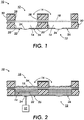
- a sensor 10 includes osmotic reaction cells 12, each including enclosed lower or first wells 14 and upper or second wells 16 separated by a semi-permeable membrane 18.
- Each first well 14, includes side walls 20, and a bottom surface 22 defining an opening.
- a flexible diaphragm 24 is fabricated in or otherwise disposed in the opening provided in bottom surface 22.
- the side walls 20, bottom surface 22, and flexible diaphragm 24, together form an interior chamber into which fluid is introduced via a fluid input 26.
- Second wells 16 are defined by side walls 28 and the semi-permeable membrane 18, which forms a bottom surface of the second wells 16.
- the upper end of second wells 16 is shown to be open to permit the introduction of fluid.
- the reaction cells 12, continue to the left and to the right 30, as shown in the figure, when the cells 12 are part of a large array of osmotic cells.
- fluid input 26 may be arranged in any of a number of well known designs, such as a check valve or one way valve, to ensure fluid provided to each lower well 14 is maintained within the well.
- the upper end of second wells 16 may be enclosed, and a fluid input, such as 26 of first wells 14, will permit the introduction of fluid.
- FIGURE 1 shows the semi-permeable membrane 18 as continuous and extending through the walls 20 of the reaction cells 12, such an arrangement is not required in this embodiment, and the semi-permeable membrane 18 may instead be discontinuous and extend only between the walls of the reaction cells 12.
- the first wells 14 are filled through the input 26 with a reference solution 32 containing a carrier fluid and a reference material.
- This reference material can be a material of interest of which the level of reactivity with a second material of interest is desired to be known, such as an antibody.
- the reference material may be a surrogate material that is non-reactinq either with itself or with other solutes (if present) in the reference solution at the desired concentration. What is desired in the reference solution is a solution having a total number of solute molecules that will not change.
- the reference material may only contain a carrier fluid, without any reference material or other solutes dissolved therein.
- the reference material will be described as being an antibody, although any other non-reacting material is also suitable as discussed above.
- the identity of the carrier fluid will vary depending on the identity of the antibody. However, the carrier fluid is chosen whereby the antibody is at least partially soluble in the carrier fluid at conditions (e.g. temperature, etc.) under which testing will be carried out.
- a reaction mixture 34 containing a carrier fluid as well as both an antibody and an antigen species is introduced into the second wells 16 of the reaction cells.
- the carrier fluid in the reaction mixture 34 and the reference solution 32 may commonly be the same.
- embodiments are discussed herein in which the total antibody and antigen concentration in the second wells 16 matches (i.e. is equal to) the antibody concentration in the first wells 14. It is to be appreciated however, that the concentration in the first wells 14 and second wells 16 do not need to match. For example, particularly if a site (or well) is used as reference site (or well) the concentrations need not be equal.
- first wells 14 are filled with reference solution 32
- second wells 16 are filled with reaction mixture 34
- an opposite filling of the wells may at times be appropriate, where the first wells are filled with the reaction mixture 34 and the second wells 16 are filled with the solution 32.
- the amount of solution in both the first and second wells is selected based on the size of the wells as well as other considerations.
- the embodiments described herein are well suited to test for reactions at reactant concentrations of preferably in the range of approximately 5 x 10 -5 to 10 -7 M, and more preferably down to approximately 5 x 10 -6 to 10 -7 M, assuming a solution amount of approximately 0.1 microliters to 100 microliters.
- the wells may be approximately 1 mm on a side and approximately 100 microns deep for a total volume of 0.1 ⁇ l,
- the embodiments should not be construed as being limited to such ranges or geometric shapes, and the principles of operation can be applied to larger or smaller wells, solution amounts, and concentrations of species therein.
- the volume of each well is typically from about 0.05 ⁇ l to about 100 ⁇ l.
- the size of the cells and amount of fluid are appropriately selected based on the pressure levels to be sensed. Therefore, the disclosed components and the fluid amounts are matched to provide a temperature equilibrium across the fluid in the wells, whereby an undesirable temperature gradient is avoided which might otherwise result in inaccurate measurements of volumes of interest.
- Each reaction cell may be filled via any known method, such as through the use of micropipets or any other fluid delivery system.
- One method contemplated by the inventors is through the use of a delivery system similar to that used in high end ink jet printing devices including acoustic drop ejection systems.
- a delivery system similar to that used in high end ink jet printing devices including acoustic drop ejection systems Such systems are known in the art and may be readily adapted for use with the exemplary embodiments of present embodiments.
- robotic liquid sample delivery systems to deliver samples to these chambers.
- all of the first wells 14 will contain the same solution, in which case a closed liquid delivery system can be used to deliver sample to all chambers
- the semi-permeable membrane 18 is selected such that it is permeable to the carrier fluid, but impermeable to the antibody, the antigen, and any reaction products formed between the two.
- the case is considered where the total antibody and antigen concentration in the second wells 16 matches the antibody concentration in the first wells 14.
- concentration when there is no reaction between the antibody and the antigen, then the difference in osmotic pressure between a first and second well is negligible or zero. In that case, with the upper or second well at atmospheric pressure, the lower or first well also tends toward that same pressure, after the gravitational effect on pressure is taken into account for the height of the liquid.
- Suitable membranes are known in the art and include, for example, various dialysis membranes available from, among others, Fisher Scientific. These membranes have, for example, molecular weight cutoffs ranging from 100 Dalton to 300,000 Dalton, which are appropriate for the ranges and types of reactants described herein.
- the semi-permeable membrane does not need to be impermeable to all components in both the first and second materials as well as products formed therefrom. Rather, the present embodiments can be used to determine the occurrence and extent of reaction between the first and second materials so long as the molar concentration of impermeable components changes when a reaction in the reaction cell occurs. For example, it may be the case where a catalytic antibody reacts with an impermeable molecule, breaking it up into parts that are all permeable. In such a case, there are permeable products, but the number of impermeable components changes from two (i.e. the catalytic antibody plus the impermeable molecule) to one (catalytic antibody).
- any binding or catalytic reaction between the antibody and the antigen alters the number of total solute molecules in the second well, when both species are impermeable, which in turn changes the osmotic pressure difference between the first and second wells in a reaction cell 12.
- N moles per unit volume of the antigen compound react with N moles per unit volume of antibody to produce N moles per unit volume of antigen-antibody complex. Accordingly, the osmotic pressure due to these two components drops to 1/2 its previous level.
- N moles per unit volume of antigen molecule may react with N moles per unit volume of antibody to form 2N moles per unit volume of antigen fragments plus the original N moles per unit volume of catalytic antibody, increasing the osmotic pressure in the second cell and resulting in the osmotic pressure in the first well being smaller than the osmotic pressure in the second well.
- N moles per unit volume of antigen molecule may react with N moles per unit volume of antibody to form 2N moles per unit volume of antigen fragments plus the original N moles per unit volume of catalytic antibody, increasing the osmotic pressure in the second cell and resulting in the osmotic pressure in the first well being smaller than the osmotic pressure in the second well.
- ⁇ cRT , where ⁇ is osmotic pressure, c is molar concentration of solute, R is the gas constant, and T is the absolute temperature.
- ⁇ osmotic pressure
- c molar concentration of solute
- R the gas constant
- T the absolute temperature.
- the diaphragm preferably has an inherent spring constant such that the deflection of the diaphragm in response to osmotic pressure changes can be detected.
- y is the deflection
- I is the radius of the diaphragm
- P is the pressure
- E Young's modulus (which are typically in the range of 0.3-10 MPa for typical electroactive polymer diaphragm materials of interest as described below)
- ⁇ Poisson's ratio
- t is the thickness of the diaphragm.
- Suitable materials for use in the diaphragm in general include metals, as well as plastics and elastomers such as acrylic and silicone elastomers.
- E for most common metals ranges from about 45 GPa to 200 GPa.
- the thickness of the diaphragm might range, e.g., from about 20 nm to 300 nm.
- Typical plastics may have E ranging from about 100 MPa to 4.5 GPa. Diaphragms made from such materials may have a corresponding greater thickness than metal ones.
- An exemplary class of elastomers suitable for use as the diaphragm according to the present invention include those used in the industry as electroactive polymers (EAP) and described by R. Pelrine, R. Kornbluh, Q. Pei and J. Joseph (Science, vol. 287, pp. 836-839, Feb. 4, 2000 ). These include VHB 4910 acrylic (from 3M Corporation of Minneapolis, Minnesota), HS3 silicone (from Dow Corning of Midland, Michigan), and CF 19-2186 silicone (from NuSil Technology of Carpenteria, California). Such electroactive polymers have typical E values in the range of about 0.3 MPa to 10 MPa. Diaphragms made from such materials have typical thicknesses from about 1 to about 50 ⁇ m.
- EAP electroactive polymers
- the deflection of the diaphragm is measured using several techniques, which may be applied to each reaction cell of an array.
- the change of deflection of the diaphragm is measured by a change in capacitance.
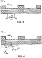
- a sensor 110 including one or more osmotic reaction cells 112 as previously described is shown.
- a capacitance detector 150 is connected across the diaphragm by two lead wires 152. A deflection in the diaphragm causes a change in capacitance.
- the change in area of the diaphragm due to the osmotic pressure differential in the two wells causes a change in the capacitance across the diaphragm.
- Frequency-based measurements of the capacitance may be used to lower the noise in the signal, and sensors in separate control and screening samples can be joined in one circuit to enable common mode rejection.
- the flexible diaphragm is preferably coated on both sides with a conductive material as is known in the art.
- the deflection of the diaphragm is measured using a cantilever detector system, similar in principle to those used in atomic force microscopes.
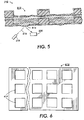
- a sensor 210 including one or more reaction cells 212 as previously described is shown.
- a cantilever including an arm 214 and a tip 216 is positioned such that the tip 216 is in contact with the flexible diaphragm 218.
- the tip 216 moves with the diaphragm 218, following the deflection of the diaphragm, if any,
- the reflection of a light source 220 off of the cantilever varies with the movement of the cantilever, and is reflected onto a detector 222, which, when calibrated, is used to measure the magnitude of deflection of the diaphragm to thereby determine osmotic pressure changes.
- the light source may be a laser, diode or other appropriate light-emitting device, and the detector may be a split-diode detector, or other detector, which will perform the required detection of the movement of the reflected light. Movement of the cantilever may also be detected by measuring capacitance changes in the cantilever, as well as changes in resonance of the cantilever as a function of deflection.
- the deflection of the diaphragm is measured by observing a reflected light directly from the diaphragm.
- a sensor 310 including one or more reaction cells 312 as previously described is shown.
- a change in shape of the diaphragm 314 alters the angle of reflection of a light 316 from a light source 318 impacting on the diaphragm, which may be detected by a detector 320.
- This change in the angle of reflection is correlated to the magnitude of deflection of the diaphragm 314.
- the light source and detector may be such as those described in relation to FIGURE 4 .
- additional means for measuring the deflection of the diaphragm are possible.
- FIGURE 6 illustrates an array 612 of individual reaction cells 614 according to any one of the embodiments discussed above.
- Such an array allows for the testing of a large number of samples using the same or different materials of interest and probe compounds in individual reaction cells. Therefore, it is possible to not only perform massive parallel investigations, which is very beneficial for use in areas which employ combinatorial chemistry, but it is also possible to perform distinct investigations by filling reaction cells of the array with distinct solutions and/or reaction mixtures.
Landscapes
- General Health & Medical Sciences (AREA)
- Health & Medical Sciences (AREA)
- Life Sciences & Earth Sciences (AREA)
- Chemical & Material Sciences (AREA)
- Analytical Chemistry (AREA)
- Biochemistry (AREA)
- Physics & Mathematics (AREA)
- General Physics & Mathematics (AREA)
- Immunology (AREA)
- Pathology (AREA)
- Apparatus Associated With Microorganisms And Enzymes (AREA)
- Investigating Or Analyzing Materials By The Use Of Electric Means (AREA)
- Investigating Or Analyzing Non-Biological Materials By The Use Of Chemical Means (AREA)
Claims (7)
- Verfahren zum Überwachen der Reaktivität in Reaktionen zwischen einem ersten und einem zweiten relevanten Material, wobei das Verfahren folgende Schritte umfasst:(a) Bereitstellen eines Osmosereaktionsdetektors (10), umfassend eine semipermeable Membran (18) und einen Drucksensor (31);(b) Einführen von einem aus einer Reaktionsmischung (31) und einer Referenzlösung (32) in den Osmosereaktionsdetektor, wobei die Reaktionsmischung ein Trägerfluid, ein erstes relevantes Material und ein zweites relevantes Material umfasst und die Referenzlösung eines oder eine Kombination aus dem ersten Material, dem zweiten Material, einem Ersatz-Referenzmaterial und einem Trägerfluid umfasst;(c) Positionieren des Osmosereaktionsdetektors solcherart, dass die semipermeable Membran (18) in Fluidkontakt mit der Reaktionsmischung und der Referenzlösung steht und dazwischen positioniert ist; und(d) Überwachen einer Ausgabe von dem Drucksensor (31) nach dem Positionieren des Osmosereaktionsdetektors, wobei Druckänderungen als Ergebnis einer Änderung in der Konzentration in der Reaktionsmischung (34) von einem oder mehreren aus dem ersten Material, dem zweiten Material, dem Ersatz-Referenzmaterial oder Reaktionsprodukten auftreten, die aus dem ersten und zweiten Material gebildet werden,wobei der Drucksensor eine flexible Membran umfasst, die eine Öffnung einer inneren Kammer des Osmosereaktionsdetektors (10) bedeckt, wobei eine Änderung des osmotischen Drucks in der Kammer durch Messen der Auslenkung der flexiblen Membran gemessen wird, welche die Öffnung abdeckt,
dadurch gekennzeichnet, dass
die flexible Membran ein elektroaktives Polymer umfasst, das einen Elastizitätsmodul im Bereich von 0,3 MPa bis 10 MPa und eine Dicke im Bereich von 1 bis 50 µm aufweist. - Verfahren nach Anspruch 1, wobei das Verfahren unter Verwendung einer Vielzahl von Osmosereaktionsdetektoren durchgeführt wird, wobei mindestens zwei Osmosereaktionsdetektoren aus der Vielzahl mindestens ein anderes erstes oder zweites Material verwenden.
- Verfahren nach Anspruch 2, wobei die Verfahren zum Überwachen von mindestens zwei Osmosereaktionsdetektoren im Wesentlichen gleichzeitig durchgeführt werden.
- Verfahren nach Anspruch 1, wobei das Verfahren die Reaktionen in den Osmosereaktionsdetektoren bei einer Anfangskonzentration des ersten und zweiten relevanten Materials in der Reaktionsmischung im Bereich von etwa 5x10⁻⁵ M to 5X10⁻⁷ M überwacht.
- Verfahren nach Anspruch 1, wobei das Verfahren die Reaktionen bei einer so niedrigen Anfangskonzentration des ersten und zweiten relevanten Materials in der Reaktionsmischung wie etwa 5X10⁻⁷ M überwacht.
- Verfahren nach Anspruch 1, wobei das Verfahren die osmotischen Druckänderungen in einem Bereich von etwa 1,2 N/m2 bis 130 N/m2 misst.
- Osmosereaktionsdetektor (10) zum Überwachen der Reaktivität in Reaktionen zwischen einem relevanten ersten Material und einem relevanten zweiten Material durch Messen von Druckänderungen in dem Osmosereaktionsdetektor als Ergebnis einer Änderung in der Konzentration von impermeablen Spezies in dem Osmosereaktionsdetektor, wobei der Detektor umfasst:einen Körper, der eine innere Kammer definiert;eine semipermeable Membran (18), die in den Körper integriert ist, wobei die semipermeable Membran für das erste und zweite relevante Material sowie daraus gebildete Reaktionsprodukte impermeabel und permeabel für das Trägerfluid ist; undeinen Drucksensor (31) zum Messen von Änderungen im osmotischen Druck des Detektors,wobei der Drucksensor eine flexible Membran umfasst, die eine Öffnung einer inneren Kammer des Osmosereaktionsdetektors (10) bedeckt, wobei eine Änderung des osmotischen Drucks in der Kammer durch Messen der Auslenkung der flexiblen Membran gemessen wird, welche die Öffnung abdeckt,dadurch gekennzeichnet, dassdie flexible Membran ein elektroaktives Polymer umfasst, das einen Elastizitätsmodul im Bereich von 0,3 MPa bis 10 MPa und eine Dicke im Bereich von 1 bis 50 µm aufweist.
Applications Claiming Priority (2)
| Application Number | Priority Date | Filing Date | Title |
|---|---|---|---|
| US739853 | 2003-12-18 | ||
| US10/739,853 US7553669B2 (en) | 2003-12-18 | 2003-12-18 | Osmotic reaction detector for monitoring biological and non-biological reactions |
Publications (3)
| Publication Number | Publication Date |
|---|---|
| EP1544597A2 EP1544597A2 (de) | 2005-06-22 |
| EP1544597A3 EP1544597A3 (de) | 2013-05-15 |
| EP1544597B1 true EP1544597B1 (de) | 2017-04-19 |
Family
ID=34523196
Family Applications (1)
| Application Number | Title | Priority Date | Filing Date |
|---|---|---|---|
| EP04029152.8A Expired - Lifetime EP1544597B1 (de) | 2003-12-18 | 2004-12-09 | Osmose-detektor zur Erfassung biologischer und nicht-biologischer Reaktionen |
Country Status (3)
| Country | Link |
|---|---|
| US (2) | US7553669B2 (de) |
| EP (1) | EP1544597B1 (de) |
| JP (1) | JP4612404B2 (de) |
Families Citing this family (7)
| Publication number | Priority date | Publication date | Assignee | Title |
|---|---|---|---|---|
| US7615375B2 (en) * | 2003-12-18 | 2009-11-10 | Xerox Corporation | Osmotic reaction cell for monitoring biological and non-biological reactions |
| US7553669B2 (en) * | 2003-12-18 | 2009-06-30 | Palo Alto Resaerch Center Incorporated | Osmotic reaction detector for monitoring biological and non-biological reactions |
| US7790111B2 (en) * | 2004-12-20 | 2010-09-07 | Palo Alto Research Center Incorporated | Osmotic reaction detector for detecting biological and non-biological reactions |
| DK2185910T3 (en) * | 2007-08-20 | 2018-10-22 | Lifecare As | device and method for measuring amplified osmotic pressure in a reference cavity |
| US10082500B2 (en) | 2013-08-22 | 2018-09-25 | Franz Baudenbacher | Device and method for detecting a target analyte |
| KR101647978B1 (ko) * | 2014-03-17 | 2016-08-24 | 한국과학기술원 | 마이크로캡슐을 이용한 삼투압의 직접 측정 방법 |
| US20220305181A1 (en) * | 2021-03-23 | 2022-09-29 | Nephria Bio, Inc. | Systems, devices, and methods for continuous ambulatory renal replacement therapy |
Citations (1)
| Publication number | Priority date | Publication date | Assignee | Title |
|---|---|---|---|---|
| WO2004083828A1 (de) * | 2003-03-17 | 2004-09-30 | Disetronic Licensing Ag | Sensorisches membran-osmometer und osmotisches messverfahren zur quantitativen bestimmung niedermolekularer affinitätsliganden |
Family Cites Families (31)
| Publication number | Priority date | Publication date | Assignee | Title |
|---|---|---|---|---|
| US3195346A (en) * | 1963-01-14 | 1965-07-20 | Mechrolab Inc | Automatic osmometer |
| JPS501707B1 (de) * | 1969-12-20 | 1975-01-21 | ||
| US3628373A (en) * | 1970-06-29 | 1971-12-21 | Beckman Instruments Inc | Pressure-measuring system |
| US4028931A (en) * | 1976-02-13 | 1977-06-14 | Cardio Pulminary Laboratory Research Foundation | Osmotic pressure sensing head |
| US4111203A (en) * | 1976-11-22 | 1978-09-05 | Alza Corporation | Osmotic system with means for improving delivery kinetics of system |
| DE3110183C2 (de) * | 1981-03-17 | 1983-12-01 | Franz Dr.-Ing. 1000 Berlin Wallner | Membranosmometer |
| US4475556A (en) * | 1983-01-03 | 1984-10-09 | Reiff Theodore R | Rapid measurement of colloid osmotic equilibrium pressure |
| JPS59182353A (ja) * | 1983-03-31 | 1984-10-17 | Agency Of Ind Science & Technol | 膜透過率測定装置 |
| DE3736230C1 (de) * | 1987-10-27 | 1989-03-30 | Kernforschungsanlage Juelich | Verfahren und Einrichtung zur selektiven Bestimmung des Gehaltes eines in einem Loesungsmittel geloesten Stoffes |
| JPH0224532A (ja) * | 1988-07-13 | 1990-01-26 | Nissho Corp | 半透膜式コロイド浸透圧計 |
| DE3825208C1 (de) * | 1988-07-25 | 1989-11-02 | Ernst Prof. Dr. 8581 Eckersdorf De Steudle | |
| JP2802344B2 (ja) | 1989-02-27 | 1998-09-24 | 農林水産省食品総合研究所長 | 浸透圧の測定方法及び装置 |
| JPH0715420B2 (ja) * | 1989-03-07 | 1995-02-22 | 日本電装株式会社 | 圧力センサ |
| FR2652736A1 (fr) * | 1989-10-06 | 1991-04-12 | Neftel Frederic | Dispositif implantable d'evaluation du taux de glucose. |
| FR2672994A1 (fr) | 1991-02-18 | 1992-08-21 | Bourgogne Technologies | Capteur de pression osmotique pour mesures en continu. |
| US5189917A (en) * | 1991-07-22 | 1993-03-02 | Trustees Of Boston University | Electrical mercury manometer |
| US5279793A (en) * | 1992-09-01 | 1994-01-18 | Glass Alexander J | Optical osmometer for chemical detection |
| US5388449A (en) * | 1993-07-06 | 1995-02-14 | Leveen; Harry H. | Osmolarity sensor |
| DE4407637C2 (de) * | 1994-03-08 | 1995-12-21 | Forschungszentrum Juelich Gmbh | Osmometer-Meßeinrichtung und Verfahren zur Bestimmung des Gehaltes des Analyts aus einer Stoffgemisch-Lösung |
| US6267003B1 (en) * | 1999-12-28 | 2001-07-31 | Eastman Kodak Company | Method for measuring changes in osmotic pressure |
| EP1029229A1 (de) * | 1997-09-30 | 2000-08-23 | M- Biotech, Inc. | Biosensor zur messung der konzentration eines organischen moleküls |
| WO2001081890A2 (en) * | 2000-04-22 | 2001-11-01 | M-Biotech, Inc. | Hydrogel biosensor and biosensor-based health alarm system |
| US6597499B2 (en) * | 2001-01-25 | 2003-07-22 | Olympus Optical Co., Ltd. | Total internal reflection fluorescence microscope having a conventional white-light source |
| GB0130518D0 (en) * | 2001-12-21 | 2002-02-06 | Univ Gent | Pulsed bio-agent delivery systems based on degradable polymer solutions or hydrogels |
| DE10392210T5 (de) | 2002-01-23 | 2004-12-23 | Danfoss A/S | Verfahren und Vorrichtung zum Überwachen einer analytischen Konzentration mittels einer Osmose-Differenz-Druckmessung |
| US7141210B2 (en) * | 2002-04-01 | 2006-11-28 | Palo Alto Research Center Incorporated | Apparatus and method for a nanocalorimeter for detecting chemical reactions |
| EP2299255A3 (de) * | 2002-08-06 | 2014-05-14 | The Regents of the University of California | Osmometrie an einem Tränenflüssigkeitsfilm |
| US20050130319A1 (en) * | 2003-12-15 | 2005-06-16 | Xerox Corporation | Molecular binding event detection using separation channels |
| US7553669B2 (en) * | 2003-12-18 | 2009-06-30 | Palo Alto Resaerch Center Incorporated | Osmotic reaction detector for monitoring biological and non-biological reactions |
| US7615375B2 (en) * | 2003-12-18 | 2009-11-10 | Xerox Corporation | Osmotic reaction cell for monitoring biological and non-biological reactions |
| US7790111B2 (en) * | 2004-12-20 | 2010-09-07 | Palo Alto Research Center Incorporated | Osmotic reaction detector for detecting biological and non-biological reactions |
-
2003
- 2003-12-18 US US10/739,853 patent/US7553669B2/en active Active
-
2004
- 2004-12-09 EP EP04029152.8A patent/EP1544597B1/de not_active Expired - Lifetime
- 2004-12-17 JP JP2004366123A patent/JP4612404B2/ja not_active Expired - Fee Related
-
2009
- 2009-06-29 US US12/493,668 patent/US7794662B2/en not_active Expired - Fee Related
Patent Citations (1)
| Publication number | Priority date | Publication date | Assignee | Title |
|---|---|---|---|---|
| WO2004083828A1 (de) * | 2003-03-17 | 2004-09-30 | Disetronic Licensing Ag | Sensorisches membran-osmometer und osmotisches messverfahren zur quantitativen bestimmung niedermolekularer affinitätsliganden |
Non-Patent Citations (1)
| Title |
|---|
| "Electroactive Polymers for Robotic Applications", 31 December 2007, SPRINGER, London, ISBN: 978-1-84-628371-0, article R SAMATHAM ET AL: "Active Polymers: An overview", pages: 1 - 36, XP055176809 * |
Also Published As
| Publication number | Publication date |
|---|---|
| EP1544597A2 (de) | 2005-06-22 |
| US7553669B2 (en) | 2009-06-30 |
| EP1544597A3 (de) | 2013-05-15 |
| JP4612404B2 (ja) | 2011-01-12 |
| US20050136544A1 (en) | 2005-06-23 |
| US20090260425A1 (en) | 2009-10-22 |
| US7794662B2 (en) | 2010-09-14 |
| JP2005181330A (ja) | 2005-07-07 |
Similar Documents
| Publication | Publication Date | Title |
|---|---|---|
| US7851226B2 (en) | Osmotic reaction detector for monitoring biological and non-biological reactions | |
| EP1207958B1 (de) | Sensor für ein mikrofluidisches bearbeitungssystem | |
| US6575020B1 (en) | Transducer for microfluid handling system | |
| KR100613398B1 (ko) | 캔틸레버 센서형 분석 시스템, 제조 방법 및 이를 이용한극미세 물질 감지 방법 | |
| JP4347564B2 (ja) | 生化学分析方法と装置 | |
| US7666680B2 (en) | Osmotic reaction detector for detecting biological and non-biological reactions | |
| US7794662B2 (en) | Osmotic reaction detector for monitoring biological and non-biological reactions | |
| EP1481246B1 (de) | Gerät und methode zur analytischen messung und immuntest | |
| CN101506643A (zh) | 细胞分析装置及方法 | |
| CN107884456B (zh) | 检测流体状态的传感器和方法以及控制样品制备的系统 | |
| EP2458382A1 (de) | Analysevorrichtung mit mehreren Testzonen, Verfahren mit der Vorrichtung | |
| US7389679B2 (en) | Measurement cell and method for the analysis of liquids | |
| EP2397224A1 (de) | Vorrichtung und Plattform zur Multiplex-Analyse | |
| US20030013147A1 (en) | Test system based on microcapillaries | |
| US20080261297A1 (en) | Assay Device | |
| Suda et al. | Micromachined detectors for an enzyme-based FIA | |
| EP1650564B1 (de) | Mechanochemischer typensensor | |
| EP1617211A1 (de) | Verfahren zur Herstellung eines Sensors | |
| Fatikow et al. | Microsensors: Principles and Examples | |
| AU2006246981A1 (en) | Assay device | |
| HK1168901A (en) | Assay device with mutiple test zones and method using it |
Legal Events
| Date | Code | Title | Description |
|---|---|---|---|
| PUAI | Public reference made under article 153(3) epc to a published international application that has entered the european phase |
Free format text: ORIGINAL CODE: 0009012 |
|
| AK | Designated contracting states |
Kind code of ref document: A2 Designated state(s): AT BE BG CH CY CZ DE DK EE ES FI FR GB GR HU IE IS IT LI LT LU MC NL PL PT RO SE SI SK TR |
|
| AX | Request for extension of the european patent |
Extension state: AL BA HR LV MK YU |
|
| PUAL | Search report despatched |
Free format text: ORIGINAL CODE: 0009013 |
|
| AK | Designated contracting states |
Kind code of ref document: A3 Designated state(s): AT BE BG CH CY CZ DE DK EE ES FI FR GB GR HU IE IS IT LI LT LU MC NL PL PT RO SE SI SK TR |
|
| AX | Request for extension of the european patent |
Extension state: AL BA HR LV MK YU |
|
| RIC1 | Information provided on ipc code assigned before grant |
Ipc: G01N 35/02 20060101ALN20130405BHEP Ipc: G01N 13/04 20060101AFI20130405BHEP |
|
| 17P | Request for examination filed |
Effective date: 20131115 |
|
| RBV | Designated contracting states (corrected) |
Designated state(s): AT BE BG CH CY CZ DE DK EE ES FI FR GB GR HU IE IS IT LI LT LU MC NL PL PT RO SE SI SK TR |
|
| AKX | Designation fees paid |
Designated state(s): DE FR GB |
|
| 17Q | First examination report despatched |
Effective date: 20140411 |
|
| GRAP | Despatch of communication of intention to grant a patent |
Free format text: ORIGINAL CODE: EPIDOSNIGR1 |
|
| RIC1 | Information provided on ipc code assigned before grant |
Ipc: G01N 13/04 20060101AFI20161102BHEP Ipc: G01N 35/02 20060101ALN20161102BHEP |
|
| RIC1 | Information provided on ipc code assigned before grant |
Ipc: G01N 35/02 20060101ALN20161110BHEP Ipc: G01N 13/04 20060101AFI20161110BHEP |
|
| INTG | Intention to grant announced |
Effective date: 20161122 |
|
| GRAS | Grant fee paid |
Free format text: ORIGINAL CODE: EPIDOSNIGR3 |
|
| GRAA | (expected) grant |
Free format text: ORIGINAL CODE: 0009210 |
|
| AK | Designated contracting states |
Kind code of ref document: B1 Designated state(s): DE FR GB |
|
| REG | Reference to a national code |
Ref country code: GB Ref legal event code: FG4D |
|
| REG | Reference to a national code |
Ref country code: DE Ref legal event code: R096 Ref document number: 602004051102 Country of ref document: DE |
|
| REG | Reference to a national code |
Ref country code: FR Ref legal event code: PLFP Year of fee payment: 14 |
|
| REG | Reference to a national code |
Ref country code: DE Ref legal event code: R097 Ref document number: 602004051102 Country of ref document: DE |
|
| PLBE | No opposition filed within time limit |
Free format text: ORIGINAL CODE: 0009261 |
|
| STAA | Information on the status of an ep patent application or granted ep patent |
Free format text: STATUS: NO OPPOSITION FILED WITHIN TIME LIMIT |
|
| 26N | No opposition filed |
Effective date: 20180122 |
|
| PGFP | Annual fee paid to national office [announced via postgrant information from national office to epo] |
Ref country code: FR Payment date: 20191120 Year of fee payment: 16 |
|
| PGFP | Annual fee paid to national office [announced via postgrant information from national office to epo] |
Ref country code: GB Payment date: 20191122 Year of fee payment: 16 |
|
| PGFP | Annual fee paid to national office [announced via postgrant information from national office to epo] |
Ref country code: DE Payment date: 20201119 Year of fee payment: 17 |
|
| GBPC | Gb: european patent ceased through non-payment of renewal fee |
Effective date: 20201209 |
|
| PG25 | Lapsed in a contracting state [announced via postgrant information from national office to epo] |
Ref country code: FR Free format text: LAPSE BECAUSE OF NON-PAYMENT OF DUE FEES Effective date: 20201231 |
|
| PG25 | Lapsed in a contracting state [announced via postgrant information from national office to epo] |
Ref country code: GB Free format text: LAPSE BECAUSE OF NON-PAYMENT OF DUE FEES Effective date: 20201209 |
|
| REG | Reference to a national code |
Ref country code: DE Ref legal event code: R119 Ref document number: 602004051102 Country of ref document: DE |
|
| PG25 | Lapsed in a contracting state [announced via postgrant information from national office to epo] |
Ref country code: DE Free format text: LAPSE BECAUSE OF NON-PAYMENT OF DUE FEES Effective date: 20220701 |