EP1544531A1 - Releasable tube coupling - Google Patents
Releasable tube coupling Download PDFInfo
- Publication number
- EP1544531A1 EP1544531A1 EP04028777A EP04028777A EP1544531A1 EP 1544531 A1 EP1544531 A1 EP 1544531A1 EP 04028777 A EP04028777 A EP 04028777A EP 04028777 A EP04028777 A EP 04028777A EP 1544531 A1 EP1544531 A1 EP 1544531A1
- Authority
- EP
- European Patent Office
- Prior art keywords
- bolt
- connection
- connection according
- detachable connection
- ring
- Prior art date
- Legal status (The legal status is an assumption and is not a legal conclusion. Google has not performed a legal analysis and makes no representation as to the accuracy of the status listed.)
- Granted
Links
- 230000008878 coupling Effects 0.000 title 1
- 238000010168 coupling process Methods 0.000 title 1
- 238000005859 coupling reaction Methods 0.000 title 1
- 239000000463 material Substances 0.000 claims description 9
- 238000007789 sealing Methods 0.000 claims description 4
- 239000000919 ceramic Substances 0.000 claims description 3
- 239000000725 suspension Substances 0.000 claims description 3
- UGFAIRIUMAVXCW-UHFFFAOYSA-N Carbon monoxide Chemical compound [O+]#[C-] UGFAIRIUMAVXCW-UHFFFAOYSA-N 0.000 claims description 2
- 239000003546 flue gas Substances 0.000 claims description 2
- 238000000034 method Methods 0.000 claims 1
- 150000001875 compounds Chemical class 0.000 description 5
- 244000089486 Phragmites australis subsp australis Species 0.000 description 2
- 230000007797 corrosion Effects 0.000 description 2
- 238000005260 corrosion Methods 0.000 description 2
- 229910000990 Ni alloy Inorganic materials 0.000 description 1
- 229910000831 Steel Inorganic materials 0.000 description 1
- 229910010293 ceramic material Inorganic materials 0.000 description 1
- VNNRSPGTAMTISX-UHFFFAOYSA-N chromium nickel Chemical compound [Cr].[Ni] VNNRSPGTAMTISX-UHFFFAOYSA-N 0.000 description 1
- 230000001419 dependent effect Effects 0.000 description 1
- 239000007769 metal material Substances 0.000 description 1
- 239000003566 sealing material Substances 0.000 description 1
- 239000007921 spray Substances 0.000 description 1
- 230000006641 stabilisation Effects 0.000 description 1
- 238000011105 stabilization Methods 0.000 description 1
- 239000010935 stainless steel Substances 0.000 description 1
- 229910001220 stainless steel Inorganic materials 0.000 description 1
- 239000010959 steel Substances 0.000 description 1
Images


Classifications
-
- F—MECHANICAL ENGINEERING; LIGHTING; HEATING; WEAPONS; BLASTING
- F16—ENGINEERING ELEMENTS AND UNITS; GENERAL MEASURES FOR PRODUCING AND MAINTAINING EFFECTIVE FUNCTIONING OF MACHINES OR INSTALLATIONS; THERMAL INSULATION IN GENERAL
- F16L—PIPES; JOINTS OR FITTINGS FOR PIPES; SUPPORTS FOR PIPES, CABLES OR PROTECTIVE TUBING; MEANS FOR THERMAL INSULATION IN GENERAL
- F16L25/00—Constructive types of pipe joints not provided for in groups F16L13/00 - F16L23/00 ; Details of pipe joints not otherwise provided for, e.g. electrically conducting or insulating means
- F16L25/0072—Joints for pipes of dissimilar materials
-
- F—MECHANICAL ENGINEERING; LIGHTING; HEATING; WEAPONS; BLASTING
- F16—ENGINEERING ELEMENTS AND UNITS; GENERAL MEASURES FOR PRODUCING AND MAINTAINING EFFECTIVE FUNCTIONING OF MACHINES OR INSTALLATIONS; THERMAL INSULATION IN GENERAL
- F16L—PIPES; JOINTS OR FITTINGS FOR PIPES; SUPPORTS FOR PIPES, CABLES OR PROTECTIVE TUBING; MEANS FOR THERMAL INSULATION IN GENERAL
- F16L37/00—Couplings of the quick-acting type
- F16L37/08—Couplings of the quick-acting type in which the connection between abutting or axially overlapping ends is maintained by locking members
- F16L37/12—Couplings of the quick-acting type in which the connection between abutting or axially overlapping ends is maintained by locking members using hooks, pawls or other movable or insertable locking members
- F16L37/14—Joints secured by inserting between mating surfaces an element, e.g. a piece of wire, a pin, a chain
- F16L37/142—Joints secured by inserting between mating surfaces an element, e.g. a piece of wire, a pin, a chain where the securing element is inserted tangentially
- F16L37/146—Joints secured by inserting between mating surfaces an element, e.g. a piece of wire, a pin, a chain where the securing element is inserted tangentially the securing element being a rigid pin, screw or the like
Definitions
- the invention relates to a releasable connection for pipes according to the preamble of the first claim.
- the detachable connection can be used in particular for suspension nozzles and attachments to suspension distribution pipes in flue gas scrubbers and for pipes which come into contact externally with aggressive media and in which aggressive media are transported.
- screw or clamp connections are known in the prior art.
- the technical function is usually dependent on the spray direction in particular.
- the screw and clamp connections is usually the required Non-rotation guaranteed.
- the compounds are exposed by the aggressive media to high wear, which means that they must be renewed frequently.
- highly corrosion-resistant chromium-nickel alloy-based fasteners are used, which are very expensive.
- that the components to be joined may consist of different materials, are usually z. As plastic, ceramic or special metal materials.
- a terminal side represents ring-shaped limiting part, which may be bell-shaped and a flat Surface represents.
- the flat surface serves to dense with the second connector part Make connection.
- the limiting annular or bell-shaped part serves to take the modified collar of the other side so that a positive Connection is present.
- the ring-shaped limiting or bell-shaped part above and below a hole for one Bolt has.
- holding surfaces are flat surfaces in an angle ⁇ between 10 and 60 ° to the plane or plane surface, in particular of 20 30th provided up to 45 °.
- the holding surfaces can continue to stabilize the compound have a groove in the second terminal side represent.
- the two sides of the tube must be inserted into each other so that the two levels Surfaces lie on one another, wherein the second terminal side with their retaining surfaces so it is twisted that the holding surfaces are located at the point in the annular limiting part has holes for the bolt.
- a sealing element is arranged, which both parts against each other seals and ensures that a necessary pressure between the two parts is. The restoring forces of the sealing material cause the securing of the bolt in the Bore the annular limiting part or the bell sleeve.
- the bolt has a conical end at least on one side. Furthermore, the connection is advantageous if the first terminal side of a ceramic material and the second terminal side made of a different material exists z. B. plastic and thus a compound by thermal joining not possible is.
- the O-ring can be made of rubber.
- the bolts can be made of steel, stainless steel or consist of another rigid material.
- first terminal side 1 aa has an annular limiting part 6 or a bell sleeve, in the top and bottom holes 4 are arranged through the bolt 3 protrude, a second terminal side 2 detachably connect to the first terminal side 1, wherein the second terminal side 2 has a further outer diameter 12.
- Both connection sides 1, 2 have flat surfaces 7, which lie against each other, wherein an O-ring 5 seals both parts 1, 2 against each other. The required contact pressure for the seal is realized via the bolt 3.
- Figure 2 shows the view A of Figure 1, from which it can be seen that the top and bottom bolts 3 are arranged in the annular limiting part 6, wherein the bolts 3 on one side have a conical end 8 to facilitate assembly.
- FIGS. 4 and 5 show the second connection side 2 for the connection part 9 in different views.
- the subsequent part 9 (second terminal side) is made of the material, which is easier to produce compared to the first terminal side.
- FIG. 3 shows the bolt 3 with its conical end 8.
- FIG. 6 shows the O-ring 5 in side view.
- Figures 7 and 8 show the first terminal side with its annular or bell-shaped part 6, is introduced through the top and bottom of the bore 4, wherein in the flat surface 7, the groove 11 has been introduced for the O-ring 5.
- the connection side 1 with the bell sleeve consists of a material which is particularly suitable for aggressive and highly corrosive media.
- the bolt 3 should be made of rigid high corrosion resistant material.
- FIG. 9 shows a variant in which the holding surface 10 is designed with a groove 12 for better stabilization.
- the proposed solution has the advantage that a detachable connection for pipes that out may consist of different materials that are externally from aggressive media flows around and in which aggressive media are transported, fast and easy Way is inexpensive to produce and with little effort in the predetermined position can be mounted.
Abstract
Description
Die Erfindung betrifft eine lösbare Verbindung für Rohre entsprechend dem Oberbegriff des
ersten Anspruches.
Die lösbare Verbindung ist insbesondere einsetzbar für Suspensionsdüsen und Anbauten an
Suspensionsverteilerrohren in Rauchgaswäschern sowie für Rohre die äußerlich mit
aggressiven Medien in Kontakt kommen und in denen aggressive Medien transportiert
werden. Für derartige Rohrverbindungen sind nach dem Stand der Technik Flansch-,
Schraub- oder Schellenverbindungen bekannt. Bei dem Einsatz von Düsen ist die technische
Funktion üblicherweise von der Sprührichtung in besonderem Maße abhängig. Bei den
Schraub- und Schellenverbindungen ist in der Regel die dafür erforderliche
Verdrehsicherheit nicht gewährleistet. Weiterhin sind die Verbindungen durch die
aggressiven Medien einem hohen Verschleiß ausgesetzt, was dazu führt, daß diese häufig
erneuert werden müssen. Um das zu vermeiden, werden hoch korrosionsbeständige
Verbindungselemente auf der Basis einer Chrom-Nickel-Legierung eingesetzt, die sehr teuer
sind. Erschwerend kommt hinzu, daß die zu verbindenden Bauteile aus unterschiedlichen
Materialien bestehen können, üblich sind z. B. Kunststoff, Keramik oder metallische
Sondermaterialien.The invention relates to a releasable connection for pipes according to the preamble of the first claim.
The detachable connection can be used in particular for suspension nozzles and attachments to suspension distribution pipes in flue gas scrubbers and for pipes which come into contact externally with aggressive media and in which aggressive media are transported. For such pipe connections flange, screw or clamp connections are known in the prior art. When using nozzles, the technical function is usually dependent on the spray direction in particular. In the screw and clamp connections is usually the required
Non-rotation guaranteed. Furthermore, the compounds are exposed by the aggressive media to high wear, which means that they must be renewed frequently. To avoid this, highly corrosion-resistant chromium-nickel alloy-based fasteners are used, which are very expensive. To make matters worse, that the components to be joined may consist of different materials, are usually z. As plastic, ceramic or special metal materials.
Aus WO 96 10 712 A1 ist eine Verbindung zwischen Rohren bekannt, wobei die eine Seite ein glockenförmiges Anschlußteil aufweist, welches mit einem anderen Rohr dadurch verbunden wird, daß ein U-förmiges Teil in Öffnungen im Umfang des ersten Teiles eingeschoben wird und auf diese Weise das zweite Teil im glockenförmigen Umfang des ersten Teiles hält. Nachteilig an dieser Lösung ist, daß beide Teile gegeneinander verdrehbar sind, also keine Fixierung zwischen beiden Teilen vorhanden ist. Dadurch können sich beide Teile zueinander bewegen, was Beschädigungen oder Undichtheiten zur Folge haben kann. Insbesondere für aggressive Medien sind daher diese Verbindungen ungeeignet.From WO 96 10 712 A1 a connection between pipes is known, wherein the one side has a bell-shaped connecting part which is connected to another pipe in that a U-shaped part is inserted into openings in the periphery of the first part and in this way holding the second part in the bell-shaped circumference of the first part. A disadvantage of this solution is that both parts are rotated against each other, so there is no fixation between the two parts. As a result, both parts can move to each other, which can damage or leaks result. Especially for aggressive media, therefore, these compounds are unsuitable.
Aus FR 2.142.147 ist eine Rohrverbindung bekannt, bei der zwei Rohre durch Bolzen miteinander verbunden sind. Allerdings weist auch diese Verbindung den Nachteil auf, daß der Drehwinkel nicht fixiert ist und durch ein Verdrehen der Rohre zueinander Undichtheiten entstehen können. Eine eindeutige Positionierung der Rohre zueinander im Hinblick auf ihren Drehwinkel ist nach dieser Lösung nicht möglich. From FR 2,142,147 a pipe connection is known in which two pipes are connected to each other by bolts. However, this compound also has the disadvantage that the angle of rotation is not fixed and leakage may occur to each other by twisting the tubes. An unambiguous positioning of the tubes with respect to their angle of rotation is not possible according to this solution.
Es ist daher Aufgabe der Erfindung, eine lösbare Verbindung zwischen Rohren bzw.
Anschlussteilen, wie z. B. Düsen zu schaffen, in denen aggressive Medien transportiert und
die von aggressiven Medien umströmt werden, die schnell, sicher, kostengünstig und
verdrehsicher ist.
Diese Aufgabe wird durch eine lösbare Verbindung nach den Merkmalen des ersten
Anspruches gelöst. Unteransprüche geben vorteilhafte Ausgestaltungen der Erfindung
wieder.It is therefore an object of the invention to provide a detachable connection between pipes or connecting parts, such. As nozzles to create, in which aggressive media transported and are flowed around by aggressive media that is fast, secure, inexpensive and secure against rotation.
This object is achieved by a detachable connection according to the features of the first claim. Subclaims give advantageous embodiments of the invention again.
Ausgehend von bekannten Rohrverbindungen wie sie in WO 96/10712 A1 oder FR 2142147 beschrieben sind, sieht die vorgeschlagene Lösung vor, daß eine Anschlußseite ein ringförmig begrenzendes Teil darstellt, welches glockenförmig sein kann und eine ebene Fläche darstellt. Die ebene Fläche dient dazu, mit dem zweiten Anschlußteil eine dichte Verbindung herzustellen. Das begrenzende ringförmige oder glockenförmige Teil dient dazu, den modifizierten Bund der Gegenseite so aufzunehmen, daß eine formschlüssige Verbindung vorhanden ist. Wichtig für die Funktion der lösbaren Verbindung ist, daß das ringförmig begrenzende oder glockenförmige Teil oben und unten eine Bohrung für einen Bolzen aufweist. Im Unterschied zu den bekannten Rohrverbindungen weist die zweite Anschlußseite des fortführenden Teiles auf der Seite, die der ebenen Fläche gegenüberliegt, oben und unten Halteflächen auf, die mit einer Ausnehmung für einen Bolzen versehen sind, wobei die Ausnehmung parallel zu der Bohrung angeordnet ist, die im ringförmig begrenzenden Teil für den Bolzen vorgesehen ist. Als Halteflächen sind ebene Flächen in einem Winkel α zwischen 10 und 60° zur ebenen oder Planfläche, insbesondere von 20 30 bis 45° vorgesehen. Die Halteflächen können weiterhin zur Stabilisierung der Verbindung eine Nut aufweisen in der zweiten Anschlußseite darstellen.Starting from known pipe joints as described in WO 96/10712 A1 or FR 2142147 are described, the proposed solution provides that a terminal side represents ring-shaped limiting part, which may be bell-shaped and a flat Surface represents. The flat surface serves to dense with the second connector part Make connection. The limiting annular or bell-shaped part serves to take the modified collar of the other side so that a positive Connection is present. Important for the function of the detachable connection is that the ring-shaped limiting or bell-shaped part above and below a hole for one Bolt has. In contrast to the known pipe joints, the second Terminal side of the continuing part on the side opposite to the flat surface, up and down holding surfaces, which are provided with a recess for a bolt, wherein the recess is arranged parallel to the bore, in the annular limiting part is provided for the bolt. As holding surfaces are flat surfaces in an angle α between 10 and 60 ° to the plane or plane surface, in particular of 20 30th provided up to 45 °. The holding surfaces can continue to stabilize the compound have a groove in the second terminal side represent.
Die beiden Rohrseiten müssen so ineinander gesteckt werden, daß die beiden ebenen Flächen aufeinanderliegen, wobei die zweite Anschlußseite mit ihren Halteflächen so verdreht wird, daß die Halteflächen sich an der Stelle befinden, an der im ringförmig begrenzenden Teil Bohrungen für die Bolzen aufweist. Zwischen beiden sich berührenden Anschlußseiten ist ein Dichtungselement angeordnet, welches beide Teile gegeneinander abdichtet und dafür sorgt, daß eine notwendige Pressung zwischen beiden Teilen entsteht ist. Die Rückstellkräfte des Dichtmaterials bewirken die Sicherung des Bolzens in der Bohrung des ringförmig begrenzenden Teiles oder der Glockenmuffe.The two sides of the tube must be inserted into each other so that the two levels Surfaces lie on one another, wherein the second terminal side with their retaining surfaces so it is twisted that the holding surfaces are located at the point in the annular limiting part has holes for the bolt. Between both touching Connection sides a sealing element is arranged, which both parts against each other seals and ensures that a necessary pressure between the two parts is. The restoring forces of the sealing material cause the securing of the bolt in the Bore the annular limiting part or the bell sleeve.
Vorteilhaft ist es, als Dichtungselement einen O-Ring zu verwenden. Weiterhin ist es vorteilhaft, den O-Ring in eine Nut der ersten Anschlußseite einzulegen. Dadurch wird die Montage beider Teile aneinander erheblich erleichtert. Sobald beide Teile mit ihren ebenen Flächen aneinanderliegen, werden die beiden Bolzen durch die oberen und unteren Bohrungen des ringförmig begrenzenden Teiles geschoben, so daß beide Rohre einfach und sicher miteinander verbunden sind, wobei durch die oben und unten angeordnete Ausnehmung im Zusammenwirken mit dem Bolzen eine Verdrehsicherheit der Rohre gegeneinander gewährleistet ist.It is advantageous to use an O-ring as a sealing element. It continues advantageous to insert the O-ring in a groove of the first terminal side. This will be the Assembly of both parts together considerably easier. Once both parts with their levels Placed surfaces are the two bolts through the top and bottom Drilled holes in the annular limiting part, so that both tubes easy and are securely connected to each other, being arranged by the top and bottom Recess in cooperation with the bolt against rotation of the pipes is guaranteed against each other.
Vorteilhaft ist es, daß der Bolzen zumindest auf einer Seite ein konisches Ende aufweist. Weiterhin ist die Verbindung vorteilhaft, wenn die erste Anschlußseite aus einem keramischen Material besteht und die zweite Anschlußseite aus einem anderen Werkstoff besteht z. B. Kunststoff und somit eine Verbindung durch Thermisches Fügen nicht möglich ist. Der O-Ring kann aus Gummi bestehen. Die Bolzen können aus Stahl, Edelstahl oder einem anderen biegesteifen Material bestehen.It is advantageous that the bolt has a conical end at least on one side. Furthermore, the connection is advantageous if the first terminal side of a ceramic material and the second terminal side made of a different material exists z. B. plastic and thus a compound by thermal joining not possible is. The O-ring can be made of rubber. The bolts can be made of steel, stainless steel or consist of another rigid material.
Im Folgenden wird die Erfindung an einem Ausführungsbeispiel mit neun Figuren näher erläutert. Die Figuren zeigen:
- Figur 1:
- Rohrverbindung zu einem keramischen Anbauteil im Halbschnitt.
- Figur 2:
- Ansicht A von
Figur 1. - Figur 3:
- Stiftbolzen.
- Figur 4:
- Rohr mit modifiziertem Bund (Anschlußseite 2).
- Figur 5:
- Ansicht B auf
Figur 4. - Figur 6:
- O-Ring.
- Figur 7:
- Ansicht C von
Figur 8. - Figur 8:
- Halbschnitt durch die erste Anschlußseite mit dem ringförmig begrenzenden Verbindungsteil oder der Glockenmuffe.
- Figur 9:
- Rohr mit Nut auf der Haltefläche.
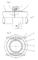
- FIG. 1:
- Pipe connection to a ceramic attachment in half section.
- FIG. 2:
- View A of FIG. 1.
- FIG. 3:
- Bolts.
- FIG. 4:
- Pipe with modified collar (connection side 2).
- FIG. 5:
- View B on FIG. 4.
- FIG. 6:
- O-ring.
- FIG. 7:
- View C of FIG. 8.
- FIG. 8:
- Half section through the first connection side with the annular limiting connecting part or the bell sleeve.
- FIG. 9:
- Pipe with groove on the holding surface.
Die Figur 1 zeigt zwei Rohre 1, 2 im Halbschnitt, wobei die erste Anschlußseite 1aa ein
ringförmig begrenzendes Teil 6 oder eine Glockenmuffe aufweist, in der oben und unten
Bohrungen 4 angeordnet sind, durch die Bolzen 3 ragen, die eine zweite Anschlußseite 2
lösbar mit der ersten Anschlußseite 1 verbinden, wobei die zweite Anschlußseite 2 einen
weiteren Außendurchmesser 12 aufweist. Beide Anschlußseiten 1, 2 weisen ebene Flächen
7 auf, die aneinander liegen, wobei ein O-Ring 5 beide Teile 1, 2 gegeneinander abdichtet.
Den erforderlichen Anpreßdruck für die Abdichtung wird über die Bolzen 3 realisiert. 1 shows two
Die Figur 2 zeigt die Ansicht A von Figur 1, aus der erkennbar ist, daß oben und unten
Bolzen 3 im ringförmig begrenzenden Teil 6 angeordnet sind, wobei die Bolzen 3 auf einer
Seite ein konisches Ende 8 aufweisen, um die Montage zu erleichtern. Figure 2 shows the view A of Figure 1, from which it can be seen that the top and
Die Figuren 4 und 5 zeigen die zweite Anschlußseite 2 für das Anschlußteil 9 in
verschiedenen Ansichten. Der an sich zylindrische Bund weist zwei Halteflächen 10 auf, die
um den Winkel α = 30° gegen die Planfläche 7 geneigt sind. Das anschließende Teil 9
(zweite Anschlußseite) besteht aus dem Werkstoff, der sich im Vergleich zur ersten
Anschlußseite leichter herstellen läßt. FIGS. 4 and 5 show the
Die Figur 3 zeigt den Bolzen 3 mit seinem konischen Ende 8. FIG. 3 shows the
Die Figur 6 zeigt den O-Ring 5 in Seitenansicht. FIG. 6 shows the O-
Die Figuren 7 und 8 zeigen die erste Anschlußseite mit ihrem ringförmigen oder
glockenförmigen Teil 6, durch das oben und unten die Bohrung 4 eingebracht ist, wobei in
der ebenen Fläche 7 die Nut 11 für den O-Ring 5 eingebracht wurde. Die Anschlußseite 1
mit der Glockenmuffe besteht aus einem Material, welches für aggressive und hoch
korrosive Medien besonders geeignet ist. Der Bolzen 3 sollte aus biegesteifem hoch
korrosionsbeständigem Material bestehen. Figures 7 and 8 show the first terminal side with its annular or bell-shaped
Die Figur 9 zeigt eine Ausführungsvariante, bei der die Haltefläche 10 mit einer Nut 12 zur
besseren Stabilisierung ausgeführt ist. FIG. 9 shows a variant in which the holding
Die vorgeschlagene Lösung hat den Vorteil, daß eine lösbare Verbindung für Rohre, die aus unterschiedlichem Material bestehen können, die äußerlich von aggressiven Medien umströmt und in denen aggressive Medien transportiert werden, auf schnelle und einfache Weise kostengünstig herstellbar ist und mit geringem Aufwand in der vorgegebenen Position montierbar ist. The proposed solution has the advantage that a detachable connection for pipes that out may consist of different materials that are externally from aggressive media flows around and in which aggressive media are transported, fast and easy Way is inexpensive to produce and with little effort in the predetermined position can be mounted.
- 1.1.
- Erste AnschlußseiteFirst connection side
- 2.Second
- Zweite AnschlußseiteSecond connection side
- 3.Third
- Bolzenbolt
- 4.4th
- Bohrung in 6Hole in 6
- 5.5th
- O-RingO-ring
- 6.6th
- Ringförmig begrenzendes Teil, GlockenmuffeRing-shaped limiting part, bell socket
- 7.7th
- Ebene Fläche an der Stirnseite von 1 oder 2Level area at the front of 1 or 2
- 8.8th.
- Konisches Ende des BolzensTapered end of the bolt
- 9.9th
- Anschlussteil (schwer zu bearbeitender Werkstoff)Connecting part (difficult to work material)
- 10.10th
- Haltefläche im Winkel α zu 7Holding surface at an angle α to 7
- 11.11th
- Nut in 7Groove in 7
- 12.12th
-
Nut der Haltefläche 10Groove of the holding
surface 10
Claims (8)
Priority Applications (1)
| Application Number | Priority Date | Filing Date | Title |
|---|---|---|---|
| PL04028777T PL1544531T3 (en) | 2003-12-20 | 2004-12-04 | Releasable tube coupling |
Applications Claiming Priority (2)
| Application Number | Priority Date | Filing Date | Title |
|---|---|---|---|
| DE20319819U | 2003-12-20 | ||
| DE20319819U DE20319819U1 (en) | 2003-12-20 | 2003-12-20 | Detachable connection for pipes, in particular for attachments to suspension distribution pipes within a flue gas scrubber |
Publications (2)
| Publication Number | Publication Date |
|---|---|
| EP1544531A1 true EP1544531A1 (en) | 2005-06-22 |
| EP1544531B1 EP1544531B1 (en) | 2006-09-06 |
Family
ID=32087666
Family Applications (1)
| Application Number | Title | Priority Date | Filing Date |
|---|---|---|---|
| EP04028777A Active EP1544531B1 (en) | 2003-12-20 | 2004-12-04 | Releasable tube coupling |
Country Status (5)
| Country | Link |
|---|---|
| EP (1) | EP1544531B1 (en) |
| CN (1) | CN100516617C (en) |
| AT (1) | ATE338910T1 (en) |
| DE (2) | DE20319819U1 (en) |
| PL (1) | PL1544531T3 (en) |
Cited By (3)
| Publication number | Priority date | Publication date | Assignee | Title |
|---|---|---|---|---|
| EP1818593A1 (en) * | 2006-02-13 | 2007-08-15 | Vaillant GmbH | Fastening part in connection with a pipeline |
| DE102007010659A1 (en) | 2007-03-02 | 2008-09-04 | Tpr Fiberdur Gmbh & Co. Kg | Detachable connection for connecting a connecting support of a spray nozzle of a waste gas scrubber to a connecting pipe comprises a flexible securing element partly following the curve of the inner surface of a sleeve-like end section |
| CN109132246A (en) * | 2018-08-30 | 2019-01-04 | 浙江德清科赛塑料制品有限公司 | Oil tank connector |
Families Citing this family (2)
| Publication number | Priority date | Publication date | Assignee | Title |
|---|---|---|---|---|
| ITMI20061372A1 (en) | 2006-07-14 | 2008-01-15 | Renato Colombo | RAPID CONNECTION DEVICE TO ACTIVATE THE CONNECTION BETWEEN A TUBE AND A COMPONENT IN PARTICULAR A COLLECTOR OR AN INTERCEPTION VALVE OF DISTRIBUTION PLANTS FOR LIQUIDS OR GASES |
| CN112263394A (en) * | 2020-09-27 | 2021-01-26 | 余丽红 | Double high-waist paper diaper comfortable to wear and capable of avoiding friction |
Citations (7)
| Publication number | Priority date | Publication date | Assignee | Title |
|---|---|---|---|---|
| FR2142147A5 (en) * | 1971-06-14 | 1973-01-26 | Sprunck Emile | |
| US4682472A (en) * | 1984-08-27 | 1987-07-28 | Tunzini Nessi Entreprises D'equipements | Coupling device for tubes, tubular elbows and end plates of thermoelectric devices |
| US4768587A (en) * | 1985-05-15 | 1988-09-06 | Suddeutsche Kuhlerfabrik Julius Fr. Behr Gmbh & Co. Kg | Pipe connection for heat exchangers |
| US5513882A (en) * | 1994-09-30 | 1996-05-07 | Lewis; Phil | Universal non-threaded pipe connector system |
| US6042154A (en) * | 1996-12-21 | 2000-03-28 | Daimlerchrysler Ag | Arrangement for joining tubular duct sections |
| EP1024324A2 (en) * | 1999-01-29 | 2000-08-02 | Renato Colombo | Device for mutually coupling the body of a valve element or the like and a connecting element |
| EP1209406A1 (en) * | 2000-11-23 | 2002-05-29 | Eaton Fluid Power GmbH | Quick-acting coupling device |
-
2003
- 2003-12-20 DE DE20319819U patent/DE20319819U1/en not_active Expired - Lifetime
-
2004
- 2004-12-04 PL PL04028777T patent/PL1544531T3/en unknown
- 2004-12-04 AT AT04028777T patent/ATE338910T1/en active
- 2004-12-04 DE DE502004001404T patent/DE502004001404D1/en active Active
- 2004-12-04 EP EP04028777A patent/EP1544531B1/en active Active
- 2004-12-20 CN CNB200410102129XA patent/CN100516617C/en active Active
Patent Citations (7)
| Publication number | Priority date | Publication date | Assignee | Title |
|---|---|---|---|---|
| FR2142147A5 (en) * | 1971-06-14 | 1973-01-26 | Sprunck Emile | |
| US4682472A (en) * | 1984-08-27 | 1987-07-28 | Tunzini Nessi Entreprises D'equipements | Coupling device for tubes, tubular elbows and end plates of thermoelectric devices |
| US4768587A (en) * | 1985-05-15 | 1988-09-06 | Suddeutsche Kuhlerfabrik Julius Fr. Behr Gmbh & Co. Kg | Pipe connection for heat exchangers |
| US5513882A (en) * | 1994-09-30 | 1996-05-07 | Lewis; Phil | Universal non-threaded pipe connector system |
| US6042154A (en) * | 1996-12-21 | 2000-03-28 | Daimlerchrysler Ag | Arrangement for joining tubular duct sections |
| EP1024324A2 (en) * | 1999-01-29 | 2000-08-02 | Renato Colombo | Device for mutually coupling the body of a valve element or the like and a connecting element |
| EP1209406A1 (en) * | 2000-11-23 | 2002-05-29 | Eaton Fluid Power GmbH | Quick-acting coupling device |
Cited By (4)
| Publication number | Priority date | Publication date | Assignee | Title |
|---|---|---|---|---|
| EP1818593A1 (en) * | 2006-02-13 | 2007-08-15 | Vaillant GmbH | Fastening part in connection with a pipeline |
| DE102007010659A1 (en) | 2007-03-02 | 2008-09-04 | Tpr Fiberdur Gmbh & Co. Kg | Detachable connection for connecting a connecting support of a spray nozzle of a waste gas scrubber to a connecting pipe comprises a flexible securing element partly following the curve of the inner surface of a sleeve-like end section |
| DE202007018993U1 (en) | 2007-03-02 | 2010-01-07 | Tpr Fiberdur Gmbh & Co. Kg | Detachable non-twist connection |
| CN109132246A (en) * | 2018-08-30 | 2019-01-04 | 浙江德清科赛塑料制品有限公司 | Oil tank connector |
Also Published As
| Publication number | Publication date |
|---|---|
| EP1544531B1 (en) | 2006-09-06 |
| CN100516617C (en) | 2009-07-22 |
| DE20319819U1 (en) | 2004-04-01 |
| ATE338910T1 (en) | 2006-09-15 |
| PL1544531T3 (en) | 2007-01-31 |
| CN1644973A (en) | 2005-07-27 |
| DE502004001404D1 (en) | 2006-10-19 |
Similar Documents
| Publication | Publication Date | Title |
|---|---|---|
| DE3443943A1 (en) | Pipe connection | |
| EP0073048A1 (en) | Device for connecting a plastics pipe to a pipe socket | |
| DE3741250A1 (en) | DEVICE FOR INTERMEDIALLY CONNECTING TWO PIPES, IN PARTICULAR FUEL PIPES | |
| EP1544531B1 (en) | Releasable tube coupling | |
| DE202020103581U1 (en) | Flange connection arrangement for a pipeline | |
| EP1647507B1 (en) | Device for conveying solid materials in a pipe | |
| EP0073050B1 (en) | Clamping connections for even circular bodies, especially pipes and rods | |
| DE3416109A1 (en) | Device for the pivotable and detachable connection of two pipelines which run at an angle with respect to one another | |
| DE3221518C2 (en) | Fittings for the automatic connection of lines in pneumatic or hydraulic circuits | |
| DE3911258C2 (en) | ||
| DE4009403C2 (en) | Pipe coupling | |
| DE2846755C3 (en) | Swivel joint | |
| CH398217A (en) | Pressure-tight coupling between pipe and hose lines | |
| DE3110923A1 (en) | Domestic gas connecting device | |
| DE202009018707U1 (en) | Pipe connection system | |
| CH657436A5 (en) | SCREWING SYSTEM. | |
| EP0288993A1 (en) | Device for joining the coaxial ends of two pipes without mandrels together | |
| DE10234015B4 (en) | flange | |
| DE10158983A1 (en) | Socket connection for end of pipe has spherical joint with sealing ring to enable two pipes to be connected together at angle | |
| WO1992002753A1 (en) | Connector for linear b1/b2 pipe sections for the conveyance of gases or liquids | |
| DE2456166A1 (en) | Detachably connecting flexible plastic pipes - having inner connecting sleeve and outer sleeve segments with bolts engaging inner sleeve | |
| DE2545518A1 (en) | Underwater pipeline coupling - has welded hald and moving half with internal taper for cone insert and seal rings compression | |
| DE102022108544A1 (en) | Repair set and method for repairing pipelines of a system for transporting solids and fluids | |
| EP0534042A1 (en) | Angle insert assembly for pressure fluid hoses | |
| DE102009021339B4 (en) | Media line with at least one pipe section and at least one coupling element |
Legal Events
| Date | Code | Title | Description |
|---|---|---|---|
| PUAI | Public reference made under article 153(3) epc to a published international application that has entered the european phase |
Free format text: ORIGINAL CODE: 0009012 |
|
| AK | Designated contracting states |
Kind code of ref document: A1 Designated state(s): AT BE BG CH CY CZ DE DK EE ES FI FR GB GR HU IE IS IT LI LT LU MC NL PL PT RO SE SI SK TR |
|
| AX | Request for extension of the european patent |
Extension state: AL BA HR LV MK YU |
|
| 17P | Request for examination filed |
Effective date: 20051001 |
|
| AKX | Designation fees paid |
Designated state(s): AT BE BG CH CY CZ DE DK EE ES FI FR GB GR HU IE IS IT LI LT LU MC NL PL PT RO SE SI SK TR |
|
| GRAP | Despatch of communication of intention to grant a patent |
Free format text: ORIGINAL CODE: EPIDOSNIGR1 |
|
| GRAS | Grant fee paid |
Free format text: ORIGINAL CODE: EPIDOSNIGR3 |
|
| GRAA | (expected) grant |
Free format text: ORIGINAL CODE: 0009210 |
|
| AK | Designated contracting states |
Kind code of ref document: B1 Designated state(s): AT BE BG CH CY CZ DE DK EE ES FI FR GB GR HU IE IS IT LI LT LU MC NL PL PT RO SE SI SK TR |
|
| PG25 | Lapsed in a contracting state [announced via postgrant information from national office to epo] |
Ref country code: GB Free format text: LAPSE BECAUSE OF FAILURE TO SUBMIT A TRANSLATION OF THE DESCRIPTION OR TO PAY THE FEE WITHIN THE PRESCRIBED TIME-LIMIT Effective date: 20060906 Ref country code: RO Free format text: LAPSE BECAUSE OF FAILURE TO SUBMIT A TRANSLATION OF THE DESCRIPTION OR TO PAY THE FEE WITHIN THE PRESCRIBED TIME-LIMIT Effective date: 20060906 Ref country code: LT Free format text: LAPSE BECAUSE OF FAILURE TO SUBMIT A TRANSLATION OF THE DESCRIPTION OR TO PAY THE FEE WITHIN THE PRESCRIBED TIME-LIMIT Effective date: 20060906 Ref country code: IE Free format text: LAPSE BECAUSE OF FAILURE TO SUBMIT A TRANSLATION OF THE DESCRIPTION OR TO PAY THE FEE WITHIN THE PRESCRIBED TIME-LIMIT Effective date: 20060906 Ref country code: CZ Free format text: LAPSE BECAUSE OF FAILURE TO SUBMIT A TRANSLATION OF THE DESCRIPTION OR TO PAY THE FEE WITHIN THE PRESCRIBED TIME-LIMIT Effective date: 20060906 Ref country code: FI Free format text: LAPSE BECAUSE OF FAILURE TO SUBMIT A TRANSLATION OF THE DESCRIPTION OR TO PAY THE FEE WITHIN THE PRESCRIBED TIME-LIMIT Effective date: 20060906 Ref country code: SI Free format text: LAPSE BECAUSE OF FAILURE TO SUBMIT A TRANSLATION OF THE DESCRIPTION OR TO PAY THE FEE WITHIN THE PRESCRIBED TIME-LIMIT Effective date: 20060906 Ref country code: SK Free format text: LAPSE BECAUSE OF FAILURE TO SUBMIT A TRANSLATION OF THE DESCRIPTION OR TO PAY THE FEE WITHIN THE PRESCRIBED TIME-LIMIT Effective date: 20060906 |
|
| REG | Reference to a national code |
Ref country code: GB Ref legal event code: FG4D Free format text: NOT ENGLISH |
|
| REG | Reference to a national code |
Ref country code: CH Ref legal event code: EP |
|
| REG | Reference to a national code |
Ref country code: IE Ref legal event code: FG4D Free format text: LANGUAGE OF EP DOCUMENT: GERMAN |
|
| REF | Corresponds to: |
Ref document number: 502004001404 Country of ref document: DE Date of ref document: 20061019 Kind code of ref document: P |
|
| PG25 | Lapsed in a contracting state [announced via postgrant information from national office to epo] |
Ref country code: SE Free format text: LAPSE BECAUSE OF FAILURE TO SUBMIT A TRANSLATION OF THE DESCRIPTION OR TO PAY THE FEE WITHIN THE PRESCRIBED TIME-LIMIT Effective date: 20061206 Ref country code: DK Free format text: LAPSE BECAUSE OF FAILURE TO SUBMIT A TRANSLATION OF THE DESCRIPTION OR TO PAY THE FEE WITHIN THE PRESCRIBED TIME-LIMIT Effective date: 20061206 Ref country code: BG Free format text: LAPSE BECAUSE OF FAILURE TO SUBMIT A TRANSLATION OF THE DESCRIPTION OR TO PAY THE FEE WITHIN THE PRESCRIBED TIME-LIMIT Effective date: 20061206 |
|
| PG25 | Lapsed in a contracting state [announced via postgrant information from national office to epo] |
Ref country code: ES Free format text: LAPSE BECAUSE OF FAILURE TO SUBMIT A TRANSLATION OF THE DESCRIPTION OR TO PAY THE FEE WITHIN THE PRESCRIBED TIME-LIMIT Effective date: 20061217 |
|
| PG25 | Lapsed in a contracting state [announced via postgrant information from national office to epo] |
Ref country code: BE Free format text: LAPSE BECAUSE OF NON-PAYMENT OF DUE FEES Effective date: 20061231 Ref country code: MC Free format text: LAPSE BECAUSE OF NON-PAYMENT OF DUE FEES Effective date: 20061231 |
|
| PG25 | Lapsed in a contracting state [announced via postgrant information from national office to epo] |
Ref country code: IS Free format text: LAPSE BECAUSE OF FAILURE TO SUBMIT A TRANSLATION OF THE DESCRIPTION OR TO PAY THE FEE WITHIN THE PRESCRIBED TIME-LIMIT Effective date: 20070106 |
|
| REG | Reference to a national code |
Ref country code: PL Ref legal event code: T3 |
|
| PG25 | Lapsed in a contracting state [announced via postgrant information from national office to epo] |
Ref country code: PT Free format text: LAPSE BECAUSE OF FAILURE TO SUBMIT A TRANSLATION OF THE DESCRIPTION OR TO PAY THE FEE WITHIN THE PRESCRIBED TIME-LIMIT Effective date: 20070219 |
|
| GBV | Gb: ep patent (uk) treated as always having been void in accordance with gb section 77(7)/1977 [no translation filed] |
Effective date: 20060906 |
|
| REG | Reference to a national code |
Ref country code: IE Ref legal event code: FD4D |
|
| EN | Fr: translation not filed | ||
| PLBE | No opposition filed within time limit |
Free format text: ORIGINAL CODE: 0009261 |
|
| STAA | Information on the status of an ep patent application or granted ep patent |
Free format text: STATUS: NO OPPOSITION FILED WITHIN TIME LIMIT |
|
| 26N | No opposition filed |
Effective date: 20070607 |
|
| BERE | Be: lapsed |
Owner name: FISIA BABCOCK ENVIRONMENT G.M.B.H. Effective date: 20061231 |
|
| PG25 | Lapsed in a contracting state [announced via postgrant information from national office to epo] |
Ref country code: GR Free format text: LAPSE BECAUSE OF FAILURE TO SUBMIT A TRANSLATION OF THE DESCRIPTION OR TO PAY THE FEE WITHIN THE PRESCRIBED TIME-LIMIT Effective date: 20061207 Ref country code: FR Free format text: LAPSE BECAUSE OF FAILURE TO SUBMIT A TRANSLATION OF THE DESCRIPTION OR TO PAY THE FEE WITHIN THE PRESCRIBED TIME-LIMIT Effective date: 20070511 |
|
| PG25 | Lapsed in a contracting state [announced via postgrant information from national office to epo] |
Ref country code: EE Free format text: LAPSE BECAUSE OF FAILURE TO SUBMIT A TRANSLATION OF THE DESCRIPTION OR TO PAY THE FEE WITHIN THE PRESCRIBED TIME-LIMIT Effective date: 20060906 |
|
| PG25 | Lapsed in a contracting state [announced via postgrant information from national office to epo] |
Ref country code: TR Free format text: LAPSE BECAUSE OF FAILURE TO SUBMIT A TRANSLATION OF THE DESCRIPTION OR TO PAY THE FEE WITHIN THE PRESCRIBED TIME-LIMIT Effective date: 20060906 Ref country code: HU Free format text: LAPSE BECAUSE OF FAILURE TO SUBMIT A TRANSLATION OF THE DESCRIPTION OR TO PAY THE FEE WITHIN THE PRESCRIBED TIME-LIMIT Effective date: 20070307 Ref country code: LU Free format text: LAPSE BECAUSE OF NON-PAYMENT OF DUE FEES Effective date: 20061204 |
|
| PG25 | Lapsed in a contracting state [announced via postgrant information from national office to epo] |
Ref country code: FR Free format text: LAPSE BECAUSE OF FAILURE TO SUBMIT A TRANSLATION OF THE DESCRIPTION OR TO PAY THE FEE WITHIN THE PRESCRIBED TIME-LIMIT Effective date: 20060906 Ref country code: CY Free format text: LAPSE BECAUSE OF FAILURE TO SUBMIT A TRANSLATION OF THE DESCRIPTION OR TO PAY THE FEE WITHIN THE PRESCRIBED TIME-LIMIT Effective date: 20060906 |
|
| REG | Reference to a national code |
Ref country code: CH Ref legal event code: PL |
|
| PG25 | Lapsed in a contracting state [announced via postgrant information from national office to epo] |
Ref country code: CH Free format text: LAPSE BECAUSE OF NON-PAYMENT OF DUE FEES Effective date: 20081231 Ref country code: LI Free format text: LAPSE BECAUSE OF NON-PAYMENT OF DUE FEES Effective date: 20081231 |
|
| REG | Reference to a national code |
Ref country code: DE Ref legal event code: R082 Ref document number: 502004001404 Country of ref document: DE Representative=s name: LUEDTKE, FRANK, DIPL.-ING., DE Ref country code: DE Ref legal event code: R081 Ref document number: 502004001404 Country of ref document: DE Owner name: STEINMUELLER BABCOCK ENVIRONMENT GMBH, DE Free format text: FORMER OWNER: FISIA BABCOCK ENVIRONMENT GMBH, 51643 GUMMERSBACH, DE Ref country code: DE Ref legal event code: R081 Ref document number: 502004001404 Country of ref document: DE Owner name: NIPPON STEEL & SUMIKIN ENGINEERING CO., LTD., JP Free format text: FORMER OWNER: FISIA BABCOCK ENVIRONMENT GMBH, 51643 GUMMERSBACH, DE |
|
| REG | Reference to a national code |
Ref country code: NL Ref legal event code: TD Effective date: 20150702 |
|
| REG | Reference to a national code |
Ref country code: DE Ref legal event code: R081 Ref document number: 502004001404 Country of ref document: DE Owner name: HITACHI ZOSEN INOVA STEINMUELLER GMBH, DE Free format text: FORMER OWNER: STEINMUELLER BABCOCK ENVIRONMENT GMBH, 51643 GUMMERSBACH, DE Ref country code: DE Ref legal event code: R082 Ref document number: 502004001404 Country of ref document: DE Representative=s name: LUEDTKE, FRANK, DIPL.-ING., DE Ref country code: DE Ref legal event code: R081 Ref document number: 502004001404 Country of ref document: DE Owner name: STEINMUELLER BABCOCK ENVIRONMENT GMBH, DE Free format text: FORMER OWNER: STEINMUELLER BABCOCK ENVIRONMENT GMBH, 51643 GUMMERSBACH, DE Ref country code: DE Ref legal event code: R081 Ref document number: 502004001404 Country of ref document: DE Owner name: NIPPON STEEL & SUMIKIN ENGINEERING CO., LTD., JP Free format text: FORMER OWNER: STEINMUELLER BABCOCK ENVIRONMENT GMBH, 51643 GUMMERSBACH, DE |
|
| REG | Reference to a national code |
Ref country code: NL Ref legal event code: PD Owner name: NIPPON STEEL & SUMIKIN ENGINEERING CO., LTD.; JP Free format text: DETAILS ASSIGNMENT: CHANGE OF OWNER(S), ASSIGNMENT; FORMER OWNER NAME: STEINMUELLER BABCOCK ENVIRONMENT GMBH Effective date: 20181214 |
|
| REG | Reference to a national code |
Ref country code: AT Ref legal event code: PC Ref document number: 338910 Country of ref document: AT Kind code of ref document: T Owner name: STEINMUELLER BABCOCK ENVIRONMENT GMBH, DE Effective date: 20190307 Ref country code: AT Ref legal event code: PC Ref document number: 338910 Country of ref document: AT Kind code of ref document: T Owner name: NIPPON STEEL & SUMIKIN ENGINEERING CO., LTD., JP Effective date: 20190307 |
|
| REG | Reference to a national code |
Ref country code: DE Ref legal event code: R081 Ref document number: 502004001404 Country of ref document: DE Owner name: HITACHI ZOSEN INOVA STEINMUELLER GMBH, DE Free format text: FORMER OWNERS: NIPPON STEEL & SUMIKIN ENGINEERING CO., LTD., TOKYO, JP; STEINMUELLER BABCOCK ENVIRONMENT GMBH, 51643 GUMMERSBACH, DE |
|
| REG | Reference to a national code |
Ref country code: NL Ref legal event code: PD Owner name: HITACHI ZOSEN INOVA STEINMUELLER GMBH; DE Free format text: DETAILS ASSIGNMENT: CHANGE OF OWNER(S), ASSIGNMENT; FORMER OWNER NAME: STEINMUELLER BABCOCK ENVIRONMENT GMBH Effective date: 20220830 Ref country code: NL Ref legal event code: HC Owner name: NIPPON STEEL ENGINEERING CO., LTD.; JP Free format text: DETAILS ASSIGNMENT: CHANGE OF OWNER(S), CHANGE OF OWNER(S) NAME; FORMER OWNER NAME: STEINMUELLER BABCOCK ENVIRONMENT GMBH Effective date: 20220830 |
|
| REG | Reference to a national code |
Ref country code: AT Ref legal event code: PC Ref document number: 338910 Country of ref document: AT Kind code of ref document: T Owner name: HITACHI ZOSEN INOVA STEINMUELLER GMBH, DE Effective date: 20221018 |
|
| PGFP | Annual fee paid to national office [announced via postgrant information from national office to epo] |
Ref country code: PL Payment date: 20221118 Year of fee payment: 19 |
|
| PGFP | Annual fee paid to national office [announced via postgrant information from national office to epo] |
Ref country code: IT Payment date: 20221230 Year of fee payment: 19 Ref country code: DE Payment date: 20230210 Year of fee payment: 19 |
|
| PGFP | Annual fee paid to national office [announced via postgrant information from national office to epo] |
Ref country code: NL Payment date: 20231219 Year of fee payment: 20 Ref country code: AT Payment date: 20231214 Year of fee payment: 20 |
|
| PGFP | Annual fee paid to national office [announced via postgrant information from national office to epo] |
Ref country code: PL Payment date: 20231122 Year of fee payment: 20 |