EP1544489A1 - Demontierbares Kreuzgelenk für eine Kraftfahrzeug- Lenksäulenanordnung - Google Patents
Demontierbares Kreuzgelenk für eine Kraftfahrzeug- Lenksäulenanordnung Download PDFInfo
- Publication number
- EP1544489A1 EP1544489A1 EP04292837A EP04292837A EP1544489A1 EP 1544489 A1 EP1544489 A1 EP 1544489A1 EP 04292837 A EP04292837 A EP 04292837A EP 04292837 A EP04292837 A EP 04292837A EP 1544489 A1 EP1544489 A1 EP 1544489A1
- Authority
- EP
- European Patent Office
- Prior art keywords
- connecting element
- clamping
- axis
- fork
- jaw according
- Prior art date
- Legal status (The legal status is an assumption and is not a legal conclusion. Google has not performed a legal analysis and makes no representation as to the accuracy of the status listed.)
- Granted
Links
- 230000005540 biological transmission Effects 0.000 claims abstract description 27
- 239000002184 metal Substances 0.000 claims description 3
- 230000000903 blocking effect Effects 0.000 description 2
- 241000239290 Araneae Species 0.000 description 1
- 239000011324 bead Substances 0.000 description 1
- 238000005242 forging Methods 0.000 description 1
- 238000012423 maintenance Methods 0.000 description 1
- 238000004519 manufacturing process Methods 0.000 description 1
Images


Classifications
-
- B—PERFORMING OPERATIONS; TRANSPORTING
- B62—LAND VEHICLES FOR TRAVELLING OTHERWISE THAN ON RAILS
- B62D—MOTOR VEHICLES; TRAILERS
- B62D1/00—Steering controls, i.e. means for initiating a change of direction of the vehicle
- B62D1/02—Steering controls, i.e. means for initiating a change of direction of the vehicle vehicle-mounted
- B62D1/16—Steering columns
- B62D1/20—Connecting steering column to steering gear
-
- F—MECHANICAL ENGINEERING; LIGHTING; HEATING; WEAPONS; BLASTING
- F16—ENGINEERING ELEMENTS AND UNITS; GENERAL MEASURES FOR PRODUCING AND MAINTAINING EFFECTIVE FUNCTIONING OF MACHINES OR INSTALLATIONS; THERMAL INSULATION IN GENERAL
- F16D—COUPLINGS FOR TRANSMITTING ROTATION; CLUTCHES; BRAKES
- F16D1/00—Couplings for rigidly connecting two coaxial shafts or other movable machine elements
- F16D1/06—Couplings for rigidly connecting two coaxial shafts or other movable machine elements for attachment of a member on a shaft or on a shaft-end
- F16D1/08—Couplings for rigidly connecting two coaxial shafts or other movable machine elements for attachment of a member on a shaft or on a shaft-end with clamping hub; with hub and longitudinal key
- F16D1/0852—Couplings for rigidly connecting two coaxial shafts or other movable machine elements for attachment of a member on a shaft or on a shaft-end with clamping hub; with hub and longitudinal key with radial clamping between the mating surfaces of the hub and shaft
- F16D1/0864—Couplings for rigidly connecting two coaxial shafts or other movable machine elements for attachment of a member on a shaft or on a shaft-end with clamping hub; with hub and longitudinal key with radial clamping between the mating surfaces of the hub and shaft due to tangential loading of the hub, e.g. a split hub
-
- F—MECHANICAL ENGINEERING; LIGHTING; HEATING; WEAPONS; BLASTING
- F16—ENGINEERING ELEMENTS AND UNITS; GENERAL MEASURES FOR PRODUCING AND MAINTAINING EFFECTIVE FUNCTIONING OF MACHINES OR INSTALLATIONS; THERMAL INSULATION IN GENERAL
- F16D—COUPLINGS FOR TRANSMITTING ROTATION; CLUTCHES; BRAKES
- F16D1/00—Couplings for rigidly connecting two coaxial shafts or other movable machine elements
- F16D1/12—Couplings for rigidly connecting two coaxial shafts or other movable machine elements allowing adjustment of the parts about the axis
-
- F—MECHANICAL ENGINEERING; LIGHTING; HEATING; WEAPONS; BLASTING
- F16—ENGINEERING ELEMENTS AND UNITS; GENERAL MEASURES FOR PRODUCING AND MAINTAINING EFFECTIVE FUNCTIONING OF MACHINES OR INSTALLATIONS; THERMAL INSULATION IN GENERAL
- F16D—COUPLINGS FOR TRANSMITTING ROTATION; CLUTCHES; BRAKES
- F16D3/00—Yielding couplings, i.e. with means permitting movement between the connected parts during the drive
- F16D3/16—Universal joints in which flexibility is produced by means of pivots or sliding or rolling connecting parts
- F16D3/26—Hooke's joints or other joints with an equivalent intermediate member to which each coupling part is pivotally or slidably connected
- F16D3/38—Hooke's joints or other joints with an equivalent intermediate member to which each coupling part is pivotally or slidably connected with a single intermediate member with trunnions or bearings arranged on two axes perpendicular to one another
- F16D3/382—Hooke's joints or other joints with an equivalent intermediate member to which each coupling part is pivotally or slidably connected with a single intermediate member with trunnions or bearings arranged on two axes perpendicular to one another constructional details of other than the intermediate member
- F16D3/387—Fork construction; Mounting of fork on shaft; Adapting shaft for mounting of fork
-
- F—MECHANICAL ENGINEERING; LIGHTING; HEATING; WEAPONS; BLASTING
- F16—ENGINEERING ELEMENTS AND UNITS; GENERAL MEASURES FOR PRODUCING AND MAINTAINING EFFECTIVE FUNCTIONING OF MACHINES OR INSTALLATIONS; THERMAL INSULATION IN GENERAL
- F16D—COUPLINGS FOR TRANSMITTING ROTATION; CLUTCHES; BRAKES
- F16D1/00—Couplings for rigidly connecting two coaxial shafts or other movable machine elements
- F16D1/10—Quick-acting couplings in which the parts are connected by simply bringing them together axially
- F16D2001/103—Quick-acting couplings in which the parts are connected by simply bringing them together axially the torque is transmitted via splined connections
Definitions
- the current steering column of a vehicle car has two portions: a high portion which is connected to the steering wheel, and a portion intermediate that is connected to the steering box commanding a steering rod of the wheels guidelines.
- the upper portion and the portion intermediary are connected to each other by a constant velocity joint called universal joint.
- said universal joint includes a spider disposed between two jaws, one of which is connected to the portion high and whose other is connected to the portion intermediate.
- Known universal joints include jaws that consist of a single element piece.
- the clamping system the jaw of cardan on the shaft of transmission corresponding, has an axis that has an orientation determined with respect to the axis of articulation of the jaw.
- the purpose of the present invention is to propose a gimbal jaw, especially for a column of motor vehicle management, which avoids disadvantages described above, in order to have a gimbal jaw that can adapt to all types of vehicle.
- the universal joint jaw consists of a alone and together, the combined forms of the outer face and inner face are dimensioned in order to get some tightness between the cylindrical portion and the cylindrical end, and to obtain the means of axial connection between the connecting element and the fork hinge.
- the conjugate forms of the outer face and the inner face consist of splines.
- the forms conjugate of the outer and inner sides consist of serrations.
- the clamping system of the universal joint jaw of the invention is that the element of connection to a clamping portion, which comprises a cylindrical element with two clamping elements.
- the two clamping elements are separated by a axial opening opening into an inner face of the cylindrical element, the clamping axis being substantially perpendicular to said opening axial.
- a tangential groove cross-section is arranged on the cylindrical portion, and next to the clamping elements.
- the means clamping consist of a clamping screw.
- the connecting element of the gimbal jaw has internal faces, which have shapes conjugate with the drive shaft to ensure the connection in rotation.
- the conjugate forms of the internal faces of the element connection shaft and drive shaft consist in grooves.
- the universal joint jaw has the element of connection, which consists of a forging and machined.
- the connecting element is constituted by a piece machined sheet metal.
- the connecting element consists of a cut and machined stretched piece.
- the universal joint jaw according to the present invention so the benefit of offering a set, which is made from a hinge fork, which can be standard, with a connection element, which can also be standard.
- This allows mass production with a higher cost low.
- a decisive advantage of the invention is to allow an orientation of the connection element with respect to the fork of articulation, so that the jaw of cardan fits each type of vehicle with a mounting more accessible and easier.
- the universal joint jaw according to the invention is on a motion transmission shaft 5 shown in axial section in FIGS. 5 and 6, and having an axis 6.
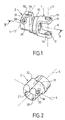
- the jaw is detachable and it includes a hinge fork 1 and an element of connection 2.
- the hinge fork 1 is connected to a other articulation fork, via a brace to form the seal of gimbal.
- the hinge fork 1 comprises an axis articulation 3 which is also one of the two axes of the transept.
- the connecting element 2 is mounted on the shaft motion transmission 5, and is blocked by a clamping system, which is arranged on said element connection, which includes the clamping pin 4.
- the hinge fork 1 is mounted on connecting element 2 in order to constitute the jaw of cardan.
- the articulation fork 1 and the connecting element 2 have the same axis, which is the axis 6 of the motion transmission shaft 5.
- angular positioning means are arranged between the connecting element 2 carrying the clamping axis 4 and the hinge fork 1 which has the hinge axis 3.
- connection means in rotation and axial connection means are provided between the connecting element 2 and the fork articulation 1, which thus form a same set.
- the hinge fork 1 has a cylindrical end 10 of axis 6, which is provided with two arms 11 and 12.
- Each arm 11 and 12 has a hole corresponding hinge 13 and 14.
- the holes 13 and 14 are aligned along the axis articulation 3.
- the cylindrical end 10 has a face internal cylindrical 15 and a bearing surface 16 perpendicular to the transmission axis 6.
- the connecting element 2 represented on the Figures 1 to 4 and more specifically in Figures 5 and 6, is constituted by a cylindrical portion 20 and a clamping portion 21.
- the portion of tightening 21 is arranged in the extension of the cylindrical portion 20.
- the cylindrical portion 20 has a face 22 cylindrical external axis 6 and a bearing face 25 perpendicular to the transmission axis 6.
- the clamping portion 21 has an element cylindrical 30 and two clamping members 31 and 32.
- the cylindrical element 30 is an extension of the cylindrical portion 20, with the same axis 6.
- the cylindrical element 30 and the cylindrical portion 20 have the same internal face 27 which is cylindrical and mounts on the drive shaft 5. Both clamping elements 31 and 32 are separated by a axial opening 35, which opens into the face 27.
- the clamping axis 4 is embodied by a hole 33 of the clamping member 31 and a hole 34 of the clamping member 32, the holes 33 and 34 being aligned.
- the hole 33 is a passage hole of a screw tightening, which engages in the threaded hole 34 and apply against a support face 36 arranged outside the clamping member 31.
- the axis of tightening 4 is perpendicular to the axial opening 35.
- a transverse tangential groove 26 is arranged on the cylindrical portion 20.
- the groove tangential 26 is arranged next to the elements of clamping 31 and 32, so that said elements of have the flexibility to allow the blocking.
- the connecting element 2 is mounted in the articulated fork 1, engaging the portion cylindrical 20 in the cylindrical end 10, until the bearing face 25 is applied against the bearing face 16.
- the outer face 2 cooperates with the inner face 15, having conjugate shapes for to have the desired orientation between the element of connection 2 and the articulation fork 1, and thus obtain the means of angular positioning and the rotation connection means.
- the conjugate forms of the face outer 22 and the inner face 15 are sized to get a certain amount of tightness between the cylindrical portion 20 and the cylindrical end 10. That provision ensures the maintenance of connection in rotation, and allows to obtain the means axial connection between the connecting element 2 and the hinge fork 1.
- the conjugate forms consist of grooves 23 made on the face external 22, which cooperate with splines 17 performed on the inner face 15.
- the conjugate forms consist of serrations 24 made on the face 22, which cooperate with serrations 18 performed on the inner face 15.
- the cylindrical portion 20 and the portion of tightening 21 of the connecting element 2 have internal faces 27, which have shapes conjugated with the transmission shaft 5 to ensure the connection in rotation of the universal joint jaw with said shaft transmission 5.
- the conjugated forms consist of splines 28 made on the internal faces 27 which cooperate with splines 7 performed on the drive shaft 5.
- Blocking is ensured by the clamping screw 9, which brings the two clamping elements 31 and 32 closer together.
- the connecting element 2 can be obtained from several ways.
- connection 2 consists of a sheet metal part stamped with a weld bead along the cylindrical portion 20, said part being then machined.
- connection 2 is constituted by a forged part and machined.
- the connecting element 2 is constituted by a cut and machined stretch part.
Landscapes
- Engineering & Computer Science (AREA)
- General Engineering & Computer Science (AREA)
- Mechanical Engineering (AREA)
- Chemical & Material Sciences (AREA)
- Combustion & Propulsion (AREA)
- Transportation (AREA)
- Steering Controls (AREA)
- Clamps And Clips (AREA)
- Mechanical Operated Clutches (AREA)
- Forklifts And Lifting Vehicles (AREA)
- Shafts, Cranks, Connecting Bars, And Related Bearings (AREA)
- Fittings On The Vehicle Exterior For Carrying Loads, And Devices For Holding Or Mounting Articles (AREA)
Applications Claiming Priority (2)
| Application Number | Priority Date | Filing Date | Title |
|---|---|---|---|
| FR0314846 | 2003-12-16 | ||
| FR0314846A FR2863674B1 (fr) | 2003-12-16 | 2003-12-16 | Machoire de cardan demontable d'une colonne de direction de vehicule automobile |
Publications (2)
| Publication Number | Publication Date |
|---|---|
| EP1544489A1 true EP1544489A1 (de) | 2005-06-22 |
| EP1544489B1 EP1544489B1 (de) | 2006-08-16 |
Family
ID=34508688
Family Applications (1)
| Application Number | Title | Priority Date | Filing Date |
|---|---|---|---|
| EP04292837A Expired - Lifetime EP1544489B1 (de) | 2003-12-16 | 2004-11-30 | Demontierbares Kreuzgelenk für eine Kraftfahrzeug- Lenksäulenanordnung |
Country Status (7)
| Country | Link |
|---|---|
| US (1) | US20050140130A1 (de) |
| EP (1) | EP1544489B1 (de) |
| JP (1) | JP3982534B2 (de) |
| AT (1) | ATE336669T1 (de) |
| BR (1) | BRPI0405337A (de) |
| DE (1) | DE602004001966T2 (de) |
| FR (1) | FR2863674B1 (de) |
Cited By (2)
| Publication number | Priority date | Publication date | Assignee | Title |
|---|---|---|---|---|
| WO2007092764A1 (en) * | 2006-02-03 | 2007-08-16 | Drivesol Worldwide, Inc. | Assembly aid for a steering column |
| DE102011050748B3 (de) * | 2011-05-31 | 2012-07-12 | Thyssenkrupp Presta Aktiengesellschaft | Verbindung eines Wellenstücks einer Lenkwelle für ein Kraftfahrzeug mit einem Anschlussteil |
Families Citing this family (7)
| Publication number | Priority date | Publication date | Assignee | Title |
|---|---|---|---|---|
| US20080211217A1 (en) * | 2007-03-02 | 2008-09-04 | Textron Inc. | Adjustable Steering System |
| JP5176349B2 (ja) * | 2007-03-15 | 2013-04-03 | 日本精工株式会社 | ステアリング装置 |
| DE102014209731B4 (de) * | 2013-08-09 | 2016-01-07 | Ford Global Technologies, Llc | Lenkung und Kraftfahrzeug |
| JP6179765B2 (ja) * | 2013-10-30 | 2017-08-16 | 株式会社ジェイテクト | 中間シャフト及び中間シャフトの製造方法並びに電動パワーステアリング装置。 |
| WO2015174432A1 (ja) * | 2014-05-13 | 2015-11-19 | 日本精工株式会社 | 十字軸式自在継手用ヨーク及びその製造方法 |
| US12110927B2 (en) | 2019-01-23 | 2024-10-08 | Nsk Ltd. | Torque transmission shaft |
| CN217197641U (zh) * | 2022-01-30 | 2022-08-16 | 炎展科技(上海)有限公司 | 分体式硬前桥及具有其的车辆 |
Citations (4)
| Publication number | Priority date | Publication date | Assignee | Title |
|---|---|---|---|---|
| EP0292442A1 (de) * | 1987-05-19 | 1988-11-23 | FIAT AUTO S.p.A. | Vorrichtung zum Positionieren der unteren Lenkwelle auf dem Zahnrad des Lenkgetriebes und auf der oberen Welle |
| EP0727340A1 (de) * | 1995-02-14 | 1996-08-21 | Ecia - Equipements Et Composants Pour L'industrie Automobile | Vorrichtung zur Montage eines Kraftfahrzeuglenkrads auf eine Lenksäule |
| GB2312034A (en) * | 1996-04-13 | 1997-10-15 | Delphi France Automotive Sys | Yoke assembly for a universal joint |
| EP1247719A2 (de) * | 2001-04-03 | 2002-10-09 | Delphi Technologies, Inc. | Zwischenrohr für eine Kraftfahrzeuglenksäule |
Family Cites Families (4)
| Publication number | Priority date | Publication date | Assignee | Title |
|---|---|---|---|---|
| JP2534772B2 (ja) * | 1989-07-07 | 1996-09-18 | 日本精工株式会社 | 自在継手のヨ−クの製造方法 |
| US5366316A (en) * | 1992-06-02 | 1994-11-22 | General Motors Corporation | Intermediate steering shaft assembly and method |
| US5628578A (en) * | 1995-07-28 | 1997-05-13 | Dana Corporation | Alternate pinch bolt yoke construction |
| JP3646556B2 (ja) * | 1998-06-11 | 2005-05-11 | 日本精工株式会社 | 弾性軸継手 |
-
2003
- 2003-12-16 FR FR0314846A patent/FR2863674B1/fr not_active Expired - Lifetime
-
2004
- 2004-11-29 BR BR0405337-0A patent/BRPI0405337A/pt not_active Application Discontinuation
- 2004-11-30 DE DE602004001966T patent/DE602004001966T2/de not_active Expired - Lifetime
- 2004-11-30 EP EP04292837A patent/EP1544489B1/de not_active Expired - Lifetime
- 2004-11-30 AT AT04292837T patent/ATE336669T1/de not_active IP Right Cessation
- 2004-12-13 US US11/009,089 patent/US20050140130A1/en not_active Abandoned
- 2004-12-15 JP JP2004362772A patent/JP3982534B2/ja not_active Expired - Fee Related
Patent Citations (4)
| Publication number | Priority date | Publication date | Assignee | Title |
|---|---|---|---|---|
| EP0292442A1 (de) * | 1987-05-19 | 1988-11-23 | FIAT AUTO S.p.A. | Vorrichtung zum Positionieren der unteren Lenkwelle auf dem Zahnrad des Lenkgetriebes und auf der oberen Welle |
| EP0727340A1 (de) * | 1995-02-14 | 1996-08-21 | Ecia - Equipements Et Composants Pour L'industrie Automobile | Vorrichtung zur Montage eines Kraftfahrzeuglenkrads auf eine Lenksäule |
| GB2312034A (en) * | 1996-04-13 | 1997-10-15 | Delphi France Automotive Sys | Yoke assembly for a universal joint |
| EP1247719A2 (de) * | 2001-04-03 | 2002-10-09 | Delphi Technologies, Inc. | Zwischenrohr für eine Kraftfahrzeuglenksäule |
Cited By (3)
| Publication number | Priority date | Publication date | Assignee | Title |
|---|---|---|---|---|
| WO2007092764A1 (en) * | 2006-02-03 | 2007-08-16 | Drivesol Worldwide, Inc. | Assembly aid for a steering column |
| DE102011050748B3 (de) * | 2011-05-31 | 2012-07-12 | Thyssenkrupp Presta Aktiengesellschaft | Verbindung eines Wellenstücks einer Lenkwelle für ein Kraftfahrzeug mit einem Anschlussteil |
| WO2012162710A1 (de) | 2011-05-31 | 2012-12-06 | Thyssenkrupp Presta Aktiengesellschaft | Verbindung eines wellenstücks einer lenkwelle für ein kraftfahrzeug mit einem anschlussteil |
Also Published As
| Publication number | Publication date |
|---|---|
| FR2863674B1 (fr) | 2007-04-06 |
| JP2005180698A (ja) | 2005-07-07 |
| EP1544489B1 (de) | 2006-08-16 |
| JP3982534B2 (ja) | 2007-09-26 |
| DE602004001966T2 (de) | 2007-03-01 |
| US20050140130A1 (en) | 2005-06-30 |
| ATE336669T1 (de) | 2006-09-15 |
| BRPI0405337A (pt) | 2005-08-30 |
| DE602004001966D1 (de) | 2006-09-28 |
| FR2863674A1 (fr) | 2005-06-17 |
Similar Documents
| Publication | Publication Date | Title |
|---|---|---|
| EP2751437B1 (de) | Vorrichtung zum verbinden einer lenksäule mit einem lenkgetriebegehäuse | |
| EP3551484B1 (de) | Verbindungsvorrichtung zwischen einer aluminiumseitenleiste eines fahrzeugs und eines querlenkers | |
| FR2569145A1 (fr) | Arbre de transmission pour vehicule automobile | |
| FR2789460A1 (fr) | Joint homocinetique dont les composants sont produits a partir de tole | |
| EP1544489B1 (de) | Demontierbares Kreuzgelenk für eine Kraftfahrzeug- Lenksäulenanordnung | |
| WO2007119026A1 (fr) | Machoire emboutie de cardan d'une colonne de direction de vehicule automobile | |
| FR2472487A1 (fr) | Jambe de suspension pour vehicules automobiles | |
| FR2511455A1 (fr) | Joint homocinetique | |
| EP0896558B1 (de) | Hauptantriebswelle für kraftfahrzeug, entsprechende antriebsvorrichtung und kraftfahrzeugantrieb | |
| EP0034099A1 (de) | Lenksäule für Kraftfahrzeug | |
| FR3100504A1 (fr) | Maneton, boîte à rotule et système de tringlerie d’actionnement d’essuie-glaces correspondant et son procédé d’assemblage | |
| EP0484215B1 (de) | Druckfedernspanner | |
| FR2762663A1 (fr) | Embout de graissage | |
| FR3121485A1 (fr) | Bague de maintien d’une biellette de barre stabilisatrice d’un vehicule automobile | |
| EP0416981A1 (de) | Verstellbare Stange, insbesondere für Lenkgestänge eines Kraftfahrzeuges | |
| FR3099089A1 (fr) | Palier et pièce de réglage pour train multi-bras | |
| EP1069024B1 (de) | Radseitiges Kugelgelenkgehäuse für Kraftfahrzeuglenkung | |
| FR2899516A1 (fr) | Train arriere de vehicule, notamment de vehicule automobile, et vehicule equipe d'un tel train arriere | |
| FR3031335A1 (fr) | Joint a rotule pour suspension d’une roue de vehicule | |
| FR2963649A1 (fr) | Dispositif de transmission de couple d'un moteur electrique | |
| FR3165476A1 (fr) | Joint de transmission a correction de desalignement angulaire et radial | |
| FR3144807A1 (fr) | Ensemble de tringlerie pour diriger des roues d'un véhicule automobile | |
| FR3052108B1 (fr) | Dispositif de fixation d'une barre anti-devers de vehicule automobile | |
| FR2753932A1 (fr) | Suspension de roue de vehicule automobile | |
| FR3104663A1 (fr) | Tulipe de joint de transmission coulissant |
Legal Events
| Date | Code | Title | Description |
|---|---|---|---|
| PUAI | Public reference made under article 153(3) epc to a published international application that has entered the european phase |
Free format text: ORIGINAL CODE: 0009012 |
|
| AK | Designated contracting states |
Kind code of ref document: A1 Designated state(s): AT BE BG CH CY CZ DE DK EE ES FI FR GB GR HU IE IS IT LI LU MC NL PL PT RO SE SI SK TR |
|
| AX | Request for extension of the european patent |
Extension state: AL HR LT LV MK YU |
|
| 17P | Request for examination filed |
Effective date: 20050730 |
|
| GRAP | Despatch of communication of intention to grant a patent |
Free format text: ORIGINAL CODE: EPIDOSNIGR1 |
|
| AKX | Designation fees paid |
Designated state(s): AT BE BG CH CY CZ DE DK EE ES FI FR GB GR HU IE IS IT LI LU MC NL PL PT RO SE SI SK TR |
|
| GRAS | Grant fee paid |
Free format text: ORIGINAL CODE: EPIDOSNIGR3 |
|
| GRAA | (expected) grant |
Free format text: ORIGINAL CODE: 0009210 |
|
| AK | Designated contracting states |
Kind code of ref document: B1 Designated state(s): AT BE BG CH CY CZ DE DK EE ES FI FR GB GR HU IE IS IT LI LU MC NL PL PT RO SE SI SK TR |
|
| PG25 | Lapsed in a contracting state [announced via postgrant information from national office to epo] |
Ref country code: AT Free format text: LAPSE BECAUSE OF FAILURE TO SUBMIT A TRANSLATION OF THE DESCRIPTION OR TO PAY THE FEE WITHIN THE PRESCRIBED TIME-LIMIT Effective date: 20060816 Ref country code: SK Free format text: LAPSE BECAUSE OF FAILURE TO SUBMIT A TRANSLATION OF THE DESCRIPTION OR TO PAY THE FEE WITHIN THE PRESCRIBED TIME-LIMIT Effective date: 20060816 Ref country code: IS Free format text: LAPSE BECAUSE OF FAILURE TO SUBMIT A TRANSLATION OF THE DESCRIPTION OR TO PAY THE FEE WITHIN THE PRESCRIBED TIME-LIMIT Effective date: 20060816 Ref country code: FI Free format text: LAPSE BECAUSE OF FAILURE TO SUBMIT A TRANSLATION OF THE DESCRIPTION OR TO PAY THE FEE WITHIN THE PRESCRIBED TIME-LIMIT Effective date: 20060816 Ref country code: CZ Free format text: LAPSE BECAUSE OF FAILURE TO SUBMIT A TRANSLATION OF THE DESCRIPTION OR TO PAY THE FEE WITHIN THE PRESCRIBED TIME-LIMIT Effective date: 20060816 Ref country code: IE Free format text: LAPSE BECAUSE OF FAILURE TO SUBMIT A TRANSLATION OF THE DESCRIPTION OR TO PAY THE FEE WITHIN THE PRESCRIBED TIME-LIMIT Effective date: 20060816 Ref country code: PL Free format text: LAPSE BECAUSE OF FAILURE TO SUBMIT A TRANSLATION OF THE DESCRIPTION OR TO PAY THE FEE WITHIN THE PRESCRIBED TIME-LIMIT Effective date: 20060816 Ref country code: NL Free format text: LAPSE BECAUSE OF FAILURE TO SUBMIT A TRANSLATION OF THE DESCRIPTION OR TO PAY THE FEE WITHIN THE PRESCRIBED TIME-LIMIT Effective date: 20060816 Ref country code: IT Free format text: LAPSE BECAUSE OF FAILURE TO SUBMIT A TRANSLATION OF THE DESCRIPTION OR TO PAY THE FEE WITHIN THE PRESCRIBED TIME-LIMIT;WARNING: LAPSES OF ITALIAN PATENTS WITH EFFECTIVE DATE BEFORE 2007 MAY HAVE OCCURRED AT ANY TIME BEFORE 2007. THE CORRECT EFFECTIVE DATE MAY BE DIFFERENT FROM THE ONE RECORDED. Effective date: 20060816 Ref country code: RO Free format text: LAPSE BECAUSE OF FAILURE TO SUBMIT A TRANSLATION OF THE DESCRIPTION OR TO PAY THE FEE WITHIN THE PRESCRIBED TIME-LIMIT Effective date: 20060816 Ref country code: SI Free format text: LAPSE BECAUSE OF FAILURE TO SUBMIT A TRANSLATION OF THE DESCRIPTION OR TO PAY THE FEE WITHIN THE PRESCRIBED TIME-LIMIT Effective date: 20060816 |
|
| REG | Reference to a national code |
Ref country code: GB Ref legal event code: FG4D Free format text: NOT ENGLISH |
|
| REG | Reference to a national code |
Ref country code: CH Ref legal event code: EP |
|
| REG | Reference to a national code |
Ref country code: IE Ref legal event code: FG4D Free format text: LANGUAGE OF EP DOCUMENT: FRENCH |
|
| REF | Corresponds to: |
Ref document number: 602004001966 Country of ref document: DE Date of ref document: 20060928 Kind code of ref document: P |
|
| GBT | Gb: translation of ep patent filed (gb section 77(6)(a)/1977) |
Effective date: 20060923 |
|
| PG25 | Lapsed in a contracting state [announced via postgrant information from national office to epo] |
Ref country code: SE Free format text: LAPSE BECAUSE OF FAILURE TO SUBMIT A TRANSLATION OF THE DESCRIPTION OR TO PAY THE FEE WITHIN THE PRESCRIBED TIME-LIMIT Effective date: 20061116 Ref country code: DK Free format text: LAPSE BECAUSE OF FAILURE TO SUBMIT A TRANSLATION OF THE DESCRIPTION OR TO PAY THE FEE WITHIN THE PRESCRIBED TIME-LIMIT Effective date: 20061116 Ref country code: BG Free format text: LAPSE BECAUSE OF FAILURE TO SUBMIT A TRANSLATION OF THE DESCRIPTION OR TO PAY THE FEE WITHIN THE PRESCRIBED TIME-LIMIT Effective date: 20061116 |
|
| PG25 | Lapsed in a contracting state [announced via postgrant information from national office to epo] |
Ref country code: ES Free format text: LAPSE BECAUSE OF FAILURE TO SUBMIT A TRANSLATION OF THE DESCRIPTION OR TO PAY THE FEE WITHIN THE PRESCRIBED TIME-LIMIT Effective date: 20061127 |
|
| PG25 | Lapsed in a contracting state [announced via postgrant information from national office to epo] |
Ref country code: MC Free format text: LAPSE BECAUSE OF NON-PAYMENT OF DUE FEES Effective date: 20061130 Ref country code: BE Free format text: LAPSE BECAUSE OF NON-PAYMENT OF DUE FEES Effective date: 20061130 |
|
| PG25 | Lapsed in a contracting state [announced via postgrant information from national office to epo] |
Ref country code: PT Free format text: LAPSE BECAUSE OF FAILURE TO SUBMIT A TRANSLATION OF THE DESCRIPTION OR TO PAY THE FEE WITHIN THE PRESCRIBED TIME-LIMIT Effective date: 20070116 |
|
| NLV1 | Nl: lapsed or annulled due to failure to fulfill the requirements of art. 29p and 29m of the patents act | ||
| REG | Reference to a national code |
Ref country code: IE Ref legal event code: FD4D |
|
| PLBE | No opposition filed within time limit |
Free format text: ORIGINAL CODE: 0009261 |
|
| STAA | Information on the status of an ep patent application or granted ep patent |
Free format text: STATUS: NO OPPOSITION FILED WITHIN TIME LIMIT |
|
| 26N | No opposition filed |
Effective date: 20070518 |
|
| REG | Reference to a national code |
Ref country code: FR Ref legal event code: ST Effective date: 20070731 |
|
| BERE | Be: lapsed |
Owner name: NACAM FRANCE S.A.S. Effective date: 20061130 |
|
| PG25 | Lapsed in a contracting state [announced via postgrant information from national office to epo] |
Ref country code: GR Free format text: LAPSE BECAUSE OF FAILURE TO SUBMIT A TRANSLATION OF THE DESCRIPTION OR TO PAY THE FEE WITHIN THE PRESCRIBED TIME-LIMIT Effective date: 20061117 Ref country code: FR Free format text: LAPSE BECAUSE OF NON-PAYMENT OF DUE FEES Effective date: 20061130 |
|
| PG25 | Lapsed in a contracting state [announced via postgrant information from national office to epo] |
Ref country code: EE Free format text: LAPSE BECAUSE OF FAILURE TO SUBMIT A TRANSLATION OF THE DESCRIPTION OR TO PAY THE FEE WITHIN THE PRESCRIBED TIME-LIMIT Effective date: 20060816 |
|
| PG25 | Lapsed in a contracting state [announced via postgrant information from national office to epo] |
Ref country code: TR Free format text: LAPSE BECAUSE OF FAILURE TO SUBMIT A TRANSLATION OF THE DESCRIPTION OR TO PAY THE FEE WITHIN THE PRESCRIBED TIME-LIMIT Effective date: 20060816 Ref country code: HU Free format text: LAPSE BECAUSE OF FAILURE TO SUBMIT A TRANSLATION OF THE DESCRIPTION OR TO PAY THE FEE WITHIN THE PRESCRIBED TIME-LIMIT Effective date: 20070217 Ref country code: LU Free format text: LAPSE BECAUSE OF NON-PAYMENT OF DUE FEES Effective date: 20061130 |
|
| PG25 | Lapsed in a contracting state [announced via postgrant information from national office to epo] |
Ref country code: CY Free format text: LAPSE BECAUSE OF FAILURE TO SUBMIT A TRANSLATION OF THE DESCRIPTION OR TO PAY THE FEE WITHIN THE PRESCRIBED TIME-LIMIT Effective date: 20060816 |
|
| REG | Reference to a national code |
Ref country code: CH Ref legal event code: PL |
|
| PG25 | Lapsed in a contracting state [announced via postgrant information from national office to epo] |
Ref country code: LI Free format text: LAPSE BECAUSE OF NON-PAYMENT OF DUE FEES Effective date: 20081130 Ref country code: CH Free format text: LAPSE BECAUSE OF NON-PAYMENT OF DUE FEES Effective date: 20081130 |
|
| REG | Reference to a national code |
Ref country code: DE Ref legal event code: R082 Ref document number: 602004001966 Country of ref document: DE Representative=s name: BROYDE, MARC, CONSEIL EN PROPRIETE INDUSTRIELL, FR Ref country code: DE Ref legal event code: R082 Ref document number: 602004001966 Country of ref document: DE Representative=s name: JOCHEN MUELLER, DE Ref country code: DE Ref legal event code: R082 Ref document number: 602004001966 Country of ref document: DE Representative=s name: BROYDE, MARC, CPI, FR |
|
| REG | Reference to a national code |
Ref country code: DE Ref legal event code: R082 Ref document number: 602004001966 Country of ref document: DE Representative=s name: BROYDE, MARC, CONSEIL EN PROPRIETE INDUSTRIELL, FR Ref country code: DE Ref legal event code: R082 Ref document number: 602004001966 Country of ref document: DE Representative=s name: BROYDE, MARC, CPI, FR |
|
| REG | Reference to a national code |
Ref country code: DE Ref legal event code: R082 Ref document number: 602004001966 Country of ref document: DE Representative=s name: BROYDE, MARC, CPI, FR Ref country code: DE Ref legal event code: R081 Ref document number: 602004001966 Country of ref document: DE Owner name: ROBERT BOSCH AUTOMOTIVE STEERING VENDOME SAS, FR Free format text: FORMER OWNER: NACAM FRANCE S.A.S., VENDOME, FR |
|
| PGFP | Annual fee paid to national office [announced via postgrant information from national office to epo] |
Ref country code: DE Payment date: 20220125 Year of fee payment: 18 |
|
| REG | Reference to a national code |
Ref country code: DE Ref legal event code: R119 Ref document number: 602004001966 Country of ref document: DE |
|
| PG25 | Lapsed in a contracting state [announced via postgrant information from national office to epo] |
Ref country code: DE Free format text: LAPSE BECAUSE OF NON-PAYMENT OF DUE FEES Effective date: 20230601 |
|
| PGFP | Annual fee paid to national office [announced via postgrant information from national office to epo] |
Ref country code: GB Payment date: 20231123 Year of fee payment: 20 |
|
| REG | Reference to a national code |
Ref country code: GB Ref legal event code: PE20 Expiry date: 20241129 |
|
| PG25 | Lapsed in a contracting state [announced via postgrant information from national office to epo] |
Ref country code: GB Free format text: LAPSE BECAUSE OF EXPIRATION OF PROTECTION Effective date: 20241129 |
|
| PG25 | Lapsed in a contracting state [announced via postgrant information from national office to epo] |
Ref country code: GB Free format text: LAPSE BECAUSE OF EXPIRATION OF PROTECTION Effective date: 20241129 |