EP1544080A1 - Procédé et système de commande du braquage de roue arrière directrice et véhicule correspondant - Google Patents
Procédé et système de commande du braquage de roue arrière directrice et véhicule correspondant Download PDFInfo
- Publication number
- EP1544080A1 EP1544080A1 EP04300850A EP04300850A EP1544080A1 EP 1544080 A1 EP1544080 A1 EP 1544080A1 EP 04300850 A EP04300850 A EP 04300850A EP 04300850 A EP04300850 A EP 04300850A EP 1544080 A1 EP1544080 A1 EP 1544080A1
- Authority
- EP
- European Patent Office
- Prior art keywords
- vehicle
- steering
- setpoint
- rear wheel
- wheel steering
- Prior art date
- Legal status (The legal status is an assumption and is not a legal conclusion. Google has not performed a legal analysis and makes no representation as to the accuracy of the status listed.)
- Granted
Links
- 238000000034 method Methods 0.000 title claims abstract description 18
- 230000005484 gravity Effects 0.000 claims abstract description 10
- 238000006073 displacement reaction Methods 0.000 claims abstract description 7
- 230000003068 static effect Effects 0.000 claims description 18
- 230000007935 neutral effect Effects 0.000 claims description 2
- 230000004044 response Effects 0.000 description 19
- 230000001052 transient effect Effects 0.000 description 5
- 238000011217 control strategy Methods 0.000 description 2
- 230000000694 effects Effects 0.000 description 2
- 239000000725 suspension Substances 0.000 description 2
- 238000012935 Averaging Methods 0.000 description 1
- 230000005355 Hall effect Effects 0.000 description 1
- 230000001133 acceleration Effects 0.000 description 1
- 238000013016 damping Methods 0.000 description 1
- 238000001514 detection method Methods 0.000 description 1
- 238000010586 diagram Methods 0.000 description 1
- 230000006870 function Effects 0.000 description 1
- 230000003287 optical effect Effects 0.000 description 1
- 238000005457 optimization Methods 0.000 description 1
- 230000010355 oscillation Effects 0.000 description 1
- 238000005096 rolling process Methods 0.000 description 1
- 230000035807 sensation Effects 0.000 description 1
Images


Classifications
-
- B—PERFORMING OPERATIONS; TRANSPORTING
- B62—LAND VEHICLES FOR TRAVELLING OTHERWISE THAN ON RAILS
- B62D—MOTOR VEHICLES; TRAILERS
- B62D7/00—Steering linkage; Stub axles or their mountings
- B62D7/06—Steering linkage; Stub axles or their mountings for individually-pivoted wheels, e.g. on king-pins
- B62D7/14—Steering linkage; Stub axles or their mountings for individually-pivoted wheels, e.g. on king-pins the pivotal axes being situated in more than one plane transverse to the longitudinal centre line of the vehicle, e.g. all-wheel steering
- B62D7/15—Steering linkage; Stub axles or their mountings for individually-pivoted wheels, e.g. on king-pins the pivotal axes being situated in more than one plane transverse to the longitudinal centre line of the vehicle, e.g. all-wheel steering characterised by means varying the ratio between the steering angles of the steered wheels
-
- B—PERFORMING OPERATIONS; TRANSPORTING
- B62—LAND VEHICLES FOR TRAVELLING OTHERWISE THAN ON RAILS
- B62D—MOTOR VEHICLES; TRAILERS
- B62D7/00—Steering linkage; Stub axles or their mountings
- B62D7/06—Steering linkage; Stub axles or their mountings for individually-pivoted wheels, e.g. on king-pins
- B62D7/14—Steering linkage; Stub axles or their mountings for individually-pivoted wheels, e.g. on king-pins the pivotal axes being situated in more than one plane transverse to the longitudinal centre line of the vehicle, e.g. all-wheel steering
- B62D7/15—Steering linkage; Stub axles or their mountings for individually-pivoted wheels, e.g. on king-pins the pivotal axes being situated in more than one plane transverse to the longitudinal centre line of the vehicle, e.g. all-wheel steering characterised by means varying the ratio between the steering angles of the steered wheels
- B62D7/159—Steering linkage; Stub axles or their mountings for individually-pivoted wheels, e.g. on king-pins the pivotal axes being situated in more than one plane transverse to the longitudinal centre line of the vehicle, e.g. all-wheel steering characterised by means varying the ratio between the steering angles of the steered wheels characterised by computing methods or stabilisation processes or systems, e.g. responding to yaw rate, lateral wind, load, road condition
-
- B—PERFORMING OPERATIONS; TRANSPORTING
- B62—LAND VEHICLES FOR TRAVELLING OTHERWISE THAN ON RAILS
- B62D—MOTOR VEHICLES; TRAILERS
- B62D6/00—Arrangements for automatically controlling steering depending on driving conditions sensed and responded to, e.g. control circuits
-
- B—PERFORMING OPERATIONS; TRANSPORTING
- B62—LAND VEHICLES FOR TRAVELLING OTHERWISE THAN ON RAILS
- B62D—MOTOR VEHICLES; TRAILERS
- B62D7/00—Steering linkage; Stub axles or their mountings
- B62D7/06—Steering linkage; Stub axles or their mountings for individually-pivoted wheels, e.g. on king-pins
- B62D7/14—Steering linkage; Stub axles or their mountings for individually-pivoted wheels, e.g. on king-pins the pivotal axes being situated in more than one plane transverse to the longitudinal centre line of the vehicle, e.g. all-wheel steering
Definitions
- the present invention relates to the field of ordering of land vehicles, in particular vehicles wheeled automobiles.
- motor vehicles are provided with a chassis, a passenger compartment, wheels connected to the chassis by a mechanism suspension with front wheels controlled by a steering wheel the layout of the driver in the passenger compartment of the vehicle.
- Document FR-A-2 681 303 describes a control device rear steering system for a four-wheel-drive motor vehicle, comprising a cam plate and two rollers arranged in a same vertical median plane containing the longitudinal axis of a bar of rear direction controlling the pivoting of the rear wheels.
- EP-0721877 discloses a control device vehicle attitude which includes a wheel steering control rear end equipped with a computer receiving output signals from a Steering wheel angle sensor steering wheels, a speed sensor the vehicle, a yaw motion sensor and an angle sensor. steering of the rear wheels and is intended to send a signal from control to a steering actuator of the rear wheels.
- a wheel steering control rear end equipped with a computer receiving output signals from a Steering wheel angle sensor steering wheels, a speed sensor the vehicle, a yaw motion sensor and an angle sensor. steering of the rear wheels and is intended to send a signal from control to a steering actuator of the rear wheels.
- One of disadvantaged of this system is that it is necessary to provide a sensor turning angle of the rear wheels.
- EP-0663333 discloses a control apparatus steering angle of the front and rear wheels of a vehicle, equipped a yaw motion detector.
- a calculator performing a yaw movement calculation desirable so that the vehicle can move stably.
- Another calculator calculates a disturbance of yaw movement causing deviation of yaw movement detected in relation to the ideal yaw motion.
- a compensator performs compensation of yaw movement desirable on the basis of the calculated disturbance and produces a Wedge motion compensated so that yaw movement desirable follow the compensated lace movement.
- the object of the present invention is to provide a method and a improved steering wheel steering system, preferably to improve the behavior of the vehicle and by therefore the safety of the driver and the comfort of driving.
- the present invention provides a method of controlling the steering rear wheel steering for a vehicle with at least three steering wheels, in which depending on the wheel steering angle before, of vehicle displacement data including drift at center of gravity of the vehicle, and an earlier steering setpoint rear wheel, a current steering wheel set is developed back
- the data of vehicle movement include the speed of the vehicle, so that the current rear wheel deflection setpoint is established in depending on the speed of the vehicle.
- a current rear wheel steering setpoint with Neutral control of the behavior of the vehicle when setting parameters are equal to one.
- the data Estimated states may include yaw rate, drift angle and the rear wheel steering angle.
- Estimated state data may further include an estimated disturbance.
- the current instruction rear wheel steering is equal to the difference between a set point dynamic and a static setpoint.
- the dynamic instruction can be developed from a corrector applied to estimated state data.
- the static setpoint can be developed from an applied corrector estimated state data and a setting parameter.
- the corrector can be interpolated according to the speed.
- the invention also proposes a control program of the steering rear wheel steering for a vehicle with at least three steering wheels, in which, depending on the steering angle of front wheels, vehicle movement data and a deposit rear wheel steering, said program shall develop a current rear wheel steering setpoint.
- the present invention also proposes a system of rear steering wheel steering control for vehicle to at at least three steering wheels, including a means of developing a rear wheel steering setpoint according to the angle of front wheel steering, vehicle displacement data, and an earlier setpoint of rear wheel steering.
- the system can include a module for estimating vehicle condition data at from the input data, a module for developing a set dynamic, a module for developing a static setpoint, and a combination module of dynamic setpoint and setpoint static.
- the combination module can be a subtractor.
- the invention also proposes a vehicle provided with a chassis and at least three steering wheels connected elastically to the chassis, and steering wheel steering control system comprising means for generating a current steering setpoint rear wheel depending on the steering angle of the front wheel, vehicle movement data, and an earlier instruction from rear wheel steering.
- the invention allows a vehicle to adopt the behavior the more stable, regardless of driver demand or condition of the roadway. Certain situations must be taken into account likely to cause a loss of control of the vehicle, for example a single or double obstacle avoidance.
- the invention reduces the risk of loss of control in this type of case, which may be due to a response from the vehicle unsuitable because too bright, not enough amortized or unpredictable.
- the invention allows an increase in sensation safety, comfort and driving pleasure.
- the invention applies to four-wheeled vehicles, two before and two rear, three-wheeled, or six-wheeled vehicles or more, including at least four directors.
- Rear wheel steering system on vehicle four-wheel steering helps minimize, taking into account the vehicle speed, the vehicle's lateral response to a steering wheel of the driver. Optimization is done according to security criteria, comfort and driving pleasure.
- the vehicle 1 comprises a chassis 2, two front wheels 3 and 4 and two rear wheels 5 and 6, the wheels being connected to the frame 2 by a mechanism suspension not shown.
- the vehicle 1 is completed by a steering system 7 comprising a rack 8 disposed between the front wheels 3 and 4, a rack actuator 9 adapted to orient the front wheels 3 and 4 by through the rack 8 according to orders received, so mechanical or electrical, from a steering wheel not shown, available to a driver of the vehicle.
- the steering assist control system 10 includes a control unit 11, a sensor 12 of the steering position of the front wheels 3 and 4, for example positioned on the actuator 9, a sensor 13 of the speed of rotation of the front wheels to determine the speed V of the vehicle, a sensor 14 of the yaw rate ⁇ ⁇ of vehicle, that is to say the speed of rotation of the vehicle around its center of gravity along a vertical axis, and a sensor 15 of lateral acceleration at the center of gravity of the vehicle.
- the system 10 includes sensors 17 and 18 of the steering angle of the rear wheels 5 and 6, and the actuators 19 and 20 to guide said rear wheels 5 and 6.
- only one sensor 17 and a single actuator 19 may be sufficient for the detection of the steering angle and the orientation of the rear wheels 5 and 6.
- the position and speed sensors can be optical type or magnetic, for example Hall effect, cooperating with an encoder secured to a moving part while the sensor is non-rotating.
- the control unit 11 can be made in the form of a microprocessor equipped with a RAM, a read-only memory, a central unit and input / output interfaces allowing receive information from the sensors and send instructions, in particular actuators 19 and 20.
- control unit 11 comprises an input block 12 receiving the signals from the sensors 12 to 14, and in particular the vehicle speed V, the yaw rate ⁇ ⁇ and the front wheel angle ⁇ 1 .
- the speed of the vehicle can be obtained by averaging the speed of the front wheels or the rear wheels as measured by the sensors of an anti-lock braking system.
- a sensor 13 per wheel the anti-lock system comprising an output connected to an input of the control unit 11 for providing the vehicle speed information.
- each sensor 13 is connected to an input of the control unit 11, the control unit 11 then performing the average of the wheel speed.
- the control unit 11 also comprises a state observer 23, for estimating the information that is not measured and which is necessary for the control, inter alia the disturbances that act on the vehicle.
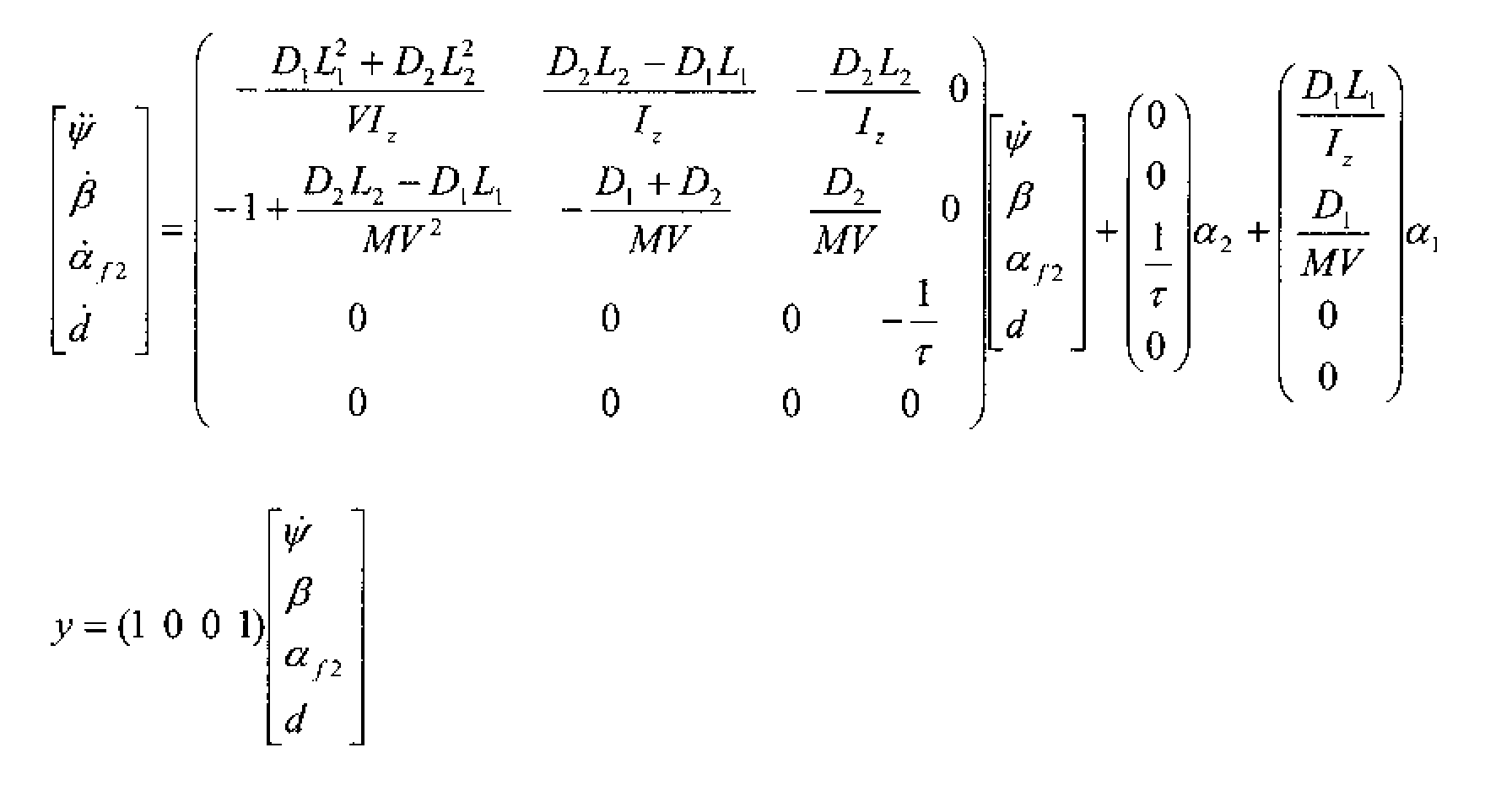
- the state observer 23 may for example be constructed from a non-dangling two-wheeled vehicle model assuming that a step-type disturbance can act directly on the yaw rate of the vehicle on a finite time interval. A dynamics that models the behavior of the actuator can be added.
- the state equation associated with the model extended by the perturbation is as follows: in which there is noted the output considered, M the total mass of the vehicle, I 2 the inertia of the vehicle about a vertical axis passing through its center of gravity, L 1 the distance from the center of gravity to the front axle, L 2 the distance from the center of gravity to the rear axle, L the vehicle wheelbase equal to L1 + L2, D 1 the forward drift rigidity, D 2 the rear drift rigidity, ⁇ 1 the front wheel angle with the longitudinal axis of the vehicle, ⁇ 2 the setpoint angle of the rear wheels, ⁇ f2 the real steering angle of the rear wheels, V the speed of the vehicle, ⁇ ⁇ the yaw rate, ⁇ the angle of drift , i.e., the angle that the vehicle velocity vector makes with the longitudinal axis of said vehicle, and ⁇ the response time of the actuator.
- the state observer 23 makes it possible to estimate the states of the vehicle and all the disturbances that act on the vehicle.
- the state observer can therefore use the following equation: with ⁇ which means that the values are estimated, d the disturbance experienced by the vehicle, and Ko (V) the setting parameter of the state observer which changes according to the speed of the vehicle.
- the four estimated values , ⁇ and, ⁇ and f2 and d and provide an estimate of the state of the vehicle that could be used by other elements of the control unit 11.
- the control unit 11 further comprises a block 24 for calculating the transients.
- the block 24 calculates the control value of the steering angle of the rear wheels 5 and 6 noted transient ⁇ 2 which allows to act on the dynamics of the transient response.
- the calculation can be performed by a pole placement technique.
- Kautsky, J. and NK Nichols "Robust Pole Assignment in Linear State Feedback", Int. J. Control, 41 (1985), pp. 1129-1155.
- the corrector K (Vo) can be calculated, for each chosen speed Vo, by the method of placement of poles described in the aforementioned document.
- the corrector K (V) is then interpolated according to the speed. This gives the control variable:
- Such a setting makes it possible to slow down the dynamic response of the vehicle and suppress oscillations in yaw rate and drift the vehicle.
- this setting allows optimize the passage of a double line change.
- the control unit 11 furthermore comprises a block 25 for calculating the static command denoted ⁇ 2 -static receiving as input the steering angle ⁇ 1 of the front wheels as measured by the sensor 12, the coefficients K 1 , K 2 and K 3 calculated the block 24 and the speed V of the vehicle measured by the sensor 13.
- the ⁇ 2-static control makes it possible to act on the static response of the vehicle and to modify the stabilized value of the yaw rate obtained as a result of a steering wheel of a given amplitude. The result can be expressed by comparison with the static gain that would be obtained on the vehicle whose rear wheels are non-steered.
- Tgs is the setting parameter which can vary, if necessary, depending on the speed V.
- Tgs is equal to 1, the static response of the vehicle is not modified and therefore identical to that of a non-wheeled vehicle guidelines.
- a value of Tgs greater than 1 results in an increase in the static response of the vehicle, while a value less than 1 results in a decrease in the static response of the vehicle.
- Tgs 1.2 for a speed of 90 km / h, this which makes the response of the vehicle more direct and therefore optimize the passage of a double line change.
- the control unit 11 is completed by a subtracter 26, an output 27 and a unit delay 28.
- the subtractor 26 receives on its positive input the control output ⁇ 2-transient of the block 24 and on its negative input the control output ⁇ 2-static block 25.
- the output of the subtractor 26 is connected, on the one hand, to the main output 27 of the control unit 11, and, on the other hand, the unit delay 28, whose output is connected to an input of the status observer 23 to provide the steering angle of the rear wheels at a previous time.
- the present invention proposes a control system of rear wheel steering with closed-loop structure using a controller to change the dynamics of the system and a gain allowing the adjustment of the static gain, all variable according to speed.
- the control strategy allows to adjust the transient part from the vehicle's lateral response to a steering wheel.
- the final adjustment depending on the speed of the vehicle, optimizes the efficiency and ease of passage of a double change of line or still the maneuver at low speed.
- the control strategy allows to adjust the static part of the lateral response of the vehicle to a steering wheel.
- the final setting depending on the speed of the vehicle, allows for example to optimize efficiency and ease of passage of a double line change and / or low speed maneuvering.
- the static and dynamic parts of the vehicle response can be adjusted independently.
- the loop structure closed ensures excellent accuracy and high robustness.
- the setting of the parameters is fast and intuitive, since these parameters are linked to the minimum performance of the vehicle, ie the performance of a non-steering wheeled vehicle. Indeed, setting parameters equal to 1 do not change the behavior of the vehicle, while setting parameters greater than 1 make the more lively and direct behavior and vice versa.
Landscapes
- Engineering & Computer Science (AREA)
- Chemical & Material Sciences (AREA)
- Combustion & Propulsion (AREA)
- Transportation (AREA)
- Mechanical Engineering (AREA)
- Physics & Mathematics (AREA)
- Mathematical Physics (AREA)
- Theoretical Computer Science (AREA)
- Steering Control In Accordance With Driving Conditions (AREA)
- Steering-Linkage Mechanisms And Four-Wheel Steering (AREA)
- Hydraulic Control Valves For Brake Systems (AREA)
- Regulating Braking Force (AREA)
Abstract
Description
- la figure 1 est une vue schématique d'un véhicule équipé d'un système de commande selon un aspect de l'invention ; et
- la figure 2 est un schéma logique du système.


Claims (15)
- Procédé de commande du braquage de roue arrière directrice pour un véhicule à au moins trois roues directrices, dans lequel en fonction de l'angle de braquage de roue avant, de données de déplacement du véhicule comprenant la dérive au centre de gravité du véhicule, et d'une consigne antérieure de braquage de roue arrière, on élabore une consigne actuelle de braquage de roue arrière.
- Procédé selon la revendication 1, dans lequel les données de déplacement du véhicule comprennent la vitesse du véhicule de façon que la consigne actuelle de braquage de roue arrière soit établie en fonction de la vitesse du véhicule.
- Procédé selon la revendication 1 ou 2, dans lequel on élabore une consigne actuelle de braquage de roue arrière avec des paramètres de réglage neutres sur le comportement du véhicule lorsque lesdits paramètres de réglage sont égaux à un.
- Procédé selon l'une quelconque des revendications précédentes, dans lequel les données de déplacement du véhicule comprennent la vitesse de lacet.
- Procédé selon l'une quelconque des revendications précédentes, dans lequel on estime des données d'état du véhicule à partir des données d'entrée.
- Procédé selon la revendication 5, dans lequel les données d'état estimées comprennent la vitesse de lacet ψ, l'angle de dérive β, et l'angle de braquage de roue arrière α2.
- Procédé selon la revendication 6, dans lequel les données d'état estimées comprennent, en outre, une perturbation estimée d and .
- Procédé selon l'une quelconque des revendications précédentes, dans lequel la consigne actuelle de braquage de roue arrière est égale à la différence entre une consigne dynamique et une consigne statique.
- Procédé selon la revendication 8, dans lequel la consigne dynamique est élaborée à partir d'un correcteur appliqué à des données d'état estimées.
- Procédé selon la revendication 8 ou 9, dans lequel la consigne statique est élaborée à partir d'un correcteur appliqué à des données d'état estimées et d'un paramètre de réglage.
- Procédé selon la revendication 11, dans lequel le correcteur est interpolé en fonction de la vitesse.
- Système (10) de commande du braquage de roue arrière directrice (5) pour un véhicule (1) à au moins trois roues directrices, caractérisé par le fait qu'il comprend un moyen d'élaboration d'une consigne actuelle de braquage de roue arrière en fonction de l'angle α1 de braquage de roue avant (3), de données de déplacement du véhicule comprenant la dérive au centre de gravité du véhicule, et d'une consigne antérieure de braquage de roue arrière (5).
- Système selon la revendication 12, caractérisé par le fait qu'il comprend un module (23) d'estimation des données d'état du véhicule à partir des données d'entrée, un module (24) d'élaboration d'une consigne dynamique, un module (25) d'élaboration d'une consigne statique, et un module de combinaison de la consigne dynamique et de la consigne statique.
- Système selon la revendication 13, caractérisé par le fait que ledit module de combinaison est un soustracteur (26).
- Véhicule (1) comprenant un châssis (2) et au moins trois roues directrices (3 à 5) reliées élastiquement au châssis (2), caractérisé par le fait qu'il comprend un système (10) de commande du braquage de roue arrière directrice (5) comprenant un moyen d'élaboration d'une consigne actuelle de braquage de roue arrière en fonction de l'angle α1 de braquage de roue avant (3), de données de déplacement du véhicule comprenant la dérive au centre de gravité du véhicule, et d'une consigne antérieure de braquage de roue arrière (5).
Applications Claiming Priority (2)
| Application Number | Priority Date | Filing Date | Title |
|---|---|---|---|
| FR0314929 | 2003-12-18 | ||
| FR0314929A FR2864001B1 (fr) | 2003-12-18 | 2003-12-18 | Procede et systeme de commande du braquage de roue arriere directrice et vehicule correspondant |
Publications (2)
| Publication Number | Publication Date |
|---|---|
| EP1544080A1 true EP1544080A1 (fr) | 2005-06-22 |
| EP1544080B1 EP1544080B1 (fr) | 2008-08-06 |
Family
ID=34508700
Family Applications (1)
| Application Number | Title | Priority Date | Filing Date |
|---|---|---|---|
| EP04300850A Expired - Lifetime EP1544080B1 (fr) | 2003-12-18 | 2004-12-06 | Procédé et système de commande du braquage de roue arrière directrice et véhicule correspondant |
Country Status (8)
| Country | Link |
|---|---|
| EP (1) | EP1544080B1 (fr) |
| JP (1) | JP4863880B2 (fr) |
| KR (1) | KR101139636B1 (fr) |
| AT (1) | ATE403590T1 (fr) |
| DE (1) | DE602004015554D1 (fr) |
| ES (1) | ES2308129T3 (fr) |
| FR (1) | FR2864001B1 (fr) |
| WO (1) | WO2005061305A1 (fr) |
Cited By (1)
| Publication number | Priority date | Publication date | Assignee | Title |
|---|---|---|---|---|
| FR2991279A1 (fr) * | 2012-06-01 | 2013-12-06 | Renault Sa | Dispositif de controle de trajectoire d'un vehicule. |
Families Citing this family (9)
| Publication number | Priority date | Publication date | Assignee | Title |
|---|---|---|---|---|
| FR2895347B1 (fr) | 2005-12-23 | 2008-02-15 | Renault Sas | Procede et dispositif de commande de l'angle de braquage de roue arriere d'un vehicule automobile |
| FR2896753B1 (fr) | 2006-01-27 | 2008-04-11 | Renault Sas | Procede et dispositif de compensation de variations de couple |
| FR2902067B1 (fr) | 2006-06-09 | 2008-09-26 | Renault Sas | Procede et systeme de commande de roue directrice de vehicule |
| FR2903952B1 (fr) | 2006-07-21 | 2009-06-12 | Renault Sas | Dispositif et procede de surveillance de la commande du braquage de roue arriere directrice. |
| FR2991276B1 (fr) | 2012-06-04 | 2014-05-16 | Renault Sa | Dispositif de controle de trajectoire d'un vehicule |
| FR2992931B1 (fr) | 2012-07-03 | 2014-08-08 | Renault Sa | Dispositif et procede de controle de trajectoire d'un vehicule. |
| FR3026709B1 (fr) | 2014-10-02 | 2018-01-26 | Renault S.A.S | Procede de reglage du comportement d'un vehicule automobile |
| FR3041590B1 (fr) | 2015-09-30 | 2018-08-17 | Renault S.A.S | Systeme de commande de la direction d'un vehicule automobile en cas de collision imminente avec un obstacle |
| US10343685B2 (en) * | 2016-09-28 | 2019-07-09 | Baidu Usa Llc | Physical model and machine learning combined method to simulate autonomous vehicle movement |
Citations (6)
| Publication number | Priority date | Publication date | Assignee | Title |
|---|---|---|---|---|
| US4706979A (en) * | 1985-07-12 | 1987-11-17 | Nissan Motor Co., Ltd. | Steering control system for wheeled vehicle |
| DE3816254A1 (de) * | 1988-05-11 | 1989-11-23 | Siemens Ag | Steuereinheit zur lenkung der hinterraeder eines strassenfahrzeuges |
| EP0588135A1 (fr) * | 1992-09-01 | 1994-03-23 | Matsushita Electric Industrial Co., Ltd. | Dispositif de commande de l'angle de direction des roues arrières d'un véhicule à quatre roues directrices |
| EP0663333A1 (fr) * | 1994-01-14 | 1995-07-19 | Matsushita Electric Industrial Co., Ltd. | Dispositif de commande d'angle de direction |
| EP0721877A1 (fr) * | 1995-01-12 | 1996-07-17 | Toyota Jidosha Kabushiki Kaisha | Appareil de commande du comportement d'un véhicule capable de changer la limite supérieure de sa sortie en fonction de la disponibilité d'un autre appareil de commande du comportement d'un véhicule |
| US5745862A (en) * | 1994-08-08 | 1998-04-28 | Toyota Jidosha Kabushiki Kaisha | Movement state control apparatus for wheeled vehicle |
Family Cites Families (3)
| Publication number | Priority date | Publication date | Assignee | Title |
|---|---|---|---|---|
| JPH0939821A (ja) * | 1995-08-02 | 1997-02-10 | Mitsubishi Motors Corp | 車両の後輪操舵制御装置 |
| JPH09249145A (ja) * | 1996-03-15 | 1997-09-22 | Toyota Motor Corp | 車両の運動制御装置 |
| DE10039782A1 (de) * | 2000-08-16 | 2002-02-28 | Daimler Chrysler Ag | Verfahren zur Regelung der Gier-und Querdynamik bei einem Straßenfahrzeug |
-
2003
- 2003-12-18 FR FR0314929A patent/FR2864001B1/fr not_active Expired - Fee Related
-
2004
- 2004-12-06 EP EP04300850A patent/EP1544080B1/fr not_active Expired - Lifetime
- 2004-12-06 AT AT04300850T patent/ATE403590T1/de not_active IP Right Cessation
- 2004-12-06 ES ES04300850T patent/ES2308129T3/es not_active Expired - Lifetime
- 2004-12-06 DE DE602004015554T patent/DE602004015554D1/de not_active Expired - Lifetime
- 2004-12-16 JP JP2006544521A patent/JP4863880B2/ja not_active Expired - Fee Related
- 2004-12-16 WO PCT/FR2004/050705 patent/WO2005061305A1/fr not_active Ceased
- 2004-12-16 KR KR1020067014289A patent/KR101139636B1/ko not_active Expired - Fee Related
Patent Citations (6)
| Publication number | Priority date | Publication date | Assignee | Title |
|---|---|---|---|---|
| US4706979A (en) * | 1985-07-12 | 1987-11-17 | Nissan Motor Co., Ltd. | Steering control system for wheeled vehicle |
| DE3816254A1 (de) * | 1988-05-11 | 1989-11-23 | Siemens Ag | Steuereinheit zur lenkung der hinterraeder eines strassenfahrzeuges |
| EP0588135A1 (fr) * | 1992-09-01 | 1994-03-23 | Matsushita Electric Industrial Co., Ltd. | Dispositif de commande de l'angle de direction des roues arrières d'un véhicule à quatre roues directrices |
| EP0663333A1 (fr) * | 1994-01-14 | 1995-07-19 | Matsushita Electric Industrial Co., Ltd. | Dispositif de commande d'angle de direction |
| US5745862A (en) * | 1994-08-08 | 1998-04-28 | Toyota Jidosha Kabushiki Kaisha | Movement state control apparatus for wheeled vehicle |
| EP0721877A1 (fr) * | 1995-01-12 | 1996-07-17 | Toyota Jidosha Kabushiki Kaisha | Appareil de commande du comportement d'un véhicule capable de changer la limite supérieure de sa sortie en fonction de la disponibilité d'un autre appareil de commande du comportement d'un véhicule |
Cited By (4)
| Publication number | Priority date | Publication date | Assignee | Title |
|---|---|---|---|---|
| FR2991279A1 (fr) * | 2012-06-01 | 2013-12-06 | Renault Sa | Dispositif de controle de trajectoire d'un vehicule. |
| WO2013178899A3 (fr) * | 2012-06-01 | 2014-03-20 | Renault S.A.S. | Dispositif de controle de trajectoire d'un vehicule |
| CN104428187A (zh) * | 2012-06-01 | 2015-03-18 | 雷诺股份公司 | 用于控制车辆路线的装置 |
| CN104428187B (zh) * | 2012-06-01 | 2018-04-17 | 雷诺股份公司 | 用于控制车辆路线的装置 |
Also Published As
| Publication number | Publication date |
|---|---|
| ATE403590T1 (de) | 2008-08-15 |
| KR20060132865A (ko) | 2006-12-22 |
| WO2005061305A1 (fr) | 2005-07-07 |
| KR101139636B1 (ko) | 2012-05-15 |
| DE602004015554D1 (de) | 2008-09-18 |
| JP2007514600A (ja) | 2007-06-07 |
| FR2864001A1 (fr) | 2005-06-24 |
| ES2308129T3 (es) | 2008-12-01 |
| FR2864001B1 (fr) | 2007-11-23 |
| JP4863880B2 (ja) | 2012-01-25 |
| EP1544080B1 (fr) | 2008-08-06 |
Similar Documents
| Publication | Publication Date | Title |
|---|---|---|
| EP3938260B1 (fr) | Procédé d'élaboration d'une consigne de pilotage mixte d'un système de braquage de roues et d'un système de freinage différentiel d'un véhicule automobile | |
| EP2043901B1 (fr) | Dispositif et procédé de surveillance de la commande du braquage de roue arrière directrice | |
| EP1544080B1 (fr) | Procédé et système de commande du braquage de roue arrière directrice et véhicule correspondant | |
| EP1716039B1 (fr) | Procede et systeme de commande du braquage de roue arriere directrice et vehicule ainsi equipe | |
| EP1901933B1 (fr) | Procédé et système anti-roulis d'un véhicule et véhicule correspondant | |
| EP1706307B1 (fr) | Procede et systeme de commande du braquage de roue arriere directrice et vehicule correspondant | |
| EP2027004B1 (fr) | Procede et systeme de commande de roue directrice de vehicule | |
| EP2032415B1 (fr) | Procede et systeme de commande du braquage de roue arriere directrice et vehicule correspondant | |
| EP1901932B1 (fr) | Procede et systeme anti-roulis d'un vehicule et vehicule correspondant | |
| WO2020260114A1 (fr) | Procédé de régulation de la position latérale d'un véhicule | |
| FR3092914A1 (fr) | Procédé de détermination de la trajectoire d'un véhicule comprenant quatre roues directrices | |
| FR2856648A1 (fr) | Procede et systeme de commande d'assistance de direction electrique de vehicule automobile | |
| WO2007071853A1 (fr) | Dispositif anti-roulis pour vehicules | |
| WO2024104837A1 (fr) | Procédé de pilotage d'un véhicule automobile au centre de sa voie de circulation | |
| WO2007003800A2 (fr) | Procede de commande d'au moins un actionneur de barres anti-roulis a bord d'un vehicule | |
| WO2008107613A1 (fr) | Systeme et procede de commande en boucle ouverte d'un systeme antiroulis actif par typage de la vitesse en lacet d'un vehicule base sur un modele non lineaire deux roues | |
| EP1963116A1 (fr) | Dispositif anti-roulis pour vehicules | |
| FR2895349A1 (fr) | Procede et systeme de pilotage d'un dispositif de carrossage actif avant ou arriere pour vehicule automobile. | |
| FR2888194A1 (fr) | Procede et systeme de commande de carrossage actif et vehicule ainsi equipe |
Legal Events
| Date | Code | Title | Description |
|---|---|---|---|
| PUAI | Public reference made under article 153(3) epc to a published international application that has entered the european phase |
Free format text: ORIGINAL CODE: 0009012 |
|
| AK | Designated contracting states |
Kind code of ref document: A1 Designated state(s): AT BE BG CH CY CZ DE DK EE ES FI FR GB GR HU IE IS IT LI LT LU MC NL PL PT RO SE SI SK TR |
|
| AX | Request for extension of the european patent |
Extension state: AL BA HR LV MK YU |
|
| 17P | Request for examination filed |
Effective date: 20050726 |
|
| AKX | Designation fees paid |
Designated state(s): AT BE BG CH CY CZ DE DK EE ES FI FR GB GR HU IE IS IT LI LT LU MC NL PL PT RO SE SI SK TR |
|
| 17Q | First examination report despatched |
Effective date: 20060210 |
|
| 17Q | First examination report despatched |
Effective date: 20060210 |
|
| GRAP | Despatch of communication of intention to grant a patent |
Free format text: ORIGINAL CODE: EPIDOSNIGR1 |
|
| GRAS | Grant fee paid |
Free format text: ORIGINAL CODE: EPIDOSNIGR3 |
|
| GRAA | (expected) grant |
Free format text: ORIGINAL CODE: 0009210 |
|
| AK | Designated contracting states |
Kind code of ref document: B1 Designated state(s): AT BE BG CH CY CZ DE DK EE ES FI FR GB GR HU IE IS IT LI LT LU MC NL PL PT RO SE SI SK TR |
|
| REG | Reference to a national code |
Ref country code: GB Ref legal event code: FG4D Free format text: NOT ENGLISH |
|
| REG | Reference to a national code |
Ref country code: CH Ref legal event code: EP |
|
| REG | Reference to a national code |
Ref country code: IE Ref legal event code: FG4D Free format text: LANGUAGE OF EP DOCUMENT: FRENCH |
|
| REF | Corresponds to: |
Ref document number: 602004015554 Country of ref document: DE Date of ref document: 20080918 Kind code of ref document: P |
|
| REG | Reference to a national code |
Ref country code: SE Ref legal event code: TRGR |
|
| REG | Reference to a national code |
Ref country code: ES Ref legal event code: FG2A Ref document number: 2308129 Country of ref document: ES Kind code of ref document: T3 |
|
| PG25 | Lapsed in a contracting state [announced via postgrant information from national office to epo] |
Ref country code: NL Free format text: LAPSE BECAUSE OF FAILURE TO SUBMIT A TRANSLATION OF THE DESCRIPTION OR TO PAY THE FEE WITHIN THE PRESCRIBED TIME-LIMIT Effective date: 20080806 Ref country code: IS Free format text: LAPSE BECAUSE OF FAILURE TO SUBMIT A TRANSLATION OF THE DESCRIPTION OR TO PAY THE FEE WITHIN THE PRESCRIBED TIME-LIMIT Effective date: 20081206 Ref country code: LT Free format text: LAPSE BECAUSE OF FAILURE TO SUBMIT A TRANSLATION OF THE DESCRIPTION OR TO PAY THE FEE WITHIN THE PRESCRIBED TIME-LIMIT Effective date: 20080806 |
|
| PG25 | Lapsed in a contracting state [announced via postgrant information from national office to epo] |
Ref country code: FI Free format text: LAPSE BECAUSE OF FAILURE TO SUBMIT A TRANSLATION OF THE DESCRIPTION OR TO PAY THE FEE WITHIN THE PRESCRIBED TIME-LIMIT Effective date: 20080806 Ref country code: SI Free format text: LAPSE BECAUSE OF FAILURE TO SUBMIT A TRANSLATION OF THE DESCRIPTION OR TO PAY THE FEE WITHIN THE PRESCRIBED TIME-LIMIT Effective date: 20080806 Ref country code: AT Free format text: LAPSE BECAUSE OF FAILURE TO SUBMIT A TRANSLATION OF THE DESCRIPTION OR TO PAY THE FEE WITHIN THE PRESCRIBED TIME-LIMIT Effective date: 20080806 |
|
| REG | Reference to a national code |
Ref country code: IE Ref legal event code: FD4D |
|
| PG25 | Lapsed in a contracting state [announced via postgrant information from national office to epo] |
Ref country code: BG Free format text: LAPSE BECAUSE OF FAILURE TO SUBMIT A TRANSLATION OF THE DESCRIPTION OR TO PAY THE FEE WITHIN THE PRESCRIBED TIME-LIMIT Effective date: 20081106 Ref country code: IE Free format text: LAPSE BECAUSE OF FAILURE TO SUBMIT A TRANSLATION OF THE DESCRIPTION OR TO PAY THE FEE WITHIN THE PRESCRIBED TIME-LIMIT Effective date: 20080806 Ref country code: DK Free format text: LAPSE BECAUSE OF FAILURE TO SUBMIT A TRANSLATION OF THE DESCRIPTION OR TO PAY THE FEE WITHIN THE PRESCRIBED TIME-LIMIT Effective date: 20080806 |
|
| PG25 | Lapsed in a contracting state [announced via postgrant information from national office to epo] |
Ref country code: RO Free format text: LAPSE BECAUSE OF FAILURE TO SUBMIT A TRANSLATION OF THE DESCRIPTION OR TO PAY THE FEE WITHIN THE PRESCRIBED TIME-LIMIT Effective date: 20080806 Ref country code: PT Free format text: LAPSE BECAUSE OF FAILURE TO SUBMIT A TRANSLATION OF THE DESCRIPTION OR TO PAY THE FEE WITHIN THE PRESCRIBED TIME-LIMIT Effective date: 20090106 Ref country code: CZ Free format text: LAPSE BECAUSE OF FAILURE TO SUBMIT A TRANSLATION OF THE DESCRIPTION OR TO PAY THE FEE WITHIN THE PRESCRIBED TIME-LIMIT Effective date: 20080806 Ref country code: SK Free format text: LAPSE BECAUSE OF FAILURE TO SUBMIT A TRANSLATION OF THE DESCRIPTION OR TO PAY THE FEE WITHIN THE PRESCRIBED TIME-LIMIT Effective date: 20080806 |
|
| PLBE | No opposition filed within time limit |
Free format text: ORIGINAL CODE: 0009261 |
|
| STAA | Information on the status of an ep patent application or granted ep patent |
Free format text: STATUS: NO OPPOSITION FILED WITHIN TIME LIMIT |
|
| 26N | No opposition filed |
Effective date: 20090507 |
|
| PG25 | Lapsed in a contracting state [announced via postgrant information from national office to epo] |
Ref country code: MC Free format text: LAPSE BECAUSE OF NON-PAYMENT OF DUE FEES Effective date: 20081231 Ref country code: EE Free format text: LAPSE BECAUSE OF FAILURE TO SUBMIT A TRANSLATION OF THE DESCRIPTION OR TO PAY THE FEE WITHIN THE PRESCRIBED TIME-LIMIT Effective date: 20080806 |
|
| REG | Reference to a national code |
Ref country code: CH Ref legal event code: PL |
|
| PG25 | Lapsed in a contracting state [announced via postgrant information from national office to epo] |
Ref country code: LI Free format text: LAPSE BECAUSE OF NON-PAYMENT OF DUE FEES Effective date: 20081231 Ref country code: CH Free format text: LAPSE BECAUSE OF NON-PAYMENT OF DUE FEES Effective date: 20081231 |
|
| PG25 | Lapsed in a contracting state [announced via postgrant information from national office to epo] |
Ref country code: PL Free format text: LAPSE BECAUSE OF FAILURE TO SUBMIT A TRANSLATION OF THE DESCRIPTION OR TO PAY THE FEE WITHIN THE PRESCRIBED TIME-LIMIT Effective date: 20080806 |
|
| PG25 | Lapsed in a contracting state [announced via postgrant information from national office to epo] |
Ref country code: LU Free format text: LAPSE BECAUSE OF NON-PAYMENT OF DUE FEES Effective date: 20081206 Ref country code: CY Free format text: LAPSE BECAUSE OF FAILURE TO SUBMIT A TRANSLATION OF THE DESCRIPTION OR TO PAY THE FEE WITHIN THE PRESCRIBED TIME-LIMIT Effective date: 20080806 Ref country code: HU Free format text: LAPSE BECAUSE OF FAILURE TO SUBMIT A TRANSLATION OF THE DESCRIPTION OR TO PAY THE FEE WITHIN THE PRESCRIBED TIME-LIMIT Effective date: 20090207 |
|
| PG25 | Lapsed in a contracting state [announced via postgrant information from national office to epo] |
Ref country code: TR Free format text: LAPSE BECAUSE OF FAILURE TO SUBMIT A TRANSLATION OF THE DESCRIPTION OR TO PAY THE FEE WITHIN THE PRESCRIBED TIME-LIMIT Effective date: 20080806 |
|
| PG25 | Lapsed in a contracting state [announced via postgrant information from national office to epo] |
Ref country code: GR Free format text: LAPSE BECAUSE OF FAILURE TO SUBMIT A TRANSLATION OF THE DESCRIPTION OR TO PAY THE FEE WITHIN THE PRESCRIBED TIME-LIMIT Effective date: 20081107 |
|
| PGFP | Annual fee paid to national office [announced via postgrant information from national office to epo] |
Ref country code: SE Payment date: 20101214 Year of fee payment: 7 |
|
| PGFP | Annual fee paid to national office [announced via postgrant information from national office to epo] |
Ref country code: BE Payment date: 20111229 Year of fee payment: 8 |
|
| REG | Reference to a national code |
Ref country code: SE Ref legal event code: EUG |
|
| PG25 | Lapsed in a contracting state [announced via postgrant information from national office to epo] |
Ref country code: SE Free format text: LAPSE BECAUSE OF NON-PAYMENT OF DUE FEES Effective date: 20111207 |
|
| BERE | Be: lapsed |
Owner name: RENAULT S.A.S. Effective date: 20121231 |
|
| PG25 | Lapsed in a contracting state [announced via postgrant information from national office to epo] |
Ref country code: BE Free format text: LAPSE BECAUSE OF NON-PAYMENT OF DUE FEES Effective date: 20121231 |
|
| REG | Reference to a national code |
Ref country code: FR Ref legal event code: PLFP Year of fee payment: 12 |
|
| REG | Reference to a national code |
Ref country code: FR Ref legal event code: PLFP Year of fee payment: 13 |
|
| REG | Reference to a national code |
Ref country code: FR Ref legal event code: PLFP Year of fee payment: 14 |
|
| PGFP | Annual fee paid to national office [announced via postgrant information from national office to epo] |
Ref country code: GB Payment date: 20211221 Year of fee payment: 18 |
|
| PGFP | Annual fee paid to national office [announced via postgrant information from national office to epo] |
Ref country code: IT Payment date: 20211224 Year of fee payment: 18 Ref country code: ES Payment date: 20220218 Year of fee payment: 18 |
|
| PGFP | Annual fee paid to national office [announced via postgrant information from national office to epo] |
Ref country code: FR Payment date: 20221222 Year of fee payment: 19 Ref country code: DE Payment date: 20221213 Year of fee payment: 19 |
|
| P01 | Opt-out of the competence of the unified patent court (upc) registered |
Effective date: 20230608 |
|
| GBPC | Gb: european patent ceased through non-payment of renewal fee |
Effective date: 20221206 |
|
| PG25 | Lapsed in a contracting state [announced via postgrant information from national office to epo] |
Ref country code: GB Free format text: LAPSE BECAUSE OF NON-PAYMENT OF DUE FEES Effective date: 20221206 |
|
| REG | Reference to a national code |
Ref country code: ES Ref legal event code: FD2A Effective date: 20240126 |
|
| PG25 | Lapsed in a contracting state [announced via postgrant information from national office to epo] |
Ref country code: IT Free format text: LAPSE BECAUSE OF NON-PAYMENT OF DUE FEES Effective date: 20221206 |
|
| PG25 | Lapsed in a contracting state [announced via postgrant information from national office to epo] |
Ref country code: ES Free format text: LAPSE BECAUSE OF NON-PAYMENT OF DUE FEES Effective date: 20221207 |
|
| PG25 | Lapsed in a contracting state [announced via postgrant information from national office to epo] |
Ref country code: ES Free format text: LAPSE BECAUSE OF NON-PAYMENT OF DUE FEES Effective date: 20221207 |
|
| REG | Reference to a national code |
Ref country code: DE Ref legal event code: R119 Ref document number: 602004015554 Country of ref document: DE |
|
| PG25 | Lapsed in a contracting state [announced via postgrant information from national office to epo] |
Ref country code: DE Free format text: LAPSE BECAUSE OF NON-PAYMENT OF DUE FEES Effective date: 20240702 |
|
| PG25 | Lapsed in a contracting state [announced via postgrant information from national office to epo] |
Ref country code: FR Free format text: LAPSE BECAUSE OF NON-PAYMENT OF DUE FEES Effective date: 20231231 |
|
| PG25 | Lapsed in a contracting state [announced via postgrant information from national office to epo] |
Ref country code: FR Free format text: LAPSE BECAUSE OF NON-PAYMENT OF DUE FEES Effective date: 20231231 Ref country code: DE Free format text: LAPSE BECAUSE OF NON-PAYMENT OF DUE FEES Effective date: 20240702 |