EP1544009A2 - Valve arrangement, particularly for adjusting the flow of heating or cooling liqiud in a motor vehicle - Google Patents
Valve arrangement, particularly for adjusting the flow of heating or cooling liqiud in a motor vehicle Download PDFInfo
- Publication number
- EP1544009A2 EP1544009A2 EP04030040A EP04030040A EP1544009A2 EP 1544009 A2 EP1544009 A2 EP 1544009A2 EP 04030040 A EP04030040 A EP 04030040A EP 04030040 A EP04030040 A EP 04030040A EP 1544009 A2 EP1544009 A2 EP 1544009A2
- Authority
- EP
- European Patent Office
- Prior art keywords
- valve
- valve member
- flow
- line
- temperature
- Prior art date
- Legal status (The legal status is an assumption and is not a legal conclusion. Google has not performed a legal analysis and makes no representation as to the accuracy of the status listed.)
- Granted
Links
- 238000010438 heat treatment Methods 0.000 title claims abstract description 98
- 238000001816 cooling Methods 0.000 title description 3
- 239000002826 coolant Substances 0.000 claims abstract description 5
- 239000012530 fluid Substances 0.000 claims description 92
- 230000001419 dependent effect Effects 0.000 claims description 31
- 230000009471 action Effects 0.000 claims description 8
- 238000004891 communication Methods 0.000 claims description 6
- 230000008602 contraction Effects 0.000 claims description 6
- 238000006073 displacement reaction Methods 0.000 claims description 3
- 238000000605 extraction Methods 0.000 claims description 2
- 230000004044 response Effects 0.000 claims description 2
- 238000002485 combustion reaction Methods 0.000 description 19
- 239000007788 liquid Substances 0.000 description 15
- 230000033001 locomotion Effects 0.000 description 9
- 230000000694 effects Effects 0.000 description 5
- 230000006870 function Effects 0.000 description 5
- 230000006399 behavior Effects 0.000 description 4
- 125000006850 spacer group Chemical group 0.000 description 4
- 230000008859 change Effects 0.000 description 3
- 230000017525 heat dissipation Effects 0.000 description 3
- 210000000056 organ Anatomy 0.000 description 3
- 239000012781 shape memory material Substances 0.000 description 3
- 238000012546 transfer Methods 0.000 description 3
- 230000007704 transition Effects 0.000 description 3
- 238000013461 design Methods 0.000 description 2
- 238000013021 overheating Methods 0.000 description 2
- 230000001737 promoting effect Effects 0.000 description 2
- 238000005086 pumping Methods 0.000 description 2
- 230000002269 spontaneous effect Effects 0.000 description 2
- 238000011144 upstream manufacturing Methods 0.000 description 2
- XLYOFNOQVPJJNP-UHFFFAOYSA-N water Substances O XLYOFNOQVPJJNP-UHFFFAOYSA-N 0.000 description 2
- 238000010521 absorption reaction Methods 0.000 description 1
- 230000005540 biological transmission Effects 0.000 description 1
- 230000000903 blocking effect Effects 0.000 description 1
- 239000012809 cooling fluid Substances 0.000 description 1
- 230000003292 diminished effect Effects 0.000 description 1
- 238000010348 incorporation Methods 0.000 description 1
- 238000012423 maintenance Methods 0.000 description 1
- 238000004519 manufacturing process Methods 0.000 description 1
- 239000000463 material Substances 0.000 description 1
- 230000002093 peripheral effect Effects 0.000 description 1
- 230000036413 temperature sense Effects 0.000 description 1
Images


Classifications
-
- F—MECHANICAL ENGINEERING; LIGHTING; HEATING; WEAPONS; BLASTING
- F02—COMBUSTION ENGINES; HOT-GAS OR COMBUSTION-PRODUCT ENGINE PLANTS
- F02N—STARTING OF COMBUSTION ENGINES; STARTING AIDS FOR SUCH ENGINES, NOT OTHERWISE PROVIDED FOR
- F02N19/00—Starting aids for combustion engines, not otherwise provided for
- F02N19/02—Aiding engine start by thermal means, e.g. using lighted wicks
- F02N19/04—Aiding engine start by thermal means, e.g. using lighted wicks by heating of fluids used in engines
- F02N19/10—Aiding engine start by thermal means, e.g. using lighted wicks by heating of fluids used in engines by heating of engine coolants
-
- B—PERFORMING OPERATIONS; TRANSPORTING
- B60—VEHICLES IN GENERAL
- B60H—ARRANGEMENTS OF HEATING, COOLING, VENTILATING OR OTHER AIR-TREATING DEVICES SPECIALLY ADAPTED FOR PASSENGER OR GOODS SPACES OF VEHICLES
- B60H1/00—Heating, cooling or ventilating [HVAC] devices
- B60H1/00485—Valves for air-conditioning devices, e.g. thermostatic valves
-
- G—PHYSICS
- G05—CONTROLLING; REGULATING
- G05D—SYSTEMS FOR CONTROLLING OR REGULATING NON-ELECTRIC VARIABLES
- G05D23/00—Control of temperature
- G05D23/01—Control of temperature without auxiliary power
- G05D23/13—Control of temperature without auxiliary power by varying the mixing ratio of two fluids having different temperatures
- G05D23/1306—Control of temperature without auxiliary power by varying the mixing ratio of two fluids having different temperatures for liquids
- G05D23/132—Control of temperature without auxiliary power by varying the mixing ratio of two fluids having different temperatures for liquids with temperature sensing element
- G05D23/1333—Control of temperature without auxiliary power by varying the mixing ratio of two fluids having different temperatures for liquids with temperature sensing element measuring the temperature of incoming fluid
-
- F—MECHANICAL ENGINEERING; LIGHTING; HEATING; WEAPONS; BLASTING
- F01—MACHINES OR ENGINES IN GENERAL; ENGINE PLANTS IN GENERAL; STEAM ENGINES
- F01P—COOLING OF MACHINES OR ENGINES IN GENERAL; COOLING OF INTERNAL-COMBUSTION ENGINES
- F01P5/00—Pumping cooling-air or liquid coolants
- F01P5/10—Pumping liquid coolant; Arrangements of coolant pumps
- F01P2005/105—Using two or more pumps
-
- F—MECHANICAL ENGINEERING; LIGHTING; HEATING; WEAPONS; BLASTING
- F01—MACHINES OR ENGINES IN GENERAL; ENGINE PLANTS IN GENERAL; STEAM ENGINES
- F01P—COOLING OF MACHINES OR ENGINES IN GENERAL; COOLING OF INTERNAL-COMBUSTION ENGINES
- F01P7/00—Controlling of coolant flow
- F01P7/14—Controlling of coolant flow the coolant being liquid
- F01P2007/143—Controlling of coolant flow the coolant being liquid using restrictions
-
- F—MECHANICAL ENGINEERING; LIGHTING; HEATING; WEAPONS; BLASTING
- F01—MACHINES OR ENGINES IN GENERAL; ENGINE PLANTS IN GENERAL; STEAM ENGINES
- F01P—COOLING OF MACHINES OR ENGINES IN GENERAL; COOLING OF INTERNAL-COMBUSTION ENGINES
- F01P2037/00—Controlling
- F01P2037/02—Controlling starting
-
- F—MECHANICAL ENGINEERING; LIGHTING; HEATING; WEAPONS; BLASTING
- F01—MACHINES OR ENGINES IN GENERAL; ENGINE PLANTS IN GENERAL; STEAM ENGINES
- F01P—COOLING OF MACHINES OR ENGINES IN GENERAL; COOLING OF INTERNAL-COMBUSTION ENGINES
- F01P2060/00—Cooling circuits using auxiliaries
- F01P2060/18—Heater
Abstract
Description
Die vorliegende Erfindung betrifft eine Ventilanordnung, insbesondere zur Einstellung der Heizmittel-/Kühlmittelströmung in einem Kraftfahrzeug, welche Ventilanordnung ein Ventilorgan umfasst, das in Abhängigkeit von einer zwischen einer ersten Leitung und einer zweiten Leitung vorherrschenden Druckdifferenz zwischen einer ersten Verbindungsstellung und einer zweiten Verbindungsstellung verstellbar ist.The present invention relates to a valve arrangement, in particular for Setting the Heizmittel- / coolant flow in a motor vehicle, which Valve arrangement comprises a valve member, which in response to a prevailing between a first line and a second line Pressure difference between a first connection position and a second Connection position is adjustable.
Eine derartige Ventilanordnung bzw. ein Heizsystem, in welches eine derartige
Ventilanordnung integriert ist, ist aus der DE 44 46 152 A1 bekannt.
Bei diesem bekannten Heizsystem sind zwei Wärmequellen vorgesehen.
Dies ist zum einen eine Brennkraftmaschine, die im Verbrennungsbetrieb
Wärme erzeugt und diese auf ein flüssiges Medium, im Allgemeinen
Wasser, überträgt. Weiterhin ist als zweite Wärmequelle ein Heizgerät vorhanden,
das im Allgemeinen auch brennstoffbetrieben ist. Auch durch dieses
Heizgerät kann Wärme auf das flüssige Medium übertragen werden. Die in
dem flüssigem Medium transportierte Wärme kann dann in einem Wärmetauscher
auf die in den Fahrzeuginnenraum einzuleitende Luft übertragen
werden. Jedem der Wärme erzeugenden Systembereiche, also der
Brennkraftmaschine und dem Zusatzheizgerät, ist jeweils eine Förderpumpe
zugeordnet, um in verschiedenen Betriebsphasen dafür zu sorgen, dass das
in einem Leitungssystem zirkulierende flüssige Medium in Strömung versetzt
bzw. gehalten wird.Such a valve arrangement or a heating system, in which such
Valve assembly is integrated, is known from
Bei derartigen Heizsystemen sind verschiedene Betriebsmodi möglich bzw. gewünscht. So wird beispielsweise bei Inbetriebnahme eines Fahrzeugs zunächst nur die zweite Wärmequelle, also das Zusatzheizgerät, betrieben, um im Vorwärmmodus das Fahrzeug vorzuwärmen. Dies bedeutet, dass der Wärmetauscher zunächst nur mit flüssigem Medium gespeist wird, das in der zusätzlichen Heizeinrichtung erwärmt worden ist. Da in dieser Betriebsphase der Druck in einer von dem zusätzlichen Heizgerät weg führenden Leitung höher ist, als der Druck in einer von der Brennkraftmaschine weg führenden Leitung, ist ein druckabhängig verstellbares Ventilorgan so gestellt, dass es die vorangehend angesprochene Zirkulation vom Zusatzheizgerät zum Wärmetauscher ermöglicht, eine Zirkulation durch die Brennkraftmaschine aber im Wesentlichen unterbindet und hier nur einen Minimalstrom zulässt. Diesem druckabhängig verstellbaren Ventilorgan ist ferner ein Formgedächtniselement zugeordnet, das temperaturabhängig auf das Ventilorgan einwirken kann. Solange das von der Brennkraftmaschine zu der Ventilanordnung strömende und im Rahmen des Minimalstroms diese auch überströmende flüssige Medium eine vergleichsweise niedrige Temperatur hat, belässt das Formgedächtniselement das Ventilorgan in seiner druckdifferenzenmäßig vorgegebenen Stellung, in welcher das Durchströmen der Brennkraftmaschine im Wesentlichen unterbunden ist. Steigt jedoch die Temperatur des von der Brennkraftmaschine zur Ventilanordnung strömenden flüssigen Mediums über die Schalttemperatur des Formgedächtniselements an, so beaufschlagt dieses das Ventilorgan entgegen der auf dieses einwirkenden Kraft, um auch die Durchströmung der Brennkraftmaschine über den Minimalstrom hinausgehend zuzulassen. In dieser Phase, in welcher die Brennkraftmaschine selbst noch nicht notwendigerweise in Betrieb gesetzt ist, durchströmt also das von der zusätzlichen Heizeinrichtung erwärmte flüssige Medium nicht nur den Wärmetauscher, sondern auch die Brennkraftmaschine und trägt somit zur Vorwärmung derselben bei. Fällt beim Durchströmen der Brennkraftmaschine die Temperatur des flüssigen Mediums wieder unter die Schalttemperatur des Formgedächtniselements ab, so hebt diese seine Beaufschlagungswirkung auf, und das Ventilorgan kehrt druckbedingt wieder in diejenige Stellung zurück, in welcher es die Durchströmung der Brennkraftmaschine mit dem flüssigen Medium im Wesentlichen unterbindet. Auf diese Art und Weise kann sichergestellt werden, dass ausreichend Wärme zur Übertragung auf die in den Fahrzeuginnenraum einzuleitende Luft bereitgestellt wird. Wird die Brennkraftmaschine dann in Betrieb gesetzt, wird im Allgemeinen auch die dieser zugeordnete Flüssigkeitsförderpumpe aktiviert, mit der Folge, dass der Druck des die Brennkraftmaschine durchströmenden flüssigen Mediums ansteigt und somit druckbedingt das Ventilorgan die Durchströmung der Brennkraftmaschine zulassen wird, selbst wenn die Temperatur des zu diesem Zeitpunkt durch die Brennkraftmaschine hindurchgeströmten flüssigen Mediums unter der Schalltemperatur des Formgedächtniselements ist.In such heating systems different operating modes are possible or desired. Thus, for example, when commissioning a vehicle first only the second heat source, so the auxiliary heater, operated to preheat the vehicle in preheat mode. This means that the Heat exchanger is initially fed only with liquid medium, in the additional heating device has been heated. Because in this operating phase the pressure in a pipe leading away from the additional heater is higher than the pressure in a leading away from the engine Line, a pressure-dependent adjustable valve member is placed so that it the above-mentioned circulation from the auxiliary heater to Heat exchanger allows circulation through the internal combustion engine but essentially prevents and allows only a minimum current here. This pressure-dependent adjustable valve member is also a Assigned shape memory element, the temperature-dependent on the Can act on the valve body. As long as that of the internal combustion engine to the Valve arrangement flowing and in the context of the minimum current this too overflowing liquid medium a comparatively low temperature has the shape memory element leaves the valve member in his pressure difference predetermined position in which the flow the internal combustion engine is substantially prevented. Rises, however the temperature of the flowing from the internal combustion engine to the valve assembly liquid medium on the switching temperature of the shape memory element on, so this acts on the valve member against the on this acting force to the flow of the internal combustion engine to allow beyond the minimum current. In this phase, in which the internal combustion engine itself is not necessarily in Operation is set, thus flows through that of the additional heater heated liquid medium not only the heat exchanger, but also the internal combustion engine and thus contributes to the preheating of the same. falls when flowing through the internal combustion engine, the temperature of the liquid Medium again below the switching temperature of the shape memory element from, so this lifts its Beaufschlagungswirkung, and the valve member returns due to pressure back to that position in which it is the Flow through the internal combustion engine with the liquid medium in Substantially inhibits. In this way can be ensured be that sufficient heat for transfer to the in the vehicle interior provided air is provided. Will the internal combustion engine then put into operation, this is generally also the associated liquid feed pump is activated, with the result that the pressure of the internal combustion engine flowing through the liquid medium increases and thus by pressure, the valve member, the flow through the Internal combustion engine will allow, even if the temperature of the too this time passed through the internal combustion engine liquid medium below the sound temperature of the shape memory element is.
Es ist die Aufgabe der vorliegenden Erfindung, eine Ventilanordnung, insbesondere zur Einstellung der Heizmittel-/Kühlmittelströmung in einem Kraftfahrzeug vorzusehen, mit welcher verbessert auf die Betriebsverhältnisse, insbesondere Temperaturverhältnisse, reagiert werden kann.It is the object of the present invention to provide a valve arrangement, in particular for adjusting the Heizmittel- / coolant flow in a motor vehicle to provide, with which improved on the operating conditions, especially temperature conditions, can be reacted.
Erfindungsgemäß wird diese Aufgabe gelöst durch eine Ventilanordnung, insbesondere zur Einstellung der Heizmittel-/Kühlmittelströmung in einem Kraftfahrzeug, umfassend ein erstes Ventilorgan, das in Abhängigkeit von einer zwischen einer ersten Leitung und einer zweiten Leitung vorherrschenden Druckdifferenz zwischen einer ersten Verbindungsstellung und einer zweiten Verbindungsstellung verstellbar ist, so wie ein zweites Ventilorgan, das temperaturabhängig die Durchströmbarkeit des ersten Ventilorgans verändert.According to the invention, this object is achieved by a valve arrangement, in particular for adjusting the heating medium / coolant flow in one Motor vehicle, comprising a first valve member, which is dependent on one prevailing between a first line and a second line Pressure difference between a first connection position and a second connection position is adjustable, such as a second valve member, the temperature-dependent flow through the first valve member changed.
Man erkennt, dass bel der erfindungsgemäßen Ventilanordnung zur definierten Einstellung der Strömungsverhältnisse zwei Ventilorgane vorgesehen sind, wobei im Wesentlichen eines der Ventilorgane druckabhängig verstellbar ist, während das andere der Ventilorgane temperaturabhängig verstellbar ist. Da bei den eingangs beschriebenen Systemen sowohl der Druck als auch die Temperatur für das Schalten der Ventilanordnung relevante Eingangrößen darstellen, kann auf diese Art und Weise eine optimierte Auslegung der Ventilanordnung hinsichtlich dieser beiden Schaltkriterien erlangt werden, wenn, wie die Erfindung dies vorsieht, zwei Ventilorgane vorgesehen sind, von welchen jedes auf einen der Eingangsparameter Druck bzw. Temperatur reagiert und eine entsprechende Schaltung der Strömungswege realisiert. It can be seen that bel of the valve arrangement according to the invention to defined Setting the flow conditions two valve members provided are, wherein essentially one of the valve members adjustable pressure dependent is, while the other of the valve bodies temperature-dependent adjustable is. Since in the systems described above, both the pressure as well as the temperature for the switching of the valve assembly relevant In this way, an optimized design can represent input quantities the valve assembly with respect to these two switching criteria achieved be, if, as the invention provides, two valve members provided are, each of which on one of the input parameters pressure or Temperature responds and a corresponding circuit of the flow paths realized.
Der Aufbau der erfindungsgemäßen Ventilanordnung kann weiterhin beispielsweise derart sein, dass dann, wenn der Druck in der ersten Leitung höher ist, als der Druck in der zweiten Leitung, das erste Ventilorgan in der ersten Verbindungsstellung ist oder in die erste Verbindungsstellung bringbar ist, wobei bei in der ersten Stellung positioniertem ersten Ventilorgan das zweite Ventilorgan in Abhängigkeit von der Temperatur zwischen einer ersten Überbrückungsstellung, in welcher eine Strömungsverbindung zwischen der ersten Leitung und einer dritten Leitung vorgesehen ist, während zwischen der zweiten Leitung und der dritten Leitung keine oder eine Minimalströmungsverbindung vorgesehen ist, und einer zweiten Überbrückungsstellung verstellbar ist, in welcher eine Strömungsverbindung zwischen der zweiten Leitung und der dritten Leitung vorgesehen ist, während zwischen der ersten und der dritten Leitung keine Strömungsverbindung oder eine Minimalströmungsverbindung vorgesehen ist, und dann, wenn der Druck in der zweiten Leitung höher ist, als der Druck in der ersten Leitung, das erste Ventilorgan in der zweiten Verbindungsstellung ist oder in die zweite Verbindungsstellung bringbar ist, in welcher eine Strömungsverbindung zwischen der zweiten Leitung und der dritten Leitung vorgesehen ist.The structure of the valve arrangement according to the invention can continue, for example be such that when the pressure in the first line is higher is, as the pressure in the second line, the first valve member in the first connection position or can be brought into the first connection position is, with positioned in the first position the first valve member the second valve member as a function of the temperature between a first bridging position, in which a flow connection between the first line and a third line is provided while between the second line and the third line no or one Minimal flow connection is provided, and a second bridging position is adjustable, in which a flow connection between the second line and the third line is provided while no flow connection between the first and the third line or a minimum flow connection is provided, and then when the Pressure in the second line is higher than the pressure in the first line, the first valve member in the second connection position is or in the second connection position can be brought, in which a flow connection provided between the second line and the third line is.
Um insbesondere die temperaturabhängig vorzunehmende Umschaltbarkeit der Strömungswege vermittels des zweiten Ventilorgans bei kompakter Baugröße und einfachem Aufbau realisieren zu können, wird vorgeschlagen, dass in dem ersten Ventilorgan eine Ventilkammer gebildet ist, dass in dem ersten Ventilorgan eine erste Öffnungsanordnung vorgesehen ist, über welche die Ventilkammer in Verbindung mit einer ersten Leitung bringbar ist, eine zweite Öffnungsanordnung vorgesehen ist, über welche die Ventilkammer in Verbindung mit einer zweiten Leitung bringbar ist, und eine dritte Öffnungsanordnung vorgesehen ist, über welche die Ventilkammer in Verbindung mit einer dritten Leitung bringbar ist, wobei das zweite Ventilorgan in der ersten Überbrückungsstellung eine Strömungsverbindung von der ersten Öffnungsanordnung zur dritten Öffnungsanordnung über die Ventilkammer vorsieht, während über die zweite Öffnungsanordnung keine Strömungsverbindung oder eine Minimalströmungsverbindung zur Ventilkammer vorgesehen ist, und in der zweiten Überbrückungsstellung eine Strömungsverbindung von der zweiten Öffnungsanordnung zur dritten Öffnungsanordnung über die Ventilkammer vorsieht, während zumindest dann, wenn das erste Ventilorgan in einer ersten Verbindungsstellung ist, über die erste Öffnungsanordnung keine Strömungsverbindung oder eine Minimalströmungsverbindung zur Ventilkammer vorgesehen ist,In particular, the temperature-dependent to be made reversibility the flow paths by means of the second valve member in a compact size and to be able to realize a simple structure, it is proposed in that in the first valve member, a valve chamber is formed, that in the first valve member, a first opening arrangement is provided, via which the valve chamber can be brought in connection with a first line, a second opening arrangement is provided, via which the valve chamber in connection with a second line can be brought, and a third Opening arrangement is provided, via which the valve chamber in connection can be brought with a third line, wherein the second valve member in the first bridging position, a flow connection from the first Opening arrangement for the third opening arrangement via the valve chamber provides, while via the second opening arrangement no flow connection or a minimum flow connection to the valve chamber is provided, and in the second bridging position, a flow connection from the second opening arrangement to the third opening arrangement provides over the valve chamber, while at least when the first valve member is in a first connection position, via the first opening arrangement no flow connection or minimum flow connection is provided to the valve chamber,
Die temperaturabhängige Verstellbarkeit des zweiten Ventilorgans kann beispielsweise durch eine Aktuatoranordnung realisiert werden, durch welche temperaturabhängig das zweite Ventilorgan zwischen einer ersten Überbrückungsstellung und einer zweiten Überbrückungsstellung verstellbar ist. Dabei kann beispielsweise vorgesehen sein, dass die Aktuatoranordnung ein temperaturabhängig wirksames Stellelement umfasst, durch welches das zweite Ventilorgan bezüglich des ersten Ventilorgans verstellbar ist. Eine aus Bauraumgründen besonders vorteilhafte Variante kann dabei vorsehen, dass das zweite Ventilorgan in der Ventilkammer des ersten Ventilorgans angeordnet ist und durch die Aktuatoranordnung in der Ventikammer verstellbar ist.The temperature-dependent adjustability of the second valve member, for example be realized by an actuator assembly through which Temperature dependent, the second valve member between a first bridging position and a second lock-up position is adjustable. It can be provided, for example, that the actuator assembly a Temperature-dependent effective actuator comprises, by which the second valve member with respect to the first valve member is adjustable. One out Space reasons particularly advantageous variant may provide that the second valve member in the valve chamber of the first valve member is arranged and adjustable by the actuator assembly in the Ventikammer is.
Um auch bei der temperaturabhängigen Verstellung des zweiten Ventilorgans durch das ihm zugeordnete Stellelement in Abhängigkeit von der Temperatur in einfacher Art und Weise definierte Lagen des zweiten Ventilorgans zu erhalten, wird vorgeschlagen, dass das zweite Ventilorgan durch das Stellelement temperaturabhängig gegen die Wirkung eines Rückstellelements verschiebbar ist.To even with the temperature-dependent adjustment of the second valve member by the associated control element in dependence on the Temperature in a simple manner defined layers of the second valve member to obtain, it is proposed that the second valve member through the control element temperature-dependent against the action of a return element is displaceable.
Beispielsweise kann das Stellelement ein temperaturabhängig expandierendes/kontrahierendes Element sein, das durch seine Extraktion/Kontraktion eine Verschiebung des zweiten Ventilorgans bezüglich des ersten Ventilorgans auslöst. Hier kommen Bauteile aus Materialien zum Einsatz, die eine vergleichsweise starke thermische Abmessungsänderung erfahren. For example, the actuator can be a temperature-dependent expanding / contracting Be element by its extraction / contraction a displacement of the second valve member with respect to the first Valve organ triggers. Here are components made of materials used, the experience a comparatively strong thermal dimensional change.
Auch Formgedächtnismaterialien, die eine definierte Schalttemperatur zum Umschalten zwischen zwei vorgegebenen Zuständen aufweisen, können zum Einsatz gelangen.Also shape memory materials, the defined switching temperature for Switching between two predetermined states may have to be used.
Gemäß einer weiteren Variante kann bei der erfindungsgemäßen Ventilanordnung ein drittes Ventilorgan vorgesehen sein, das in Abhängigkeit von einer zwischen der ersten Leitung und der zweiten Leitung vorherrschenden Druckdifferenz die Durchströmbarkeit des zweiten Ventilorgans verändert. Dabei kann dann weiter vorgesehen sein, dass dann, wenn der Druck in der ersten Leitung höher ist, als der Druck in der zweiten Leitung, das dritte Ventilorgan das zweite Ventilorgan gegen Durchströmung sperrt, und dann, wenn der Druck in der zweiten Leitung höher ist, als der Druck in der ersten Leitung, das dritte Ventilorgan das zweite Ventilorgan zur Durchströmung freigibt. Auf diese Art und Weise wird erreicht, dass dann, wenn der Druck in der zweiten Leitung ansteigt bzw. höher wird, als der Druck in der ersten Leitung, das zweite Ventilorgan mit einem vergleichsweise geringen Strömungswiderstand durchströmbar ist.According to a further variant, in the valve arrangement according to the invention a third valve member may be provided, depending on one prevailing between the first line and the second line Pressure difference changes the flowability of the second valve member. It can then be further provided that when the pressure in the first line is higher than the pressure in the second line, the third Valve member blocks the second valve member against flow, and then when the pressure in the second line is higher than the pressure in the first one Line, the third valve member, the second valve member to the flow releases. In this way it is achieved that when the pressure in the second line increases or becomes higher than the pressure in the first line Line, the second valve member with a comparatively small Flow resistance can be flowed through.
Um insbesondere beim Einsatz in Kraftfahrzeugen die vorangehend geschilderten definierten Betriebszustände realisieren zu können, wird vorgeschlagen, dass bei niedrigerer Temperatur das zweite Ventilorgan in seiner ersten Überbrückungsstellung ist und dass bei höherer Temperatur das zweite Ventilorgan in seiner zweiten Überbrückungsstellung ist. Es sei hier darauf hingewiesen, dass die Ausdrücke "niedrigerer Temperatur" bzw. "höherer Temperatur" zum Ausdruck bringen sollen, dass temperaturabhängig verschiedene Stell- bzw. Schaltzustände eingenommen werden können. Bei welchen Temperaturen beispielsweise die erste Überbrückungsstellung bzw. die zweite Überbrückungsstellung dann eingenommen werden sollen, hängt selbstverständlich von dem jeweils zu realisierenden Gesamtsystem vor. Von Bedeutung ist für die vorliegende Erfindung, dass jedoch grundsätzlich verschiedene Temperaturniveaus auch verschiedene Stellungen insbesondere des zweiten Ventilorgans bewirken sollen bzw. bewirken werden. In particular, when used in motor vehicles described above to be able to realize defined operating states, it is proposed that at lower temperature, the second valve member in his first bridging position and that at higher temperature the second valve member is in its second bridging position. It is here pointed out that the terms "lower temperature" or "higher Temperature "to express that temperature-dependent different setting or switching states can be taken. at which temperatures, for example, the first bridging position or The second bridging position should then be taken depends of course, of the particular system to be realized before. From Importance is for the present invention, however, that in principle different temperature levels also different positions in particular the second valve member to cause or cause.
Gemäß einem weiteren besonders vorteilhaften Aspekt der vorliegenden Erfindung kann vorgesehen sein, dass bei in der ersten Verbindungsstellung positioniertem ersten Ventilorgan und in der oder im Bereich der ersten Überbrückungsstellung positioniertem zweiten Ventilorgan das temperaturabhängig wirksame Stellelement im Wesentlichen in thermischem Kontakt mit im Bereich der ersten Leitung strömendem Fluid ist und dass bei in der ersten Verbindungsstellung positioniertem ersten Ventilorgan und in der oder im Bereich der zweiten Überbrückungsstellung positioniertem zweiten Ventilorgan das temperaturabhängig wirksame Stellelement im Wesentlichen in thermischem Kontakt mit im Bereich der zweiten Leitung strömendem Fluid ist. Auf diese Art und Weise kann erreicht werden, dass dann, wenn zunächst eine Strömungsverbindung zwischen der ersten und der dritten Leitung realisiert ist, auch das in diesem Bereich strömende Medium durch seinen Kontakt mit dem temperaturabhängig wirksamen Stellelement dessen Stellverhalten und somit die Stellung des zweiten Ventilorgans beeinflussen wird, während dann, wenn zwischen der zweiten und der dritten Leitung eine Strömungsverbindung realisiert ist, das in diesem Bereich strömende Fluid durch seinen Kontakt mit dem temperaturabhängig wirksamen Stellelement dessen Stellverhalten im Wesentlichen beeinflussen wird. Dadurch wird erlangt, dass immer dasjenige Fluid bzw. flüssige Medium, das momentan im Wesentlichen durch die Ventilanordnung strömt, thermisch sensiert wird und somit das Schaltverhalten bzw. die Schaltstellung insbesondere des zweiten Ventilorgans vorgeben kann. Somit kann sehr schnell auf Temperaturänderungen in dem die Ventilanordnung im Wesentlichen durchströmenden Fluid reagiert werden.According to another particularly advantageous aspect of the present invention can be provided that in the first connection position positioned first valve member and in or in the region of the first Bridging position positioned second valve body the temperature dependent effective actuator substantially in thermal contact is in the region of the first conduit flowing fluid and that in in the first connection position positioned first valve member and in the or second positioned in the area of the second bridging position Valve member, the temperature-dependent effective actuator substantially in thermal contact with flowing in the region of the second conduit Fluid is. In this way it can be achieved that, if first a flow connection between the first and the third Conducted is also through the medium flowing in this area its contact with the temperature-dependent actuator whose Adjustment behavior and thus influence the position of the second valve member is, while, if between the second and the third line a Flow connection is realized, the fluid flowing in this area by its contact with the temperature-dependent effective actuator whose positioning behavior will essentially influence. This will attains that always that fluid or liquid medium, currently in the Essentially flows through the valve assembly is thermally sensed and thus the switching behavior or the switching position in particular of the second Prescribe valve organ. Thus, very quickly to temperature changes in which the valve arrangement substantially flows through Fluid to be reacted.
Gemäß einem weiteren Aspekt betrifft die vorliegende Erfindung ein Fahrzeugheizsystem, umfassend eine erste Wärmequelle, welche von einem Heizfluid zur Erwärmung desselben durchströmbar ist, wobei die erste Wärmequelle im Wesentlichen ein Fahrzeugantriebsaggregat umfasst, eine zweite Wärmequelle, welche zur Erwärmung des Heizfluids von diesem durchströmbar ist, wobei die zweite Wärmequelle im Wesentlichen ein Zusatzheizgerät umfasst, eine Wärmetauscheranordnung, welcher das von der ersten Wärmequelle oder/und von der zweiten Wärmequelle erwärmte Fluid zuführbar ist, eine Ventilanordnung, vorzugsweise erfindungsgemäße Ventilanordnung, welche bei zur Erwärmung des Heizfluids betriebener zweiter Wärmequelle eine Heizfluidströmung von der zweiten Wärmequelle zur Wärmetauscheranordnung und von der Wärmetauscheranordnung zur zweiten Wärmequelle ermöglicht, während eine Durchströmung der ersten Wärmequelle im Wesentlichen unterbunden ist, wenn die Temperatur des die zweite Wärmequelle verlassenden Heizfluids in einem niedrigeren Bereich ist, und welche bei zur Erwärmung des Heizfluids betriebener zweiter Wärmequelle eine Durchströmung der ersten Wärmequelle mit dem Heizfluid ermöglicht, wenn die Temperatur des die zweite Wärmequelle verlassenden Heizfluids in einem höheren Bereich ist.In another aspect, the present invention relates to a vehicle heating system, comprising a first heat source, which of a Heating fluid for heating the same is flowed through, wherein the first Heat source essentially comprises a vehicle drive unit, a second heat source, which for heating the heating fluid of this can be flowed through, wherein the second heat source is essentially an auxiliary heater comprises a heat exchanger assembly, which the of the first heat source and / or heated by the second heat source fluid can be supplied, a valve assembly, preferably according to the invention Valve arrangement, which in operated to heat the heating fluid second heat source, a Heizfluidströmung from the second heat source to the heat exchanger assembly and from the heat exchanger assembly to second heat source allows, while a flow through the first Heat source is essentially suppressed when the temperature of the the second heat source leaving Heizfluids in a lower Range is, and which at operated to heat the heating fluid second heat source, a flow through the first heat source with the Heating fluid allows when the temperature of the second heat source leaving heating fluid in a higher range.
Bei einem derartigen Heizsystem ist also dafür gesorgt, dass, so lange die Temperatur des die zweite Wärmequelle, also das Zusatzheizgerät, verlassenden Fluids nicht ausreichend hoch ist, eine Durchströmung der ersten Wärmequelle, also der Brennkraftmaschine unterbunden ist und somit eine weitere deutliche Abkühlung des Heizfluids verhindert wird. Erst dann, wenn das aus der ersten Wärmequelle austretende Heizfluid ausreichend warm ist und somit auch eine geeignete Erwärmung des Antriebsaggregats realisiert werden kann bzw. eine Überhitzung des Heizfluids auftreten könnte, wird auch die Durchströmung des Antriebsaggregagats freigegeben. Auf diese Art und Weise kann dann bei Durchströmung des Fahrzeugantriebaggregats Wärme an dieses abgegeben werden, so dass dieses einerseits vorerwärmt werden kann und andererseits eine Überhitzung des Heizfluids vermieden werden kann, ohne dass es erforderlich wäre, die Ansteuerung des Zusatzheizgeräts zu verändern, um beispielsweise dessen Heizleistung zu drosseln.In such a heating system is thus ensured that, as long as the Temperature of the second heat source, so the auxiliary heater, leaving the fluid is not sufficiently high, a flow through the first heat source, so the internal combustion engine is stopped and thus a further significant cooling of the heating fluid is prevented. Only, if the heating fluid leaving the first heat source is sufficient is warm and thus a suitable heating of the drive unit can be realized or an overheating of the heating fluid occur could, the flow of the Antriebsaggregagats is released. In this way can then flow through the vehicle drive unit Heat to be delivered to this, so this on the one hand can be preheated and on the other hand overheating of the Heating fluid can be avoided without it being necessary to control the of the auxiliary heater to change, for example To reduce heating power.
Erfindungsgemäß kann dabei weiter vorgesehen sein, dass die Ventilanordnung dann, wenn die Temperatur des die zweite Wärmequelle verlassenden Heizfluids in einem höheren Bereich ist und eine Durchströmung der ersten Wärmequelle mit dem Fluid ermöglicht ist, diese Durchströmung drosselt oder unterbindet, wenn die Temperatur des von der ersten Wärmequelle zur Ventilanordnung strömenden Heizfluids in einem niedrigeren Bereich ist. Durch diesen Aspekt wird sichergestellt, dass bei zu großem Wärmeverlust im Bereich des Fahrzeugantriebsaggregats die Durchströmung desselben wieder beendet bzw. zumindest gemindert wird, um eine ausreichende Wärmeabgabe im Wärmetauscher beispielsweise an die in den Fahrzeuginnenraum einzuleitende Luft sicherstellen zu können. Somit kann bei dem erfindungsgemäßen Fahrzeugheizsystem die Ventilanordnung eine Thermostatfunktion realisieren, die zumindest in einer Phase, in welcher das Fahrzeugantriebsaggregat noch nicht in Betrieb gesetzt ist und somit keinen Beitrag zur Erwärmung des Heizfluids liefern kann, eine Konstanthaltung des die Wärmetauscheranordnung durchströmenden und Wärme auf die in de Fahrzeuginnenraum einzuleitende Luft übertragenden Heizfluids zu gewährleisten.According to the invention can be further provided that the valve assembly when the temperature of the second heat source leaving Heating fluid is in a higher range and a flow through the first Heat source with the fluid is allowed to throttle this flow or inhibits when the temperature of the from the first heat source to Valve arrangement flowing heating fluid in a lower range. This aspect ensures that too much heat loss in the area of the vehicle drive unit, the flow through the same is terminated or at least reduced to a sufficient Heat transfer in the heat exchanger, for example, in the in the Vehicle interior to be able to ensure incoming air. Thus, can in the vehicle heating system according to the invention, the valve arrangement a Realize thermostat function, at least in a phase in which the Vehicle drive unit is not yet in operation and thus no Contribute to the heating of the heating fluid, a constant maintenance of the the heat exchanger arrangement flowing through and heat on the in de Vehicle interior to be introduced air-transmitting Heizfluids guarantee.
Die vorliegende Erfindung wird nachfolgend mit Bezug auf die beiliegenden Zeichnungen anhand bevorzugter Ausgestaltungsformen detailliert beschrieben. Es zeigt:
- Fig. 1
- eine schematische Ansicht eines Fahrzeugheizsystems, bei welchem die Erfindung realisiert sein kann;
- Fig. 2
- eine Längsschnittansicht eines bei der erfindungsgemäßen Ventilanordnung einsetzbaren Ventilelements;
- Fig. 3
- eine der Fig. 2 entsprechende Ansicht des Ventilelements in einer anderen Ventilstellung;
- Fig. 4
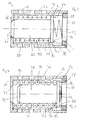
- eine Schnittansicht der erfindungsgemäßen Ventilanordnung in einer ersten Ventilstellung;
- Fig. 5
- eine der Fig. 4 entsprechende Ansicht der Ventilanordnung in einer zweiten Ventilstellung;
- Fig. 6
- eine der Fig. 4 enstprechende Ansicht der Ventilanordnung in einer dritten Ventilstellung;
- Fig. 7
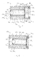
- eine Längsschnittansicht eines Ventilelements gemäß einer alternativen Ausgestaltungsform;
- Fig. 8
- das in Fig. 7 gezeigte Ventilelement in einer anderen Schaltstellung;
- Fig. 9
- eine Teil-/Querschnittansicht des Ventilelements der Fig. 7, geschnitten längs einer Linie VIIII-VIIII in Fig. 7;
- Fig. 10
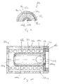
- eine weitere der Fig. 7 entsprechende Ansicht des Ventilelements in einer anderen Schaltstellung;
- Fig. 11
- eine Schnittansicht einer alternativen erfindungsgemäßen Ventilanordnung in einer ersten Ventilstellung;
- Fig. 12
- die Ventilanordnung der Fig. 11 in einer zweiten Ventilstellung;
- Fig. 13
- die Ventilanordnung der Fig. 11 in einer dritten Ventilstellung.
- Fig. 1
- a schematic view of a vehicle heating system, in which the invention can be realized;
- Fig. 2
- a longitudinal sectional view of an insertable in the valve assembly according to the invention valve element;
- Fig. 3
- a view corresponding to Figure 2 of the valve element in a different valve position.
- Fig. 4
- a sectional view of the valve assembly according to the invention in a first valve position;
- Fig. 5
- a view corresponding to Figure 4 of the valve assembly in a second valve position.
- Fig. 6
- FIG. 4 shows a corresponding view of the valve arrangement in a third valve position; FIG.
- Fig. 7
- a longitudinal sectional view of a valve element according to an alternative embodiment;
- Fig. 8
- the valve element shown in Figure 7 in another switching position.
- Fig. 9
- a partial / cross-sectional view of the valve element of Figure 7, taken along a line VIIII-VIIII in Fig. 7.
- Fig. 10
- a further of Figure 7 corresponding view of the valve element in another switching position.
- Fig. 11
- a sectional view of an alternative valve arrangement according to the invention in a first valve position;
- Fig. 12
- the valve assembly of Figure 11 in a second valve position.
- Fig. 13
- the valve assembly of FIG. 11 in a third valve position.
In Fig. 1 ist in prinzipieller Darstellung ein Fahrzeugheizsystem 10 gezeigt. Dieses Heizsystem 10 dient dazu, die in verschiedenen nachfolgend noch beschriebenen Systembereichen erzeugte Wärme einerseits von diesen Systembereichen abzuführen und andererseits zur Nutzung zur Erwärmung der in den Fahrzeuginnenraum einzuleitenden Luft oder zur anderweitigen Nutzung zur Verfügung zu stellen.In Fig. 1, a vehicle heating system 10 is shown in a schematic representation. This heating system 10 is used in various below described system areas generated heat on the one hand of these To dissipate system areas and on the other hand for use for heating the air to be introduced into the vehicle interior or otherwise To provide use.
Das Heizsystem 10 umfasst als erste Wärmequelle ein beispielsweise als
Brennkraftmaschine ausgebildetes Antriebsaggregat 12 und umfasst als
zweite Wärmequelle ein Zusatzheizgerät 14, das als Standheizung oder
insbesondere bei Turbodieselantriebsaggregaten als Zuheizer wirksam sein
kann. Durch ein allgemein mit 16 bezeichnetes Leitungssystem zirkuliert ein
im nachfolgenden als Heizfluid bezeichnetes flüssiges Medium, im
Allgemeinen Wasser. Dieses Heizfluid kann durch zwei Pumpen 18, 20 zur
Zirkulation im Leitungssystem 16 angetrieben werden. Die Pumpe 18 ist
beispielsweise im Bereich des Antriebsaggregats 12 oder
strömungstechnisch stromaufwärts davon angeordnet, während die Pumpe
20 im Heizgerät 14 oder strömungstechnisch stromaufwärts davon
angeordnet sein kann. Diese beiden Pumpen 18, 20 stehen
selbstverständlich unter der Ansteuerung einer Ansteuervorrichtung, ebenso
wie verschiedene andere anzusteuernde Systembereiche, wie
beispielsweise das Antriebsaggregat 12 oder ein Gebläse 22, das einem in
das Leitungssystem 16 integrierten Wärmetauscher 24 zugeordnet ist, um
bei Durchströmung des Wärmetauschers 24 mit erwärmtem Heizfluid diesen
Wärmetauscher 24 mit Luft zu umströmen.The heating system 10 includes, for example, as the first heat source
Internal combustion engine trained
Das Leitungssystem 16 umfasst ausgehend von dem Heizgerät 14 einen
Leitungsabschnitt 26, der in einen Leitungsabschnitt 26 übergeht. Dieser
Leitungsabschnitt 28 führt zu dem Wärmetauscher 24. In demjenigen Bereich,
in dem der Leitungsabschnitt 26 in den Leitungsabschnitt 28 übergeht
oder in diesen einmündet, führt ein weiterer Leitungsabschnitt 30 zu einer
nachfolgend detaillierter beschriebenen Ventilanordnung 32. Ein Leitungabschnitt
34 führt von dem Wärmetauscher 24 weg und teilt sich in einen zur
Pumpe 18 bzw. zum Antriebsaggregat führenden Leitungsabschnitt 36 und
einen zu einem Rückschlagventil 38 führenden Leitungsabschnitt 40 auf.
Das durch die Pumpe 18 bzw. über den Leitungsabschnitt 36 in das
Antriebsaggregat 12 eingeleitete Heizfluid verlässt das Antriebsaggregat 12
über einen Leitungsabschnitt 42 in Richtung zu der bereits angesprochenen
Ventilanordnung 32. Zwischen dem bereits angesprochenen Rückschlagventil
38 und der Ventilanordnung 32 liegt ein weiterer Leitungsabschnitt 44,
von dem ein Leitungsabschnitt 46 wegführt bzw. abgezweigt ist. Dieser
Leitungsabschnitt 46 führt zurück zum Heizgerät 14. The
Das Rückschlagventil 38 ist so in das Leitungssystem zwischen den
Leitungsabschnitten 40 und 44 eingegliedert, dass bei entsprechendem
Fluiddruck dieses vom Leitungsabschnitt 40 in den Leitungsabschnitt 44 gelangen
kann, jedoch nicht vom Leitungsabschnitt 44 in den Leitungsabschnitt
40 eintreten kann.The
Aus der vorangehenden Beschreibung erkennt man, dass die Ventilanordnung
32 grundsätzlich dazu vorgesehen ist, die drei Leitungsabschnitte 30,
42, 44 strömungsmäßig miteinander in Verbindung zu bringen, was nachfolgend
noch detaillierter beschrieben wird. Im Sinne der vorliegenden Erfindung
bildet dabei der Leitungsabschnitt 30 eine erste Leitung, der
Leitungsabschnitt 40 bildet eine zweite Leitung und der Leitungsabschnitt 44
bildet eine dritte Leitung.From the foregoing description, it can be seen that the
Die in Fig. 1 nur schematisch dargestellte Ventilanordnung wird nachfolgend mit Bezug auf die Figuren 2 bis 4 hinsichtlich ihres Aufbaus detaillierter erläutert. Dabei zeigt die Fig. 4 denjenigen Bereich, der in Fig. 1 in dem Kasten IV mit strichlierter Linie eingefasst ist.The valve arrangement shown only schematically in FIG. 1 will be described below with reference to Figures 2 to 4 in more detail with respect to their structure explained. In this case, Fig. 4 shows that area which in Fig. 1 in the Box IV is bordered by a dashed line.
Dabei erkennt man zunächst in Fig. 4, dass die beiden Leitungsabschnitte
30, 42, wie vorangehend bereits geschildert also die erste Leitung 30 und die
zweite Leitung 42, in einem gemeinsamen Rohrabschnitt 48 ausgebildet sein
können, der somit im Wesentlichen auch das Gehäuse 50 der Ventilanordnung
42 bereitstellt. Von diesem Rohrabschnitt 48 zweigt dann ein weiterer
Rohrabschnitt 52 ab, der im Wesentlichen dann den Leitungsabschnitt
44 bereitstellt. In dem Rohrabschnitt 48 sind zwei hülsenartige Einsatzteile
54, 56 angeordnet, die in Längsrichtung des Rohrabschnitts 48 einen
gegenseitigen Abstand aufweisen und somit einen Raumbereich 58 im
Rohrabschnitt 48 definieren, in dem ein nachfolgend detaillierter beschriebenes
Ventilelement 60 in der Längsrichtung des Rohrabschnitts 48
zwischen den beiden Einsätzen 54, 56, die als Bewegungsanschläge für das
Ventilelement 60 wirken, hin- und herbewegbar ist. Dieses insbesondere in
der Fig. 2 detaillierter erkennbare Ventilelement 60 umfasst ein zylinder-bzw.
hülsenartig ausgestaltetes erstes Ventilorgan 62, das bei der vorangehend
beschriebenen Hin- und Herbewegung im Wesentlichen als Ventilschieber
wirksam ist. Im Innenraum dieses ersten Ventilorgans 62 ist eine
Ventilkammer 64 gebildet. An den beiden in der Bewegungsrichtung gelegenen
Enden ist dieses Ventilorgan 62 durch eine Bodenwandung 66 bzw.
ein scheibenartiges Einsatzteil 68 begrenzt bzw. abgeschlossen. In dem Einsatzteil
68 ist eine Öffnung 70 ausgebildet, die zur Ventilkammer 64 hin offen
ist und die, wie in der Fig. 4 erkennbar, im Wesentlichen zum Leitungsabschnitt
30 hin, also zur ersten Leitung hin, orientiert ist. In der Bodenwandung
66 ist eine weitere Öffnung 72 vorgesehen, die, wie ebenfalls in
Fig. 4 erkennbar, bei entsprechender Positionierung des Ventilelements 60
im Wesentlichen zum Leitungsabschnitt 42 hin, also zur zweiten Leitung hin,
offen ist. In der im Wesentlichen zylindrischen Umfangswandung 74 des
ersten Ventilorgans 62 sind weiterhin mehrere Öffnungen 76 vorgesehen,
über welche bei entsprechender Positionierung des Ventilelements 60, wie
sie in Fig. 4 gezeigt ist, die Ventilkammer 64 in Richtung zum Leitungsabschnitt
44 hin offen ist. Diejenigen der Öffnungen 76, die nicht im Mündungsbereich
des Rohrabschnitts 52 positioniert sind, sind im Wesentlichen durch
den Rohrabschnitt 48 überdeckt und durch die vergleichsweise enge, jedoch
eine Verschiebebewegung des ersten Ventilorgans 62 zulassende Passung
des Ventilelements 60 in dem Rohrabschnitt 48 gegen Fluidaustritt im
Wesentlichen abgeschlossen.It can be seen first in Fig. 4, that the two
In der Ventilkammer 64 des ersten Ventilorgans 62 ist ein zweites Ventilorgan
78 aufgenommen. Dieses zweite Ventilorgan 78 ist im ersten Ventilorgan
62 in dessen Verschieberichtung, also in der Längsrichtung des
Rohrabschnitts 48, bewegbar. Das Ventilorgan 78 weist einen in dieser Bewegungsrichtung
langgestreckten Schaftbereich 80 auf, der im Bereich seines
freien Endes 82 so ausgebildet ist, dass er bei entsprechender Positionierung
die Öffnung 72 in der Bondewandung 66 abschließen kann. Hier
kann beispielsweise sowohl im Bereich der Öffnung 72 als auch im Bereich
des freien Endes 82 des Schaftbereichs 80 eine kegelstumpfartige Ausgestaltung
gewählt werden. In seinem anderen Endbereich 84 ist das zweite
Ventilorgan 78 mit einem radial vorspringenden Flanschbereich 86 ausgebildet.
An diesem Flanschbereich 86 sind einerseits Abstandselemente 88
vorgesehen, die bei der in Fig. 3 erkennbaren Positionierung des zweiten
Ventilorgans 78 in der Ventilkammer 64 dafür sorgen, dass der Flanschbereich
86 einen Abstand zu dem Einsatzteil 68 aufweist und somit die Öffnung
70 nicht vollständig abschließen kann. Auch bei der in Fig. 3 erkennbaren
Positionierung ist somit eine Strömungsverbindung zwischen der Öffnung 70
und der Ventilkammer 64 realisiert, wobei dies in der in Fig. 3 erkennbaren
Positionierung des zweiten Ventilorgans eine Minimalströmungsverbindung
ist.In the
Den Schaftbereich 80 des zweiten Ventilorgans 78 umgebend ist in der
Ventilkammer 64 ein Stellelement 90 vorgesehen. Dieses hier schraubenartig
gewunden ausgestaltete Stellelement 90 ist thermisch aktiv, d.h., ändert
temperaturabhängig seine Abmessung in der Bewegungsrichtung des
zweiten Ventilorgans 78 im ersten Ventilorgan 62. Hier kann beispielsweise
ein schraubenartig gewundenes Bauteil aus einem Formgedächtnismaterial
eingesetzt werden, das unter einer bestimmten Schalttemperatur die in Fig. 2
erkennbare minimale Längenausdehnung aufweist und über dieser
Schalttemperatur die in Fig. 3 dargestellte vergrößerte Längenausdehnung
aufweist. Durch Veränderung der Temperatur im Bereich dieses
Stellelements 90 kann also das zweite Ventilorgan 78 in der Ventilkammer
64 verschoben werden, wobei diese Verschiebung bei Erhöhung der Temperatur
entgegen der Rückstellwirkung einer Vorspannfeder 92 erfolgt. Diese
stützt sich am ersten Ventilorgan 62 im Bereich des Einsatzteils, 68 einerseits
und am zweiten Ventilorgan 78 im Bereich des Endbereichs 84 desselben
andererseits ab. Eine Temperaturabnahme im Bereich des Stellorgans, die
eine entsprechende Kontraktion desselben bewirkt, hat dann zur Folge, dass
das zweite Ventilorgan 78 der Vorspannwirkung der Rückstellfeder 92
folgend von der in Fig. 3 erkennbaren Positionierung in die in Fig. 2
erkennbare Positionierung gelangt, in welcher die Öffnung 72 im Wesentlichen
vollständig abgeschlossen ist. The
Man erkennt in den Fig. 2 und 3 weiter, dass an der Innenseite der zylindrischen
Wandung 64 des ersten Ventilorgans 62 mehrere in der
Längsrichtung dieses Ventilorgans 62 sich erstreckende rippenartige Vorsprünge
94 vorgesehen sind. Zwischen den in Umfangsrichtung aufeinander
folgenden Vorsprüngen 94 sind Strömungsaussparungen 96 gebildet. Durch
diese Vorsprünge 94 wird einerseits eine definierte Führung des zweiten
Ventilorgans 78 bzw. des Stellelements 90 in dem ersten Ventilorgan 62 gewährleistet.
Andererseits hat das Bereitstellen der Aussparungen 96 zur
Folge, dass die Öffnungen 76, je nach Positionierung des zweiten Ventilorgans
78 über die Ventilkammer 64 in Strömungsverbindung mit der Öffnung
70 bzw. der Öffnung 72 stehen können.It can be seen in Figs. 2 and 3 further that on the inside of the
Nachfolgend wird auch unter weitergehende Bezugnahme auf die Figuren 5 und 6 die Funktionsweise der vorangehend detailliert beschriebenen Ventilanordnung 32 bei Eingliederung derselben in das Heizsystem 10 der Fig. 1 beschrieben.Hereinafter, with further reference to the figures 5 and Figure 6 illustrates the operation of the valve assembly described in detail above 32 upon incorporation thereof into the heating system 10 of FIG. 1 described.
Es sei zunächst angenommen, dass das Heizsystem 10 im Kaltzustand in
Betrieb gesetzt werden soll und zwar dadurch, dass das Heizgerät 14 zum
Vorkonditionieren eines Fahrzeugs aktiviert wird. D.h., durch im Heizgerät 14
ablaufende Verbrennung wird Wärme erzeugt, und durch Betreiben der
Pumpe 20 wird das Heizfluid durch das Heizgerät 14 geleitet und dabei
erwärmt. Dabei strömt das Heizfluid in der in Fig. 1 beim Heizgerät 14 eingezeichneten
Strömungsrichtung. In diesem Zustand, in dem das Antriebsaggregat
12 noch nicht betrieben werden soll, bleibt die Pumpe 18 außer
Betrieb. Das Heizfluid, das in dem Heizgerät 14 Wärme aufgenommen hat,
strömt also zunächst in den Leitungsabschnitt 26 und von diesem in Richtung
zu den Leitungsabschnitten 28, 30. Dabei wird, wie in Fig. 4 veranschaulicht,
im Leitungsabschnitt 30 ein Druck P1 aufgebaut. Dieser Druck
P1 ist zunächst größer, als der im Leitungsabschnitt 42 vorherrschende
Druck P2, da durch die Pumpe 18 kein Fluid in Richtung Leitungsabschnitt
42 gefördert wird. Dies hat zur Folge, dass durch die Druckdifferenz P1-P2
das Ventilelement 60 in dem Raumbereich 58 so verschoben wird, dass es
in die in Fig. 4 erkennbare erste Verbindungsstellung gelangt. In dieser
ersten Verbindungsstellung ist die Leitungsverbindung zwischen den beiden
Leitungsabschnitten 42, 44. zunächst unterbrochen, während über die
Öffnung 70 über die Ventilkammer 64 und die zum Leitungsabschnitt 44 hin
frei liegenden Öffnungen 76 der Leitungsabschnitt 30 in
Strömungsverbindung mit dem Leitungsabschnitt 44 steht. Da weiterhin zu
diesem Zeitpunkt das geförderte Heizfluid eine vergleichsweise niedrige
Temperatur aufweisen wird, wird das Stellelement 90 sich zusammenziehen
bzw. seinen zusammengezogenen Zustand beibehalten, so dass das zweite
Ventilorgan 78, wie in Fig. 4 erkennbar, den Strömungsweg zwischen den
beiden Leitungsabschnitten 30, 44 freigibt, d.h. beispielsweise in maximal
möglichem Ausmaß freigibt. In diesem Zustand strömt also das von der
Pumpe 20 in den Leitungsabschnitt 26 geförderte Heizfluid einerseits über
den Leitungsabschnitt 28 zum Wärmetauscher 24 und andererseits über den
Leitungsabschnitt 30 und die Ventilanordnung 32 in den Leitungsabschnitt
44. Das in den Leitungsabschnitt 44 geförderte Heizfluid kann auf Grund der
Wirkung des Rückschlagventils 38 nicht in den Leitungsabschnitt 40
eintreten und wird somit über den Leitungsabschnitt 46 zum Heizgerät 14
zurückgefördert. Das in Richtung zum Wärmetauscher 24 geförderte
Heizfluid tritt nach Durchströmen des Wärmetauschers 24 in den
Leitungsabschnitt 34 ein. Da in diesem Zustand der Leitungsabschnitt 42
durch das Ventilelement 60 im Wesentlichen vollständig gegen
Durchströmung abgeschlossen ist, kann das den Wärmetauscher 24 über
den Leitungsabschnitt 34 verlassende Heizfluid nicht über den
Leitungsabschnitt 36 in das Antriebsaggregat 12 gelangen. Vielmehr wird
dieses Fluid in den Leitungsabschnitt 40 eintreten, über das Rückschlagventil
38 in den Leitungsabschnitt 44 gelangen und sich dort mit dem
aus der Ventilanordnung 32 in den Leitungsabschnitt 44 eintretenden Heizfluid
vermischen und über den Leitungsabschnitt 46 zum Heizgerät 14 zurückströmen.It is first assumed that the heating system 10 in the cold state in
Operation is to be set by the fact that the
In der Anfangsphase, in welcher das in dem vorangehend beschriebenen
"kleinen" Kreislauf zirkulierende Heizfluid noch eine vergleichsweise niedrige
Temperatur haben wird, ist, bedingt durch die Kontraktion des Stellorgans
90, das zweite Ventilorgan 68 in einer ersten Überbrückungsstellung, die in
Fig. 4 erkennbar ist. Wie bereits ausgeführt, wird in der ersten Überbrückungsstellung
die Öffnung 72, die ansonsten in Richtung zum Leitungsabschnitt
42 hin offen wäre, abgeschlossen, und zwar vorzugsweise vollständig
abgeschlossen, während das Ventilelement 60 eine Überbrückung
zwischen den beiden Leitungsabschnitten 30 und 44 realisiert. In diesem
Zustand durchströmt das Heizfluid auch die Ventilkammer 64, so dass insbesondere
durch Bereitstellung der in den Figuren 2 und 3 erkennbaren
Aussparungen 96 auch das Stellelement 90 in Kontakt mit diesem Heizfluid
kommen wird und somit dessen Temperatur sensieren wird.In the initial phase, in which that in the previously described
"small" circulation circulating heating fluid still a comparatively low
Temperature is due to the contraction of the
Nimmt nach einiger Betriebszeit durch kontinuierliche Wärmeaufnahme die
Temperatur des zirkulierenden Heizfluids zu, so wird dies das Stellelement
90 durch seinen vorangehend beschriebenen thermischen Kontakt mit dem
zirkulierenden Fluid erfassen. Eine Temperaturzunahme hat zur Folge, dass
das Stellelement 90 seine Längenabmessung ändern wird und das zweite
Ventilorgan 78 mit einer Kraft beaufschlagen wird, die die Rückstellkraft der
Feder 92 überkompensiert. Dies hat zur Folge, dass mit ansteigender Temperatur
das zweite Ventilorgan 78 im ersten Ventilorgan 62 aus der in Fig. 4
erkennbaren ersten Überbrückungsstellung in Richtung zu einer in Fig. 5 erkennbaren
zweiten Überbrückungsstellung verschoben wird. Dieser Übergang
kann spontan erfolgen, also insbesondere bei Einsatz eines Formgedächtnislementes
dann erfolgen, wenn die Schalttemperatur dieses Stellelements
90 überschritten wird. Grundsätzlich ist es auch möglich, dass auf
Grund der Tatsache, dass nicht alle Bereiche des Stellelements 90 gleichermaßen
mit dem zirkulierenden Heizfluid umströmt werden, zunächst diejenigen
Bereiche einen Temperaturanstieg erfahren bzw. sensieren werden,
die stärker in thermischem Kontakt mit dem Heizfluid stehen. D.h., es kann
auch nur eine lokale Längenzunahme des Stellelements 90 erfolgen, so
dass dieses nicht digital zwischen dem ersten Überbrückungzustand der Fig.
4 und dem zweiten Überbrückungszustand der Fig. 5 umschaltet, sondern
mit einer allmählich ansteigenden Temperatur das zweite Ventilorgan 78
auch allmählich zunhemend in Richtung zur zweiten Überbrückungsstellung
verschoben wird.Takes after some operating time by continuous heat absorption the
Temperature of the circulating heating fluid, so this is the actuator
90 through its previously described thermal contact with the
detect circulating fluid. A temperature increase has the consequence that
the
Bei diesem Übergang in die zweite Überbrückungsstellung wird spontan oder
allmählich zunehmend die Öffnung 72 im ersten Ventilorgan 62 freigegeben,
während der Strömungsweg von der Öffnung 70 zu den Öffnungen 76
allmählich gedrosselt wird. Bei Positionierung des zweiten Ventilorgans 78 in
dem in Fig. 5 erkennbaren zweiten Überbrückungszustand ist dann eine
Strömungsverbindung zwischen dem Leitungsabschnitt 42 und dem
Leitungsabschnitt 44 über die Öffnung 72, die Ventilkammer 74 und die Öffnungen
76 in maximalem Ausmaß realisiert, während über die Öffnung 70 zu
den Öffnungen 76 auf Grund der Abstandshalter 88 eine im Vergleich zu
dem Zustand der Fig. 4 gedrosselte Minimalströmung möglich ist.In this transition to the second bridging position is spontaneous or
gradually the
In dem in Fig. 5 erkennbaren zweiten Überbrückungszustand des zweiten
Ventilorgans 78 ist nunmehr also der Strömungsweg vom Leitungsabschnitt
42 zum Leitungsabschnitt 44 freigegeben. Die Folge davon ist, dass auch bei
noch nicht betriebener Pumpe 18 und in Folge der nach wie vor unveränderten
Druckverhältnisse P1, P2 das Ventilelement 60 grundsätzlich in
seiner ersten Verbindungsstellung verbleibt, trotzdem aber nunmehr eine
Durchströmung des Antriebsaggregats 12 möglich ist. D.h., das von dem
Wärmetauscher 24 unter der Förderwirkung der Pumpe 20 in den Leitungsabschnitt
34 geförderte Heizfluid wird nunmehr auch in den Leitungsabschnitt
36 eintreten können und nach Durchströmen des Antriebsaggregats
über den Leitungsabschnitt 42 im Wesentlichen in den Leitungsabschnitt 44
eintreten können. Somit wird im Leitungsabschnitt 44 ein Druck aufgebaut,
der das Öffnen des Rückschlagventils 38 erschwert, so dass im Wesentlichen
kein Fluid mehr in den Leitungsabschnitt 40 und von dort in den
Leitungsabschnitt 44 strömen wird.In the second bridging state of the second recognizable in
In diesem Betriebszustand, in dem also das von dem Heizgerät 14 in den
Leitungsabschnitt 26 und von diesem in die Leitungsabschnitte 28, 30 abgegebene
Heizfluid eine bestimmte höhere Temperatur erreicht hat, wird
Wärme nicht nur im Bereich des Wärmetauschers 24 abgegeben, sondern
es wird zusätzlich auch Wärme im Bereich des Antriebsaggregats 12
abgegeben, so dass dieses vorerwärmt werden kann. In diesem Betriebszustand,
in dem das erste Ventilorgan 62 in seiner ersten Ventilstellung ist und
das zweite Ventilorgan 78 in seiner zweiten Überbrückungsstellung ist. Auf
Grund der Tatsache, dass der Druck P1 auch in dieser Phase größer sein
wird, als der Druck P2, wird nunmehr ein Teil des Heizfluids über den
Leitungsabschnitt 30 in die Ventilkammer 64 eintreten. Auf Grund der
Tatsache, dass die Öffnungen 76 einen größeren Strömungswiderstand
darstellen, als die Öffnung 72, wird der größere Teil dieses Fluidanteils in
den Leitungsabschnitt 42 eintreten und nunmehr das Antriebsaggregat 12
durchströmen, und zwar in einer Strömungsrichtung, die der unter
Förderwirkung der Pumpe 18 an sich vorhandenen Strömungsrichtung
entgegengesetzt ist. Dieser Heizfluidanteil wird sich, nachdem er in den
Leitungsabschnitt 36 eingetreten ist, mit dem aus dem Leitungsabschnitt 34
heranströmenden Heizfluidanteil vereinigen und über den Leitungsabschnitt
40 und das Rückschlagventil 38 zurückströmen.In this operating state, in which that of the
Da in diesem Zustand nach wie vor das Heizgerät 14 die einzige Wärmequelle
ist, kann nunmehr der Fall auftreten, dass durch zusätzliche Wärmeabgabe
im Bereich des Antriebsaggregats 12 das in den Leitungsabschnitt
42 gelangende Heizfluid eine Temperatur aufweist, die beispielsweise unter
der Schalttemperatur des aus Formgedächtnismaterial aufgebauten Stellelements
90 liegt, bzw. die eine Kontraktion des diese Temperatur nunmehr
sensierenden Stellelements 90 zur Folge haben wird. Daraus resultiert durch
die Kontraktion des Stellelements 90, dass das zweite Ventilorgan 78 sich
nunmehr der Vorspannwirkung der Feder 92 folgend zurück in Richtung zur
ersten Überbrückungsstellung bewegen wird. Dieser Übergang kann wieder
spontan auftreten, kann aber vor allem dann, wenn das Stellelement 90 nicht
in seinem gesamten Längenbereich gleichmäßig in Kontakt mit dem
sensierten Heizfluid ist, auch allmählich stattfinden, da nur gewisse Bereiche
des Stellelements 90 sich zunächst zusammenziehen werden. Since in this state, the
Die Folge dieses Zurückverstellens des zweiten Ventilorgans 78 in seine
erste Überbrückungsstellung ist, dass nunmehr der Strömungsweg über das
Antriebsaggregat 12 wieder abgesperrt bzw. zumindest gedrosselt wird, so
dass ein größerer Anteil des Heizfluids wieder unter Auslassung des Antriebsaggregats
über den Leitungsabschnitt 40 direkt zum Heizgerät 14 zurückströmen
wird.The consequence of this back adjustment of the
Man erkennt aus der vorangehenden Beschreibung, dass in dieser Phase, in
welcher das Heizgerät 14 im Wesentlichen die einzige Wärmequelle bildet,
die Ventilanordnung 32 eine Thermostatfunktion erfüllt, obgleich, bedingt
durch die Druckverhältnisse, das erste Ventilorgan 62 in seiner ersten Verbindungsstellung
verbleibt. Es kann somit sichergestellt werden, dass das
über den Wärmetauscher 24 zirkulierende Heizfluid eine näherungsweise
gleichbleibende Temperatur beibehält, da es bei übermäßiger Erwärmung
einen zusätzlichen Wärmeanteil im Antriebsaggreggat 12 abgeben kann, bei
unter eine bestimmte Grenze fallender Temperatur jedoch eine zur übermäßigen
Abkühlung führende Wärmeabgabe im Antriebsaggregat vermieden
bzw. zumindest gemindert wird. Letztendlich kann bei entsprechender Auswahl
des Stellelements 90 dafür gesorgt werden, dass temperaturabhängig
das zweite Stellorgan einen Gleichgewichtszustand zwischen der ersten
Überbrückungsstellung und der zweiten Überbrückungsstellung einnehmen
kann, so dass bei Betreiben des Heizgeräts 14 mit einer vorbestimmten
Heizleistung immer so viel Heizfluid über das Antriebsaggregat 12 strömen
und dort Wärme abgeben kann, wie dies erforderlich ist, um die Temperatur
des zirkulierenden Heizfluids auf einem gewünschten Niveau zu halten. Bei
einem stark ausgeprägten Schaltverhalten wird dieser Zustand eines gewünschten
Temperaturniveaus bei dem zirkulierenden Heizfluid durch alternierendes
Zu- bzw. Abschalten des Strömungswegs über das Antriebsaggregat
12 erlangt.It can be seen from the foregoing description that at this stage, in
which
Wird das Antriebsaggregat 12 in Betrieb genommen, so wird im Allgemeinen
auch die Pumpe 18 aktiviert, um auf diese Art und Weise für eine ausreichende
Wärmeabfuhr der im Betrieb des Antriebsaggregats 12 dort entstehenden
Wärme durch entsprechende Durchströmung vermittels des hier
als Kühlmittel wirksamen Heizfluids zu sorgen. Dies hat zur Folge, dass ein
Betriebszustand auftreten wird oder auftreten kann, in dem gleichzeitig die
beiden Pumpen 18 und 20 betrieben werden und gleichzeitig auch im
Bereich des Antriebsaggregats 12 als erste Wärmequelle und des Heizgeräts
14 als zweite Wärmequelle Wärmeenergie zur Übertragung auf das
im Leitungssystem 16 zirkulierende Heizfluid bereitgestellt wird. Das Fördervermögen
der beiden Pumpen 18, 20 bzw. auch die Leitungsquerschnitte
sind bei dem System 10 so aufeinander abgestimmt, dass auch dann, wenn
die Pumpe 20 betrieben wird und im Leitungsabschnitt 30 somit ein entsprechend
hoher Druck P1 generiert wird, der durch Betreiben der Pumpe 18 im
Leitungsabschnitt 42 bereitgestellte Druck P2 den Druck P1 überwiegt. Die
Folge davon ist, dass nunmehr das erste Ventilorgan 62 mit dem darin aufgenommenen
zweiten Ventilorgan 78, also das gesamte Ventilelelement 60,
aus seiner in den Figuren 4 und 5 erkennbaren ersten Verbindungsstellung
in eine in der Fig. 6 erkennbare zweite Verbindungsstellung verschoben wird.
In dieser zweiten Verbindungsstellung überdeckt das erste Ventilorgan 62
die Einmündung des Rohrabschnitts 52 in den Rohrabschnitt 48 praktisch
nicht mehr, so dass nunmehr eine Strömungsverbindung zwischen dem
Leitungsabschnitt 42 und dem Leitungsabschnitt 44 bereitgestellt ist. Das
unter der Förderwirkung der Pumpe 18 und auch ggf. der Förderwirkung der
Pumpe 20 über den Leitungsabschnitt 20 zum Wärmetauscher 24 und von
diesem in den Leitungsabschnitt 34 geförderte Heizfluid strömt nunmehr
auch durch die Saugwirkung der Pumpe 18 über den Leitungsabschnitt 36,
durch das Antriebsaggregat 12 hindurch und in den Leitungsabschnitt 42. Ist
das Antriebsaggregat 12 eben erst in Betrieb genommen worden, so kann in
dieser Phase durch das im Heizgerät 14 erwärmte Heizfluid noch Wärme auf
das Antriebsaggregat 12 übertragen werden. Ist das Antriebsaggregat bereits
länger in Betrieb, so wird die dort dann anfallende Wärme auf das Heizfluid
übertragen und vom Antriebsaggregat 12 abgeführt.If the
Das in den Leitungsabschnitt 42 geförderte Heizfluid strömt dann in den
Leitungsabschnitt 44 und von diesem auf Grund der Sperrwirkung des Rückschlagventils
38 in den Leitungsabschnitt 46. Vom Leitungsabschnitt 46
strömt dieses Heizfluid dann durch die Pumpe 20 des Heizgeräts 14 in den
Leitungsabschnitt 26 und von diesem erneut über den Leitungsabschnitt 28
zum Wärmetauscher 24.The heating fluid delivered into the
Da in dieser Phase das Heizfluid im Allgemeinen eine höhere Temperatur
aufweisen wird, ist davon auszugehen, dass das zweite Ventilorgan in seiner
zweiten Überbrückungsstellung ist, in welcher die Öffnung 72 freigegeben ist
und auf Grund des Vorhandenseins der Abstandshalter 88 auch die Öffnung
70 nicht vollständig abgeschlossen ist. D.h., zumindest ein Teil des über den
Leitungsabschnitt 42 herangeförderten Heizfluids durchströmt das erste
Ventilorgan 62 bzw. das Ventilelement 60 und gelangt auf diese Art und
Weise, ohne über das Heizgerät 14 geströmt zu sein, in den Leitungsabschnitt
30 und den Leitungsabschnitt 28. Auf diese Art und Weise kann der
Gesamtströmungswiderstand des Leitungssystems 16 reduziert werden.
Dies ist vor allem dann von Bedeutung, wenn beispielsweise auf Grund nicht
mehr erforderlichen Betriebs des Heizgeräts 14 auch die diesem zugeordnete
Pumpe 20 nicht mehr betrieben wird und somit das unter der
Förderwirkung der Pumpe 18 dann noch zirkulierende Heizfluid zwar über
die Leitungsabschnitte 44, 46 in das Heizgerät 14 bzw. die Pumpe 20 gefördert
wird, diese Pumpe 20 aber nur auf Grund der Förderwirkung der
Pumpe 18 durchströmen kann. In diesem Zustand stellt, je nach Bauart, die
Pumpe 20 einen vergleichsweise großen Strömungswiderstand dar.Since in this phase, the heating fluid is generally a higher temperature
will assume that the second valve member in his
second lock-up position is, in which the
Die vorangehend beschriebene erfindungsgemäße Ventilanordnung ist von
sehr einfachem Aufbau und weist insbesondere auch zum Bereitstellen der
vorangehend beschriebenen Thermostatfunktion nur eine vergleichsweise
geringe Anzahl an Bauteilen auf. Von besonderer Bedeutung ist auch, dass
die erfindungsgemäße Ventilanordnung 32 in konstruktiver Hinsicht ohne
Weiteres so ausgeführt werden kann, dass sie in übliche Heizsysteme in
baulicher Art und Weise integriert werden kann, da sie im Wesentlichen nur
die durch den Rohrabschnitt 48 bereitgestellten Leitungsabschnitte 30, 42
bzw. entsprechende Anschlussmöglichkeiten dafür sowie den durch den
Rohrabschnitt 52 bereitgestellten Leitungsabschnitt 44 bzw. eine entsprechende
Anschlussmöglichkeit für diesen aufweisen muss.The above-described valve arrangement according to the invention is of
very simple structure and has in particular also for providing the
previously described thermostat function only a comparatively
low number of components. Of particular importance is that
the
Mit Bezug auf die Figuren 7 bis 13 wird nachfolgend eine alternative Ausgestaltungsform einer erfindungsgemäßen Ventilanordnung beschrieben. Komponenten, welche vorangehend beschriebenen Komponenten hinsichtlich Aufbau bzw. Funktion entsprechen, sind mit dem gleichen Bezugszeichen unter Hinzufügung des Anhangs "a" bezeichnet.With reference to FIGS. 7 to 13, an alternative embodiment will be described below a valve assembly according to the invention described. Components which components described above in terms Structure or function correspond, are denoted by the same reference numerals with the addition of Annex "a".
Zunächst sei mit Bezug auf die Figuren 7 bis 10 das Ventilelement 60a
dieser Ausgestaltungsform beschrieben. Man erkennt wieder das zylinderartig
bzw. topfartig ausgebildete erste Ventilorgan 62a mit seiner zylindrischen
Wandung 74a und dem Bondenbereich 66a. In dem Bodenbereich
66a ist wieder die Öffnung 72a ausgebildet. Andernends ist das erste
Ventilorgan 62a bzw. die darin ausgebildete Ventilkammer 64a durch das
Einsatzteil 68a mit der darin ausgebildeten Öffnung 70a begrenzt. In der Zylinderkammer
64a ist das zweite Ventilorgan 78a wieder unter der Krafteinwirkung
des Stellelements 90a bzw. der Rückstellfeder 92a in der Richtung
der Längsachse des Ventilelements 60a temperaturabhängig verschiebbar.First, referring to Figs. 7 to 10, the
Das zweite Ventilorgan 78a ist bei dieser Ausgestaltungsform hohl ausgestaltet
und weist einen Innenraum 100a auf. Dieser Innenraum 100a ist im
Endbereich 82a durch eine Bodenwandung 102a begrenzt, in welcher
Bodenwandung 102a wiederum eine Öffnung 104a ausgebildet ist. Im
anderen Endbereich ist dieser Innenraum 100a durch ein Einsatzteil 106a
begrenzt, das einen ringförmigen Einpassabschnitt 108a und darin eine
sternartige Halteanordnung 110a aufweist. Mit dem Einpassabschnitt 108a
ist das Einsatzteil 106a in den flanschartigen Endbereich 86a des zweiten
Ventilorgans 78a fest eingesetzt. Weiter ist in dem Innenraum 100a ein
kugelartig ausgebildetes drittes Ventilorgan 112a aufgenommen. Dieses
kann sich entlang des Schaftabschnitts 80a des Ventilorgans 78a bewegen.
In der in Fig. 7 erkennbaren Bewegungsendstellung verschließt dieses
Ventilorgan 112a die Öffnung 104a beispielsweise vollständig. In der in Fig.
10 erkennbaren zweiten Bewegungsendstellung liegt das kugelartige Ventilorgan
112a an dem Einsatzteil 106a an, ist jedoch am Herausbewegen aus
dem Innenraum 100a gehindert. Gleichwohl ist durch mehrere auch das
kugelartige Ventilorgan 112a in seiner Bewegung führende und an der
Innenseite des Schaftabschnitts 80a in dessen Längsrichtung sich
erstreckende Vorsprünge 114a bzw. dazwischen gebildete Aussparungen
116a bei der in Fig. 10 dargestellten Endstellung des Ventilorgans 112a
dafür gesorgt, dass ein Fluiddurchtritt durch das zweite Ventilorgan 78a
möglich ist, d.h., eine Strömungsverbindung von der Öffnung 104a über den
Innenraum 100a durch eine Öffnungsanordnung 118a im Einsatzteil 106a
hindurch geschaffen ist.The
Die Funktionsweise einer mit einem derartigen Ventilorgan 60a ausgestatteten
Ventilanordnung 32a wird nachfolgend mit Bezug auf die Figuren 11 bis
13 beschrieben. In Fig. 11 ist der vorangehend mit Bezug auf die erste Ausgestaltungsform
bereits beschriebene und in der Fig. 4 erkennbare Betriebszustand
dargestellt. Das erste Ventilorgan 62a bzw. das Ventilelement 60a
ist in der ersten Verbindungsstellung. Die Öffnung 72a ist durch das zweite
Ventilorgan 78a abgeschlossen, während die Öffnung 70a freigegeben ist
und somit über die Ventilanordnung 64a eine Verbindung zu den Öffnungen
76a geschaffen ist. Somit kann unter der Förderwirkung der Pumpe 20 des
Heizgeräts 14 das in den Leitungabschnitt 30a eingetretene. Fluid das erste
Ventilorgan 62a durchströmen und in den Leitungsabschnitt 44a eintreten.
Dieser Kreislauf, der letztendlich nicht zur Erwärmung irgendwelcher Fahrzeugsystembereiche
beiträgt, dient zur Sensierung der Temperatur des ansonsten
in Richtung Wärmetauscher zirkulierenden Heizfluids, da auch bei
dieser Ausgestaltungsform in der ersten Vebindungsstellung und bei in der
ersten Überbrückungsstellung positioniertem Ventilorgan 78a das Steilelement
90a in im Wesentlichen von dem über den Leitungsabschnitt 30a
herangeförderten Fluid umströmt wird und somit dessen Temperatur
sensiert.The operation of a equipped with such a
Weiterhin erkennt man in Fig. 11, dass auf Grund der Tatsache, dass der
Druck P1 im Leitungsabschnitt 30a den Druck P2 im Leitungsabschnitt 42a
übersteigt, das dritte Ventilorgan 112a auch so positioniert ist, dass es die
Öffnung 104a im zweiten Ventilorgan 78a abschließt, so dass eine Durchströmbarkeit
des zweiten Ventilorgans 78a hier nicht gegeben ist.Furthermore, it can be seen in Fig. 11 that due to the fact that the
Pressure P1 in the
Bei Anstieg der Temperatur des Heizfluids findet dann bei weiterhin in der
ersten Verbindungsstellung bleibendem ersten Ventilorgan 62a eine Verschiebung
des zweiten Ventilorgans 78a in Richtung zu seiner zweiten Überbrückungsstellung
statt. In diesem Zustand ist dann die Öffnung 72a im
ersten Ventilorgan 60a freigegeben, so dass nunmehr eine Strömungsverbindung
zwischen dem Leitungsabschnitt 42a und dem Leitungsabschnitt
44a realisiert ist. Da unter der Krafteinwirkung des Stellelements 90a das
zweite Ventilorgan 78a mit seinem Flanschbereich 86a bei dieser Ausgestaltungsvariante
am Einsatzteil 68a aufsitzt, ist die Öffnung 70a im Einsatzteil
68a blockiert, auch deshalb, da weiterhin durch die Druckdifferenz P1 >
P2 das dritte Ventilorgan 112a die ihm zugeordnete Öffnung 104a im zweiten
Ventilorgan 78a sperrt und dieses somit gegen Durchströmung blockiert.
D.h. der vorangehend bei der ersten Ausgestaltungsform in diesem Zustand
noch mögliche geringe Strömungsanteil vom Leitungsabschnitt 30 in den
Leitungsabschnitt 44 bei in der zweiten Überbrückungsstellung positioniertem
zweiten Ventilorgan ist hier nicht vorhanden. Die Folge davon ist,
dass das Stellelement 90a hier ausschließlich von dem aus dem Leitungsabschnitt
42a heranströmenden Heizfluid umströmt wird und somit verstärkt
dessen Temperatur sensiert.As the temperature of the heating fluid increases then continues in the
first connection position remaining
Wird dann zusätzlich oder als alleiniges Förderorgan die in der Fig. 1 erkennbare
Pumpe 18 in Betrieb gesetzt, so wird wieder der Zustand auftreten,
in dem der Druck P2 den Druck P1 übersteigt. Die Folge davon ist, dass, wie
in Fig. 13 erkennbar, das erste Ventilorgan 62a bzw. das Ventilelement 60 in
seine zweite Verbindungsstellung gelangt, in welchem es die Einmündung
des Leitungsabschnitts 44a im Wesentlichen nicht mehr überdeckt. Es ist
dann eine Maximalströmungsverbindung zwischen dem Leitungsabschnitt
42a und dem Leitungsabschnitt 44a realisiert. Is then additionally or as the only conveying member recognizable in FIG. 1
Auf Grund der Tatsache, dass der Druck P2 nunmehr den Druck P1 übersteigt,
ist in diesem Zustand auch keine Kraft mehr vorhanden, die das dritte
Ventilorgan 112a auf seinem Ventilsitz, nämlich dem Bodenbereich 102a.
D.h., dass dritte Ventilorgan 112a wird sich in den Endbereich 84a des
ersten Ventilorgans 78a bewegen und die Öffnung 104a freigeben. Die Folge
davon ist, dass nunmehr das unter Druck aus dem Leitungsabschnitt 42a
ausströmende Heizfluid durch die Öffnung 72a in die Ventilkammer 64a
gelangen wird, durch die Öffnung 104a in den Innenraum 100a des zweiten
Ventilorgans gelangen wird und durch die Öffnungsanordnung 118a und die
Öffnung 70a in den Leitungsabschnitt 30 eintreten wird. Somit ist auch bei
dieser Ausgestaltungsform dafür gesorgt, dass der Strömungswiderstand für
das im Bereich des Antriebsaggregats in diesem Betriebszustand erwärmte
Heizfluid beim Fördern desselben in Richtung Wärmetauscher möglichst
gering ist.Due to the fact that the pressure P2 now exceeds the pressure P1,
In this state there is no strength left, which is the third
Valve member 112a on its valve seat, namely the bottom portion 102a.
That is, third valve member 112a will fit into end portion 84a of FIG
move
Es sei darauf hingewiesen, dass selbstverständlich auch bei der Ausgestaltungsform gemäß Fig. 7 bis 13 die vorangehend beschriebenen Abstandshalter vorgesehen sein können, so dass durch Bereitstellen eines zusätzlichen Strömungsweges dieser vorangehend angesprochene Strömungswiderstand weiter verringert werden kann. Ansonsten entspricht die vorangehend beschriebene zweite Ausgestaltungsform insbesondere auch hinsichtlich der Schaltcharakteristik des temperaturempfindlich wirksamen Stellelements der ersten Ausgestaltungsform.It should be noted that, of course, in the embodiment according to Fig. 7 to 13, the spacers described above may be provided so that by providing an additional Flow path of this above-mentioned flow resistance can be further reduced. Otherwise, the equivalent previously described second embodiment in particular also with regard to the switching characteristic of the temperature-sensitive effective Control element of the first embodiment.
Selbstverständlich können bei beiden Ausgestaltungsformen - Änderungen vorgenommen werden, ohne vom Prinzip der vorliegenden Erfindung abzuweichen. So ist es beispielsweise möglich, dass dann, wenn das zweite Ventilorgan in seiner ersten Überbrückungsstellung ist, also beispielsweise in dem in Fig. 4 gezeigten Zustand oder dem in Fig. 11 gezeigten Zustand ist, die dann an sich verschlossene Öffnung im Bodenbereich des ersten Ventilorgans nicht vollständig abgeschlossen ist, sondern immer noch eine Minimalströmung möglich ist, so dass zumindest ein geringer Fluidaustausch über das Antriebsaggregat hinweg realisierbar ist. Weiter sei darauf hingewiesen, dass bei den vorangehend beschriebenen Ventilelementen die verschiedenen Aufbauteile in sehr kostengünstiger Art und Weise hergestellt werden können. Diese können als Kunststoffbauteile hergestellt werden, die entweder durch Drehbearbeitung oder bereits bei der Fertigung mit der gewünschten Gestalt bereitgestellt werden können.Of course, in both embodiments - changes be made without departing from the principle of the present invention. So it is possible, for example, that if the second Valve member in its first bridging position, so for example in the state shown in FIG. 4 or the state shown in FIG. 11, the then closed in itself opening in the bottom area of the first Valve organ is not completely completed, but still one Minimal flow is possible, so that at least a small fluid exchange can be realized across the drive unit. Further, it should be noted that in the valve elements described above, the various Body parts made in a very cost effective manner can be. These can be manufactured as plastic components that either by turning or already in the production with the desired Shape can be provided.
Claims (14)
dadurch gekennzeichnet, dass
characterized in that
dadurch gekennzeichnet, dass in dem ersten Ventilorgan (62; 62a) eine Ventilkammer (64; 64a) gebildet ist, dass in dem ersten Ventilorgan (62; 62a) eine erste Öffnungsanordnung (70; 70a) vorgesehen ist, über welche die Ventilkammer (64; 64a) in Verbindung mit einer ersten Leitung (30; 30a) bringbar ist, eine zweite Öffnungsanordnung (72; 72a) vorgesehen ist, über welche die Ventilkammer (64; 64a) in Verbindung mit einer zweiten Leitung (42; 42a) bringbar ist, und eine dritte Öffnungsanordnung (76; 76a) vorgesehen ist, über welche die Ventilkammer (64; 64a) in Verbindung mit einer dritten Leitung (44; 44a) bringbar ist, wobei das zweite Ventilorgan (78; 78a) in der ersten Überbrückungsstellung eine Strömungsverbindung von der ersten Öffnungsanordnung (70; 70a) zur dritten Öffnungsanordnung (76; 76a) über die Ventilkammer (64; 64a) vorsieht, während über die zweite Öffnungsanordnung (72; 72a) keine Strömungsverbindung oder eine Minimalströmungsverbindung zur Ventilkammer (64; 64a) vorgesehen ist, und in der zweiten Überbrückungsstellung eine Strömungsverbindung von der zweiten Öffnungsanordnung (72; 72a) zur dritten Öffnungsanordnung (76; 76a) über die Ventilkammer (64; 64a) vorsieht, während zumindest dann, wenn das erste Ventilorgan (62; 62a) in einer ersten Verbindungsstellung ist, über die erste Öffnungsanordnung (70; 70a) keine Strömungsverbindung oder eine Minimalströmungsverbindung zur Ventilkammer (64; 64a) vorgesehen ist.Valve arrangement according to claim 1 or 2,
characterized in that a valve chamber (64; 64a) is formed in the first valve member (62; 62a), that in the first valve member (62; 62a) a first opening arrangement (70; 70a) is provided, via which the valve chamber (64 64a) in connection with a first line (30; 30a), a second opening arrangement (72; 72a) being provided, via which the valve chamber (64; 64a) can be brought into connection with a second line (42; 42a) and a third opening arrangement (76; 76a) is provided, via which the valve chamber (64; 64a) can be brought into connection with a third line (44; 44a), the second valve element (78; 78a) being in the first bridging position Providing flow communication from the first opening arrangement (70; 70a) to the third opening arrangement (76; 76a) via the valve chamber (64; 64a) while no flow connection or minimum flow connection to the valve chamber via the second opening arrangement (72; 72a) (64; 64a) is provided, and in the second bridging position, a flow connection from the second opening arrangement (72; 72a) to the third opening arrangement (76; 76a) via the valve chamber (64; 64a), while at least when the first valve member (62; 62a) is in a first connection position, via the first opening arrangement (70; 70a) no flow communication or a minimum flow connection to the valve chamber (64; 64a) is provided.
gekennzeichnet durch eine Aktuatoranordnung (90; 90a), durch welche temperaturabhängig das zweite Ventilorgan (78; 78a) zwischen einer ersten Überbrückungsstellung und einer zweiten Überbrückungsstellung verstellbar ist. Valve arrangement according to claim 1, 2 or 3,
characterized by an actuator arrangement (90; 90a), by means of which the second valve member (78; 78a) is temperature-dependently adjustable between a first bridging position and a second bridging position.
dadurch gekennzeichnet, dass die Aktuatoranordnung (90; 90a) ein temperaturabhängig wirksames Stellelement (90; 90a) umfasst, durch welches das zweite Ventilorgan (78; 78a) bezüglich des ersten Ventilorgans (62; 62a) verstellbar ist.Valve arrangement according to claim 4,
characterized in that the actuator arrangement (90; 90a) comprises a temperature-dependent actuating element (90; 90a) by means of which the second valve member (78; 78a) is adjustable relative to the first valve member (62; 62a).
dadurch gekennzeichnet, dass das zweite Ventilorgan (78; 78a) in der Ventilkammer des ersten Ventilorgans (62; 62a) angeordnet ist und durch die Aktuatoranordnung (90; 90a) in der Ventikammer (64; 64a) verstellbar ist.Valve arrangement according to Claim 3 or Claim 4 or 5, if dependent on Claim 3,
characterized in that the second valve member (78; 78a) is disposed in the valve chamber of the first valve member (62; 62a) and is adjustable in the valve chamber (64; 64a) by the actuator assembly (90; 90a).
dadurch gekennzeichnet, dass das zweite Ventilorgan (78; 78a) durch das Stellelement (90; 90a) temperaturabhängig gegen die Wirkung eines Rückstellelements (92; 92a) verschiebbar ist.Valve arrangement according to one of claims 5 or 6,
characterized in that the second valve member (78; 78a) by the adjusting element (90; 90a) is temperature-dependent against the action of a return element (92; 92a) displaced.
dadurch gekennzeichnet, dass das Stellelement (90; 90a) ein temperaturabhängig expandierendes/kontrahierendes Element (90; 90a) ist, das durch seine Extraktion/Kontraktion eine Verschiebung des zweiten Ventilorgans (78; 78a) bezüglich des ersten Ventilorgans (62; 62a) auslöst.Valve arrangement according to one of claims 5 to 7,
characterized in that the adjusting element (90; 90a) is a temperature-dependent expanding / contracting element (90; 90a), which by its extraction / contraction triggers a displacement of the second valve member (78; 78a) with respect to the first valve member (62; 62a) ,
dadurch gekennzeichnet, dass ein drittes Ventilorgan (112a) vorgesehen ist, das in Abhängigkeit von einer zwischen der ersten Leitung (30a) und der zweiten Leitung (42a) vorherrschenden Druckdifferenz die Durchströmbarkeit des zweiten Ventilorgans (78a) verändert. Valve arrangement according to Claim 3 or one of Claims 4 to 8, if dependent on Claim 3,
characterized in that a third valve member (112a) is provided which varies the flowability of the second valve member (78a) in response to a pressure difference prevailing between the first conduit (30a) and the second conduit (42a).
dadurch gekennzeichnet, dass dann, wenn der Druck in der ersten Leitung (30a) höher ist, als der Druck in der zweiten Leitung (42a), das dritte Ventilorgan (112a) das zweite Ventilorgan (78a) gegen Durchströmung sperrt, und dann, wenn der Druck in der zweiten Leitung (42a) höher ist, als der Druck in der ersten Leitung (30a), das dritte Ventilorgan (112a) das zweite Ventilorgan (78a) zur Durchströmung freigibt.Valve arrangement according to claim 9,
characterized in that , when the pressure in the first conduit (30a) is higher than the pressure in the second conduit (42a), the third valve member (112a) blocks the second valve member (78a) from flowing, and then the pressure in the second line (42a) is higher than the pressure in the first line (30a), the third valve member (112a) releases the second valve member (78a) for the flow through.
dadurch gekennzeichnet, dass bei niedrigerer Temperatur das zweite Ventilorgan (78; 78a) in seiner ersten Überbrückungsstellung ist und dass bei höherer Temperatur das zweite Ventilorgan (78; 78a) in seiner zweiten Überbrückungsstellung ist.Valve arrangement according to one of claims 1 to 10,
characterized in that at lower temperature the second valve member (78; 78a) is in its first bridging position and that at higher temperature the second valve member (78; 78a) is in its second bridging position.
dadurch gekennzeichnet, dass bei in der ersten Verbindungsstellung positioniertem ersten Ventilorgan (62; 62a) und in der oder im Bereich der ersten Überbrückungsstellung positioniertem zweiten Ventilorgan (78; 78a) das temperaturabhängig wirksame Stellelement (90; 90a) im Wesentlichen in thermischem Kontakt mit im Bereich der ersten Leitung (30; 30a) strömendem Fluid ist und dass bei in der ersten Verbindungsstellung positioniertem ersten Ventilorgan (62; 62a) und in der oder im Bereich der zweiten Überbrückungsstellung positioniertem zweiten Ventilorgan (78; 78a) das temperaturabhängig wirksame Stellelement (90; 90a) im Wesentlichen in thermischem Kontakt mit im Bereich der zweiten Leitung (42; 42a) strömendem Fluid ist.Valve arrangement according to Claim 6 or one of Claims 6 to 11, if dependent on Claim 6,
characterized in that, when the first valve member (62; 62a) is positioned in the first connecting position and the second valve member (78; 78a) is positioned in or in the region of the first bridging position, the temperature-dependent actuating element (90; 90a) is essentially in thermal contact with it In the case of the first valve member (62; 62a) positioned in the first connecting position and the second valve member (78; 78a) positioned in or in the region of the second bridging position, the temperature-dependent actuating element (90 90a) is in substantial thermal contact with fluid flowing in the region of the second conduit (42; 42a).
dadurch gekennzeichnet, dass die Ventilanordnung (60; 60a) dann, wenn die Temperatur des die zweite Wärmequelle (14) verlassenden Heizfluids in einem höheren Bereich ist und eine Durchströmung der ersten Wärmequelle (12) mit dem Fluid ermöglicht ist, diese Durchströmung drosselt oder unterbindet, wenn die Temperatur des von der ersten Wärmequelle (14) zur Ventilanordnung (60; 60a) strömenden Heizfluids in einem niedrigeren Bereich ist.Vehicle heating system according to claim 13,
characterized in that , when the temperature of the heating fluid leaving the second heat source (14) is in a higher range and allowing the first heat source (12) to flow through the fluid, the valve assembly (60; 60a) throttles or inhibits such flow when the temperature of the heating fluid flowing from the first heat source (14) to the valve assembly (60; 60a) is in a lower range.
Applications Claiming Priority (2)
| Application Number | Priority Date | Filing Date | Title |
|---|---|---|---|
| DE10359293 | 2003-12-17 | ||
| DE10359293A DE10359293B4 (en) | 2003-12-17 | 2003-12-17 | Valve arrangement, in particular for adjusting the Heizmittel- / coolant flow in a motor vehicle |
Publications (3)
| Publication Number | Publication Date |
|---|---|
| EP1544009A2 true EP1544009A2 (en) | 2005-06-22 |
| EP1544009A3 EP1544009A3 (en) | 2006-06-14 |
| EP1544009B1 EP1544009B1 (en) | 2010-07-21 |
Family
ID=34485442
Family Applications (1)
| Application Number | Title | Priority Date | Filing Date |
|---|---|---|---|
| EP04030040A Active EP1544009B1 (en) | 2003-12-17 | 2004-12-17 | Valve arrangement, particularly for adjusting the flow of heating or cooling liquid in a motor vehicle |
Country Status (3)
| Country | Link |
|---|---|
| EP (1) | EP1544009B1 (en) |
| JP (1) | JP2005178757A (en) |
| DE (2) | DE10359293B4 (en) |
Cited By (4)
| Publication number | Priority date | Publication date | Assignee | Title |
|---|---|---|---|---|
| EP1798624A2 (en) * | 2005-12-13 | 2007-06-20 | Bayerische Motoren Werke Aktiengesellschaft | Device for controlling a heat flow |
| WO2008022874A1 (en) * | 2006-08-23 | 2008-02-28 | Zf Friedrichshafen Ag | Bypass valve for a cooler connected downstream of a hydraulic unit |
| FR2949509A1 (en) * | 2009-09-03 | 2011-03-04 | Peugeot Citroen Automobiles Sa | Internal combustion engine for motor vehicle i.e. passenger car, has thermostatic valve comprising thermally expandable member immersed in coolant, where temperature of expandable member is above threshold while releasing flow of coolant |
| US20140054387A1 (en) * | 2012-08-24 | 2014-02-27 | Hs Marston Aerospace Ltd | Valve and valve system responsive to fluid temperature |
Families Citing this family (7)
| Publication number | Priority date | Publication date | Assignee | Title |
|---|---|---|---|---|
| DE102005040114B4 (en) * | 2005-08-24 | 2008-04-24 | J. Eberspächer GmbH & Co. KG | vehicle heating system |
| DE102006012212A1 (en) * | 2006-03-16 | 2007-09-20 | J. Eberspächer GmbH & Co. KG | Valve arrangement, in particular for adjusting a heating medium / coolant flow in a motor vehicle |
| DE102010028892B4 (en) | 2010-05-11 | 2012-10-04 | J. Eberspächer GmbH & Co. KG | Method for operating a heater for a vehicle in a starting phase |
| JP5739402B2 (en) * | 2012-12-12 | 2015-06-24 | リンナイ株式会社 | Thermal valve |
| DE102015000805B3 (en) * | 2015-01-22 | 2016-01-21 | Nidec Gpm Gmbh | Adjustable coolant pump |
| DE102017213664B4 (en) * | 2017-08-07 | 2022-06-23 | Audi Ag | Cooling system with a central setting device for a drive device for a motor vehicle |
| DE102017213744B3 (en) | 2017-08-08 | 2018-10-25 | Conti Temic Microelectronic Gmbh | Pneumatic valve |
Citations (1)
| Publication number | Priority date | Publication date | Assignee | Title |
|---|---|---|---|---|
| DE4446152A1 (en) | 1993-07-21 | 1996-06-27 | Eberspaecher J | Car heating system |
Family Cites Families (8)
| Publication number | Priority date | Publication date | Assignee | Title |
|---|---|---|---|---|
| AT287520B (en) * | 1968-09-04 | 1971-01-25 | Webasto Werk Baier Kg W | Heating system for motor vehicles with water-cooled vehicle engine |
| JPH02248787A (en) * | 1989-03-20 | 1990-10-04 | Tokico Ltd | Temperature control valve |
| DE3920505A1 (en) * | 1989-06-22 | 1991-01-10 | Eberspaecher J | VEHICLE HEATING WITH A MOTOR-INDEPENDENT HEATING UNIT |
| DE4229608C1 (en) * | 1992-09-04 | 1993-08-19 | Webasto Thermosysteme Gmbh, 8035 Stockdorf, De | Heat carrier circuit for motor vehicle - has valve block to control heat carrier circuit dependent upon engine condition |
| DE4324371C3 (en) * | 1993-07-21 | 1998-03-26 | Eberspaecher J Gmbh & Co | Vehicle heating with two circuits |
| FR2713361A1 (en) * | 1993-12-06 | 1995-06-09 | Vincent Eric | Thermostatic fluid or gas regulator |
| DE19725222A1 (en) * | 1997-06-15 | 1998-12-17 | Behr Thermot Tronik Gmbh & Co | Thermostat valve for coolant circuit of IC engine |
| DE19746855A1 (en) * | 1997-10-23 | 1999-04-29 | Fev Motorentech Gmbh & Co Kg | Operation of lean-burn fuel-injected diesel and petrol engines |
-
2003
- 2003-12-17 DE DE10359293A patent/DE10359293B4/en not_active Expired - Fee Related
-
2004
- 2004-12-15 JP JP2004363548A patent/JP2005178757A/en active Pending
- 2004-12-17 DE DE502004011419T patent/DE502004011419D1/en active Active
- 2004-12-17 EP EP04030040A patent/EP1544009B1/en active Active
Patent Citations (1)
| Publication number | Priority date | Publication date | Assignee | Title |
|---|---|---|---|---|
| DE4446152A1 (en) | 1993-07-21 | 1996-06-27 | Eberspaecher J | Car heating system |
Cited By (7)
| Publication number | Priority date | Publication date | Assignee | Title |
|---|---|---|---|---|
| EP1798624A2 (en) * | 2005-12-13 | 2007-06-20 | Bayerische Motoren Werke Aktiengesellschaft | Device for controlling a heat flow |
| EP1798624A3 (en) * | 2005-12-13 | 2012-05-16 | Bayerische Motoren Werke Aktiengesellschaft | Device for controlling a heat flow |
| WO2008022874A1 (en) * | 2006-08-23 | 2008-02-28 | Zf Friedrichshafen Ag | Bypass valve for a cooler connected downstream of a hydraulic unit |
| US7997505B2 (en) | 2006-08-23 | 2011-08-16 | Zf Friedrichshafen Ag | Bypass valve for a cooler connected downstream of a hydraulic unit |
| FR2949509A1 (en) * | 2009-09-03 | 2011-03-04 | Peugeot Citroen Automobiles Sa | Internal combustion engine for motor vehicle i.e. passenger car, has thermostatic valve comprising thermally expandable member immersed in coolant, where temperature of expandable member is above threshold while releasing flow of coolant |
| US20140054387A1 (en) * | 2012-08-24 | 2014-02-27 | Hs Marston Aerospace Ltd | Valve and valve system responsive to fluid temperature |
| US10642291B2 (en) * | 2012-08-24 | 2020-05-05 | Hs Marston Aerospace Ltd | Valve and valve system responsive to fluid temperature |
Also Published As
| Publication number | Publication date |
|---|---|
| DE10359293A1 (en) | 2005-07-21 |
| EP1544009B1 (en) | 2010-07-21 |
| DE10359293B4 (en) | 2006-02-09 |
| DE502004011419D1 (en) | 2010-09-02 |
| EP1544009A3 (en) | 2006-06-14 |
| JP2005178757A (en) | 2005-07-07 |
Similar Documents
| Publication | Publication Date | Title |
|---|---|---|
| DE102007018504B4 (en) | Coolant and lubricant supply system of a transmission | |
| EP1544009B1 (en) | Valve arrangement, particularly for adjusting the flow of heating or cooling liquid in a motor vehicle | |
| WO2018086886A1 (en) | Electric coolant pump | |
| DE102004020589A1 (en) | Temperature-dependent flow control valves for engine cooling systems | |
| DE102016209592B4 (en) | valve for a vehicle | |
| DE3211793A1 (en) | COOLANT TEMPERATURE CONTROL SYSTEM FOR A MOTOR VEHICLE COMBUSTION ENGINE | |
| DE112018003899T5 (en) | Integrated valve device | |
| DE102010050605A1 (en) | Device for controlling a coolant flow and cooling system | |
| DE4446152C2 (en) | Heating system, in particular for motor vehicles | |
| EP1903238B1 (en) | Hydraulic system | |
| EP0718133A1 (en) | Heating system, particularly for vehicles | |
| DE102015119095B4 (en) | Coolant pump for an internal combustion engine | |
| DE4442451A1 (en) | Hydraulic friction clutch with clutch drive as drive part | |
| EP1835142B1 (en) | Valve assembly, in particular for adjusting the flow of a heating/cooling agent in a motor vehicle | |
| WO2014106535A1 (en) | Valve for the temperature-dependent control of at least one hydraulic load | |
| EP1722108A2 (en) | Variable throttle element and hydraulic actuation device of a rod vehicle with a variable throttle element | |
| EP0819844A2 (en) | 3-Way directional control valve for a fuel supply device of a fuel injection internal combustion engine | |
| DE102004058865B4 (en) | Method and device for needs-based cooling and venting of internal combustion engines | |
| DE4342961C1 (en) | Arrangement for controlling the temperature of a hydraulic operating agent for an automatic gearbox and a hydrodynamic torque converter | |
| EP3387265B1 (en) | Hydraulic arrangement and motor-vehicle drivetrain | |
| EP3150924B1 (en) | Hydraulic system | |
| EP3290713B1 (en) | Coolant pump assembly for the automotive sector and a coolant circuit for a combustion engine | |
| DE4041210C1 (en) | Hydraulic flow supply regulator e.g. for power-assisted steering - has changeover valve in second control line for auxiliary appts. controlled by temp. of main line | |
| EP1378710B1 (en) | Pressure regulator for an atomizing burner of a vehicle heater | |
| DE4009641C2 (en) |
Legal Events
| Date | Code | Title | Description |
|---|---|---|---|
| PUAI | Public reference made under article 153(3) epc to a published international application that has entered the european phase |
Free format text: ORIGINAL CODE: 0009012 |
|
| AK | Designated contracting states |
Kind code of ref document: A2 Designated state(s): AT BE BG CH CY CZ DE DK EE ES FI FR GB GR HU IE IS IT LI LT LU MC NL PL PT RO SE SI SK TR |
|
| AX | Request for extension of the european patent |
Extension state: AL BA HR LV MK YU |
|
| PUAL | Search report despatched |
Free format text: ORIGINAL CODE: 0009013 |
|
| AK | Designated contracting states |
Kind code of ref document: A3 Designated state(s): AT BE BG CH CY CZ DE DK EE ES FI FR GB GR HU IE IS IT LI LT LU MC NL PL PT RO SE SI SK TR |
|
| AX | Request for extension of the european patent |
Extension state: AL BA HR LV MK YU |
|
| 17P | Request for examination filed |
Effective date: 20061214 |
|
| AKX | Designation fees paid |
Designated state(s): CZ DE FR GB SE |
|
| 17Q | First examination report despatched |
Effective date: 20080502 |
|
| GRAP | Despatch of communication of intention to grant a patent |
Free format text: ORIGINAL CODE: EPIDOSNIGR1 |
|
| RTI1 | Title (correction) |
Free format text: VALVE ARRANGEMENT, PARTICULARLY FOR ADJUSTING THE FLOW OF HEATING OR COOLING LIQUID IN A MOTOR VEHICLE |
|
| GRAS | Grant fee paid |
Free format text: ORIGINAL CODE: EPIDOSNIGR3 |
|
| GRAA | (expected) grant |
Free format text: ORIGINAL CODE: 0009210 |
|
| AK | Designated contracting states |
Kind code of ref document: B1 Designated state(s): CZ DE FR GB SE |
|
| REG | Reference to a national code |
Ref country code: GB Ref legal event code: FG4D Free format text: NOT ENGLISH |
|
| REF | Corresponds to: |
Ref document number: 502004011419 Country of ref document: DE Date of ref document: 20100902 Kind code of ref document: P |
|
| REG | Reference to a national code |
Ref country code: SE Ref legal event code: TRGR |
|
| PLBE | No opposition filed within time limit |
Free format text: ORIGINAL CODE: 0009261 |
|
| STAA | Information on the status of an ep patent application or granted ep patent |
Free format text: STATUS: NO OPPOSITION FILED WITHIN TIME LIMIT |
|
| PG25 | Lapsed in a contracting state [announced via postgrant information from national office to epo] |
Ref country code: CZ Free format text: LAPSE BECAUSE OF FAILURE TO SUBMIT A TRANSLATION OF THE DESCRIPTION OR TO PAY THE FEE WITHIN THE PRESCRIBED TIME-LIMIT Effective date: 20100721 |
|
| 26N | No opposition filed |
Effective date: 20110426 |
|
| REG | Reference to a national code |
Ref country code: DE Ref legal event code: R097 Ref document number: 502004011419 Country of ref document: DE Effective date: 20110426 |
|
| GBPC | Gb: european patent ceased through non-payment of renewal fee |
Effective date: 20101217 |
|
| REG | Reference to a national code |
Ref country code: FR Ref legal event code: ST Effective date: 20110831 |
|
| REG | Reference to a national code |
Ref country code: SE Ref legal event code: EUG |
|
| PG25 | Lapsed in a contracting state [announced via postgrant information from national office to epo] |
Ref country code: SE Free format text: LAPSE BECAUSE OF NON-PAYMENT OF DUE FEES Effective date: 20101218 |
|
| PG25 | Lapsed in a contracting state [announced via postgrant information from national office to epo] |
Ref country code: FR Free format text: LAPSE BECAUSE OF NON-PAYMENT OF DUE FEES Effective date: 20110103 |
|
| PG25 | Lapsed in a contracting state [announced via postgrant information from national office to epo] |
Ref country code: GB Free format text: LAPSE BECAUSE OF NON-PAYMENT OF DUE FEES Effective date: 20101217 |
|
| REG | Reference to a national code |
Ref country code: DE Ref legal event code: R082 Ref document number: 502004011419 Country of ref document: DE Representative=s name: WEICKMANN & WEICKMANN, DE |
|
| REG | Reference to a national code |
Ref country code: DE Ref legal event code: R081 Ref document number: 502004011419 Country of ref document: DE Owner name: EBERSPAECHER CLIMATE CONTROL SYSTEMS GMBH & CO, DE Free format text: FORMER OWNER: J. EBERSPAECHER GMBH & CO. KG, 73730 ESSLINGEN, DE Effective date: 20130607 Ref country code: DE Ref legal event code: R082 Ref document number: 502004011419 Country of ref document: DE Representative=s name: WEICKMANN & WEICKMANN, DE Effective date: 20130607 Ref country code: DE Ref legal event code: R082 Ref document number: 502004011419 Country of ref document: DE Representative=s name: RUTTENSPERGER LACHNIT TROSSIN GOMOLL PATENT- U, DE Effective date: 20130607 Ref country code: DE Ref legal event code: R082 Ref document number: 502004011419 Country of ref document: DE Representative=s name: RUTTENSPERGER LACHNIT TROSSIN GOMOLL, PATENT- , DE Effective date: 20130607 |
|
| REG | Reference to a national code |
Ref country code: DE Ref legal event code: R082 Ref document number: 502004011419 Country of ref document: DE Representative=s name: RUTTENSPERGER LACHNIT TROSSIN GOMOLL PATENT- U, DE Ref country code: DE Ref legal event code: R082 Ref document number: 502004011419 Country of ref document: DE Representative=s name: RUTTENSPERGER LACHNIT TROSSIN GOMOLL, PATENT- , DE |
|
| REG | Reference to a national code |
Ref country code: DE Ref legal event code: R082 Ref document number: 502004011419 Country of ref document: DE Representative=s name: RUTTENSPERGER LACHNIT TROSSIN GOMOLL, PATENT- , DE Ref country code: DE Ref legal event code: R081 Ref document number: 502004011419 Country of ref document: DE Owner name: EBERSPAECHER CLIMATE CONTROL SYSTEMS GMBH, DE Free format text: FORMER OWNER: EBERSPAECHER CLIMATE CONTROL SYSTEMS GMBH & CO. KG, 73730 ESSLINGEN, DE |
|
| PGFP | Annual fee paid to national office [announced via postgrant information from national office to epo] |
Ref country code: DE Payment date: 20231231 Year of fee payment: 20 |