EP1543254B1 - Powder-metallurgically produced piston body comprising support webs and method for the production thereof - Google Patents
Powder-metallurgically produced piston body comprising support webs and method for the production thereof Download PDFInfo
- Publication number
- EP1543254B1 EP1543254B1 EP03807820A EP03807820A EP1543254B1 EP 1543254 B1 EP1543254 B1 EP 1543254B1 EP 03807820 A EP03807820 A EP 03807820A EP 03807820 A EP03807820 A EP 03807820A EP 1543254 B1 EP1543254 B1 EP 1543254B1
- Authority
- EP
- European Patent Office
- Prior art keywords
- piston
- piston body
- support webs
- groove
- blank
- Prior art date
- Legal status (The legal status is an assumption and is not a legal conclusion. Google has not performed a legal analysis and makes no representation as to the accuracy of the status listed.)
- Expired - Lifetime
Links
- 238000000034 method Methods 0.000 title claims description 15
- 238000004519 manufacturing process Methods 0.000 title description 7
- 230000002093 peripheral effect Effects 0.000 claims abstract description 24
- 239000000463 material Substances 0.000 claims abstract description 19
- 239000003566 sealing material Substances 0.000 claims abstract description 16
- 238000003825 pressing Methods 0.000 claims abstract description 12
- 239000000843 powder Substances 0.000 claims abstract description 7
- 239000006096 absorbing agent Substances 0.000 claims description 13
- 229920001343 polytetrafluoroethylene Polymers 0.000 claims description 5
- 239000004810 polytetrafluoroethylene Substances 0.000 claims description 5
- 239000004033 plastic Substances 0.000 claims description 2
- 229920003023 plastic Polymers 0.000 claims description 2
- 238000006073 displacement reaction Methods 0.000 claims 1
- 238000004663 powder metallurgy Methods 0.000 claims 1
- 238000004049 embossing Methods 0.000 description 13
- 230000035939 shock Effects 0.000 description 11
- 238000000465 moulding Methods 0.000 description 8
- 230000008569 process Effects 0.000 description 8
- 230000036961 partial effect Effects 0.000 description 7
- 239000002184 metal Substances 0.000 description 4
- 238000007789 sealing Methods 0.000 description 3
- 230000015572 biosynthetic process Effects 0.000 description 2
- 238000001816 cooling Methods 0.000 description 2
- 230000000694 effects Effects 0.000 description 2
- 239000012530 fluid Substances 0.000 description 2
- 238000002347 injection Methods 0.000 description 2
- 239000007924 injection Substances 0.000 description 2
- 239000007788 liquid Substances 0.000 description 2
- 230000002411 adverse Effects 0.000 description 1
- 238000004873 anchoring Methods 0.000 description 1
- 230000008901 benefit Effects 0.000 description 1
- 238000010276 construction Methods 0.000 description 1
- 238000005520 cutting process Methods 0.000 description 1
- 230000003247 decreasing effect Effects 0.000 description 1
- 238000010586 diagram Methods 0.000 description 1
- 238000010438 heat treatment Methods 0.000 description 1
- 238000001746 injection moulding Methods 0.000 description 1
- 238000005304 joining Methods 0.000 description 1
- -1 polytetrafluoroethylene Polymers 0.000 description 1
- 230000009467 reduction Effects 0.000 description 1
- 230000002829 reductive effect Effects 0.000 description 1
- 230000002441 reversible effect Effects 0.000 description 1
- 238000005245 sintering Methods 0.000 description 1
- 239000000243 solution Substances 0.000 description 1
- 239000012815 thermoplastic material Substances 0.000 description 1
- 230000009466 transformation Effects 0.000 description 1
- 238000000844 transformation Methods 0.000 description 1
- 230000007704 transition Effects 0.000 description 1
Images


Classifications
-
- F—MECHANICAL ENGINEERING; LIGHTING; HEATING; WEAPONS; BLASTING
- F16—ENGINEERING ELEMENTS AND UNITS; GENERAL MEASURES FOR PRODUCING AND MAINTAINING EFFECTIVE FUNCTIONING OF MACHINES OR INSTALLATIONS; THERMAL INSULATION IN GENERAL
- F16F—SPRINGS; SHOCK-ABSORBERS; MEANS FOR DAMPING VIBRATION
- F16F9/00—Springs, vibration-dampers, shock-absorbers, or similarly-constructed movement-dampers using a fluid or the equivalent as damping medium
- F16F9/32—Details
- F16F9/34—Special valve constructions; Shape or construction of throttling passages
- F16F9/348—Throttling passages in the form of annular discs or other plate-like elements which may or may not have a spring action, operating in opposite directions or singly, e.g. annular discs positioned on top of the valve or piston body
-
- F—MECHANICAL ENGINEERING; LIGHTING; HEATING; WEAPONS; BLASTING
- F16—ENGINEERING ELEMENTS AND UNITS; GENERAL MEASURES FOR PRODUCING AND MAINTAINING EFFECTIVE FUNCTIONING OF MACHINES OR INSTALLATIONS; THERMAL INSULATION IN GENERAL
- F16F—SPRINGS; SHOCK-ABSORBERS; MEANS FOR DAMPING VIBRATION
- F16F9/00—Springs, vibration-dampers, shock-absorbers, or similarly-constructed movement-dampers using a fluid or the equivalent as damping medium
- F16F9/32—Details
- F16F9/3207—Constructional features
- F16F9/3214—Constructional features of pistons
-
- F—MECHANICAL ENGINEERING; LIGHTING; HEATING; WEAPONS; BLASTING
- F16—ENGINEERING ELEMENTS AND UNITS; GENERAL MEASURES FOR PRODUCING AND MAINTAINING EFFECTIVE FUNCTIONING OF MACHINES OR INSTALLATIONS; THERMAL INSULATION IN GENERAL
- F16F—SPRINGS; SHOCK-ABSORBERS; MEANS FOR DAMPING VIBRATION
- F16F9/00—Springs, vibration-dampers, shock-absorbers, or similarly-constructed movement-dampers using a fluid or the equivalent as damping medium
- F16F9/32—Details
- F16F9/34—Special valve constructions; Shape or construction of throttling passages
- F16F9/348—Throttling passages in the form of annular discs or other plate-like elements which may or may not have a spring action, operating in opposite directions or singly, e.g. annular discs positioned on top of the valve or piston body
- F16F9/3481—Throttling passages in the form of annular discs or other plate-like elements which may or may not have a spring action, operating in opposite directions or singly, e.g. annular discs positioned on top of the valve or piston body characterised by shape or construction of throttling passages in piston
-
- F—MECHANICAL ENGINEERING; LIGHTING; HEATING; WEAPONS; BLASTING
- F16—ENGINEERING ELEMENTS AND UNITS; GENERAL MEASURES FOR PRODUCING AND MAINTAINING EFFECTIVE FUNCTIONING OF MACHINES OR INSTALLATIONS; THERMAL INSULATION IN GENERAL
- F16F—SPRINGS; SHOCK-ABSORBERS; MEANS FOR DAMPING VIBRATION
- F16F9/00—Springs, vibration-dampers, shock-absorbers, or similarly-constructed movement-dampers using a fluid or the equivalent as damping medium
- F16F9/32—Details
- F16F9/36—Special sealings, including sealings or guides for piston-rods
- F16F9/368—Sealings in pistons
-
- F—MECHANICAL ENGINEERING; LIGHTING; HEATING; WEAPONS; BLASTING
- F16—ENGINEERING ELEMENTS AND UNITS; GENERAL MEASURES FOR PRODUCING AND MAINTAINING EFFECTIVE FUNCTIONING OF MACHINES OR INSTALLATIONS; THERMAL INSULATION IN GENERAL
- F16J—PISTONS; CYLINDERS; SEALINGS
- F16J1/00—Pistons; Trunk pistons; Plungers
- F16J1/01—Pistons; Trunk pistons; Plungers characterised by the use of particular materials
-
- B—PERFORMING OPERATIONS; TRANSPORTING
- B22—CASTING; POWDER METALLURGY
- B22F—WORKING METALLIC POWDER; MANUFACTURE OF ARTICLES FROM METALLIC POWDER; MAKING METALLIC POWDER; APPARATUS OR DEVICES SPECIALLY ADAPTED FOR METALLIC POWDER
- B22F2998/00—Supplementary information concerning processes or compositions relating to powder metallurgy
-
- F—MECHANICAL ENGINEERING; LIGHTING; HEATING; WEAPONS; BLASTING
- F16—ENGINEERING ELEMENTS AND UNITS; GENERAL MEASURES FOR PRODUCING AND MAINTAINING EFFECTIVE FUNCTIONING OF MACHINES OR INSTALLATIONS; THERMAL INSULATION IN GENERAL
- F16F—SPRINGS; SHOCK-ABSORBERS; MEANS FOR DAMPING VIBRATION
- F16F2226/00—Manufacturing; Treatments
-
- Y—GENERAL TAGGING OF NEW TECHNOLOGICAL DEVELOPMENTS; GENERAL TAGGING OF CROSS-SECTIONAL TECHNOLOGIES SPANNING OVER SEVERAL SECTIONS OF THE IPC; TECHNICAL SUBJECTS COVERED BY FORMER USPC CROSS-REFERENCE ART COLLECTIONS [XRACs] AND DIGESTS
- Y10—TECHNICAL SUBJECTS COVERED BY FORMER USPC
- Y10T—TECHNICAL SUBJECTS COVERED BY FORMER US CLASSIFICATION
- Y10T29/00—Metal working
- Y10T29/49—Method of mechanical manufacture
- Y10T29/49229—Prime mover or fluid pump making
- Y10T29/49249—Piston making
Definitions
- a two-part piston body which is provided on its peripheral surface in an area adjacent to a Kolbenend Formation area with a circumferential, the peripheral surface superior orbital, to the extending to the other Kolbenend Formation, parallel spaced next to each other arranged longitudinal support webs then, each two adjacent support ribs define a groove-shaped recess, wherein on the piston body a sleeve-shaped seal of a thermoformable sealing material is so formed that both the circumferential rib and the support ribs are formed at least over a part in height in the material of the sleeve-shaped seal.
- a shock absorber piston which has a piston body, which is provided on its peripheral surface with a circumferential ridge, followed by a variety of axially extending webs on one side of the circumferential ridge.
- a seal made of thermoplastic material is sprayed onto this piston body, in particular the webs extending in the axial direction with their intervening grooves fully filled with sealing material serving for the reliable anchoring of the sealing material and the guidance of the piston.
- the applied by injection seal allows close tolerance in order to avoid the so-called "blow-by" and thus to effect a reliable seal of the associated cylinder chambers.
- the process for producing such injection molded gaskets is relatively expensive.
- a piston-cylinder arrangement is known, the piston body has on its peripheral surface a plurality of circumferential grooves.
- a cup-shaped preform made of PTFE polytetrafluoroethylene
- the piston body prepared in this way is then first pressed into a highly heated forming and calibrating cylinder, wherein under heat influence the PTFE material is pressed into the grooves on the peripheral surface of the piston body- Subsequently, the piston body is cooled with the pressed-seal in a correspondingly designed cooling cylinder.
- the grooves are completely filled with the sealing material, so a positive-tight connection of the seal with the peripheral surface to effect the piston body.
- the bottom surface of the preform which covers the end face of the piston body on one side must then also be removed.
- a shock absorber piston which differs in its production of the method described above essentially only in that for applying the seal instead of a cup-shaped preform a punched circular disk is used.
- This annular disc is placed on one end of the piston body.
- the piston body prepared in this way is in turn pressed into a heated forming and calibrating cylinder, wherein the annular disc is transferred as a band on the peripheral surface of the piston body and then pressed into the running in the circumferential direction of the piston body grooves under the influence of heat.
- the piston provided with its pressed seal is passed through a cooling tube.
- the sealing material fills in this case, too, the grooves virtually completely, so that the seal is positively connected fixedly connected to the peripheral surface of the piston body.
- a piston for a piston-cylinder arrangement, in particular shock absorber piston, with a piston body which is provided on its peripheral surface in a region adjacent to a piston end region with a circumferential peripheral surface projecting peripheral land, in the direction of the other piston end extending, parallel spaced apart longitudinally arranged Connecting supporting webs, wherein each two adjacent support webs define a groove-shaped recess which are open at their ends facing away from the circulating web in the longitudinal direction, and with a sleeve-shaped seal of a thermoformable sealing material which is formed on the piston body so that both the peripheral ridge and the Support webs are formed only over part of their height in the material of the seal.
- the arrangement of only one, the peripheral surface superior circumferential web for fixing the sleeve-shaped seal may not be sufficient, so that the arrangement of two respective end circumferential webs is desirable, which are connected by the longitudinal, spaced parallel to each other support webs.
- the powder metallurgical production of such a piston body by pressing a green compact from a sinterable metal powder with subsequent sintering prepares considerable molding problems, so that in the DE-A-101 08 246 it has been proposed to subdivide the piston body into two partial bodies, each having at one end a peripheral web, from which extend the longitudinal and spaced-apart support webs.
- the two partial bodies can be formed from green metal into a sinterable metal powder without much difficulty and then sintered.
- the complete piston is then assembled from the two finished sintered parts in such a way that the circulation ribs are arranged in each case on the piston end facing away from the dividing plane.
- a bevel of the support webs at their end facing the dividing plane it is then possible to provide an additional transverse groove.
- the disadvantage of this concept consists in a complex joining process for the two part body, if they must be joined together in a defined assignment. This is the case, for example, with piston bodies for shock absorber pistons, since in this case the partial ducts present in the two partial bodies must be precisely in alignment.
- the invention has for its object to provide a simpler to manufacture pistons, in particular shock absorber piston.
- a method for producing the piston body according to the invention is specified in claim 6.
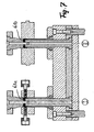
- Fig. 1 shows a functional diagram of an axial section through a shock absorber which connects two relatively movable parts, such as a vehicle axle and a vehicle frame together.
- the shock absorber has a cylinder part 1, which is connected to one of the two relatively movable parts.
- a piston 2 is guided, which is fixed to a piston rod 3, which is fixed with its free end on the other part of the two relatively movable parts.
- the cylinder 1 is in this case closed on both sides and filled with a hydraulic fluid, so that the piston-cylinder arrangement is designed double-acting, wherein the piston two cylinder chambers 4, 5 separates from each other.
- the piston body 6 of the piston 2 has a plurality of adjacent passageways 7, 8.
- the passageways 7, 8 are each covered on their in the function yet to be explained outlet side with a throttle valve 7.1 or 8.1.
- the arrangement is in this case made such that in each case a plurality of passage channels 7 and a plurality of passage channels 8 are provided alternately arranged around the cylinder axis.
- the peripheral surface of the piston 2 is provided with a sleeve-shaped seal 9, which ensures a seal of the cylinder chamber 4 with respect to the cylinder chamber 5.
- the passage openings 8 are in this case kept closed by the pressure on the throttle valves 8.1 fluid space 4.
- the passage channels 7 are closed by the throttle valves 7.1, while the liquid can flow back through the channels 8 flowing through from the cylinder chamber 5 into the cylinder chamber 4.
- the blank 6.1 is provided on its peripheral surface with a plurality of longitudinal support webs 10, each defining respective groove-shaped recesses 11 and which is assigned from the end face 4.1, which is a circulating bar 12, to the other end of the blank 6.1 in the area near the Extend face 5.1.
- the circumferential web 12 and the longitudinal support webs 10, which form an outer surface of the piston body 6, are at the same level. For better illustration, this outer surface is hatched.
- the support webs 10 and correspondingly the grooves 11 are axially parallel.
- Fig. 3 is the piston body 6 in accordance with a horizontal section. the line III-III in Fig. 2 represented, so that the structure of support webs 10 and grooves 11 can be seen.
- Fig. 4 the piston body 6 is shown partially in section and in side view without seal 9 in its final form after the introduction of transverse grooves 11.1 on the surface of the longitudinal webs 10.
- the transverse grooves 11.1 are introduced by an embossing process, as will be explained below, in the sintered blank 6.1, which is then still calibrated after the embossing process.
- the seal 9 is then applied.
- the arranged on the circumference of the piston body 6 cuff-shaped seal 9 is made of a thermoformable plastic, preferably made of PTFE.
- the sleeve-shaped seal 9 has been formed in the embodiment shown here by hot working on the piston body 6.
- the support webs 10 and the circulating web 12 are formed only over part of their height in the material of the sleeve-shaped seal 9, so that between the material of the seal 9 and the bottom groove-shaped recesses 11 still a certain amount of free space remains, so that the sealing material 9 can flow freely and without forcing into the groove 11 during the molding of the seal.
- the cylindrical outer surface 13 of the seal 9 is calibrated simultaneously, so that the desired tolerances to the inner diameter of the cylinder 1 can be maintained.
- Fig. 5 is the positioning of the seal 9 in greatly enlarged scale in a partial section accordingly Fig. 4 shown.
- the seal 9 in this case consists of a homogeneous material, which in the above-described hot forming Partially formed in the longitudinal grooves 11 and the transverse grooves 11.1, while on the other hand, the longitudinal support webs 10 and the circumferential web 12 form correspondingly in the material.
- the material formed in the longitudinal groove 11 is provided with cross-hatching to make it clear that the longitudinal grooves 11 are not completely filled.
- the longitudinal groove 11 in this area in the direction of the circumferential land 12 a decreasing, d. H. having reduced depth.
- the thus caused reduction of the axial support surface for the sealing material on the circumferential web 12 is compensated by the additional axially acting support surfaces of the transverse grooves 11.1 and obtained the advantage that in this highly stressed area in later operation, the material is subjected to less stress by the hot deformation in its structure and thus has a higher stability.
- Fig. 6 . 7 and 8th is the inventive method for producing a piston body of in Fig. 4 illustrated form explained in more detail.
- a green compact accordingly Fig.2 pressed and then sintered to a blank 6.1 finished, as in Fig. 6 represented, each taken from a stock S1 of blanks 6.1 a blank 6.1a and fed to a pressing device P, which has a first press point I and a second press point II.
- the first press point I is provided in addition to the usual upper punch 15.1 and lower punch 16 with radially guided embossing tools 14, via which, as will be explained in more detail below, the transverse grooves 11.1 are introduced into the support webs 10.
- the blank 6.1b provided with transverse grooves in the pressing step I in the preceding embossing step is then fed to the second pressing point II in which the thus prepared blank 6.1b is corresponding both with respect to the piston end surfaces and with respect to the outer circumference of the circulating web and the support webs is calibrated to a finished piston body 6.
- This process is in Fig. 7 shown.
- the movable upper punch 15.2 is assigned a lower punch 16.2, the mold surface of the mold surface of the blank to be inserted 6.1a and 6.1b corresponds.
- the first nip I is held by the movable punch 15.1 and by the fixed counter punch 16.1 of the blank 6.1a practically only while in the second nip II of the ram 15.2 is pressurized in such a manner that a calibrating final deformation of the inserted blank 6.1 b takes place to form the finished piston body 6.
- the ram 15 are withdrawn and ejected via a discharge tool 17 at both pressing points of the now provided with transverse grooves blank 6.1b and the finished calibrated piston body 6 from the mold, so that the blank 6.1b can be transported to the nip II and the finished Piston body 6 can be stored in a bearing S2, from which then the finished piston body for the application of the sleeve-shaped seal 9 are removed.
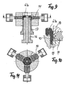
- Fig. 9 is shown in a vertical section through the first press point I, the arrangement with inserted blank 6.1a.
- the retracted upper punch 15.1 is not shown here.
- the embossing tools 14 are pressed into the material of the support webs 10 and the transverse grooves 11.1 formed. This is the enlarged view in Fig. 10 refer to.
- the radially deliverable embossing tools 14 are formed slider-like and, as from the Figure 6 . 7 . 10 and 11 visible, radially deliverable against the blank 6.1a.
- three embossing tools 14 are provided, which are arranged at the same angular distance from each other. Depending on the size, the arrangement of more than three embossing tools can be provided. The arrangement of only two diametrically opposed embossing tools is in principle possible.
- each stamping tool 14 for the formation of two transverse grooves 11.1 in the support webs 10 of a blank 6.1 two parallel cutting edge-like embossing edges 18, by the pressurization of the stamping tools 14 under cold deformation of the sintered material accordingly Fig. 7 Material is displaced and the transverse grooves 11.1 are formed.
- this cold forming takes place only over part of the total height of the support ribs 10, so that the transverse grooves 11.1 arise, which have a smaller depth than the grooves 11th
- the molding and calibration process can also be carried out with only one press point, which essentially corresponds to the pressing point I in construction. Only the upper punch and the lower punch are formed according to the upper punch 15.2 and the lower punch 16.2. Accordingly, in the first step, the blank 6.1a is only fixed by the upper punch and lower punch, so that the transverse grooves 11.1 can be formed. Subsequently, the embossing tools 14 are withdrawn and the pressure on the upper punch and lower punch is increased and the blank is calibrated and only then removed from the mold as a finished piston body.
Landscapes
- Engineering & Computer Science (AREA)
- General Engineering & Computer Science (AREA)
- Mechanical Engineering (AREA)
- Chemical & Material Sciences (AREA)
- Combustion & Propulsion (AREA)
- Pistons, Piston Rings, And Cylinders (AREA)
- Fluid-Damping Devices (AREA)
- Powder Metallurgy (AREA)
- Forging (AREA)
Abstract
Description
Aus
Aus
Aus
Aus
Die beiden vorstehend beschriebenen Verfahren weisen den Nachteil auf, daß für das Umformen und das vollständige Einpressen des Dichtungsmaterials in die Rillen auf der Umfangsfläche des Kolbenkörpers erhebliche Preßdrücke erforderlich sein können und das die Dichtung bildende Dichtungsmaterial starken Umformungen unterworfen wird, die nachteilig die Struktur des Dichtungswerkstoffs beeinflußt.The two methods described above have the disadvantage that for the forming and the complete pressing of the sealing material in the grooves on the peripheral surface of the piston body, considerable pressing pressures may be required and the seal material forming the seal material is subjected to strong transformations, which adversely affects the structure of the sealing material affected.
Aus
Diese vorbekannte Lösung hat gezeigt, daß es für eine gute Abdichtung zwischen der manschettenförmigen Dichtung des Kolbens einerseits und der Außenkontur des Kolbenkörpers andererseits nicht erforderlich ist, daß die Dichtung auf dem vollen Umfang dicht am Kolbenkörper anliegt. Es genügt für eine Reihe von Einsatzfällen, wenn die Dichtmanschette in Umfangsrichtung nur auf dem relativ schmalen Umlaufsteg fest anliegt. Es hat sich ferner überraschenderweise herausgestellt, daß es für eine einwandfreie und zuverlässige Verbindung zwischen Dichtung und Kolbenkörper nicht erforderlich ist, daß die nutförmigen Ausnehmungen zwischen den längslaufenden Stützstegen vom Dichtungsmaterial vollständig ausgefüllt sind. Somit verbleibt ein genügender Freiraum, in den das Dichtungsmaterial bei Ausdehnungen infolge Temperaturerhöhungen ausweichen kann, wobei der Kolben jedoch über die längslaufenden Stützstege einwandfrei geführt ist.This prior art solution has shown that it is not necessary for a good seal between the sleeve-shaped seal of the piston on the one hand and the outer contour of the piston body on the other hand, that the seal rests on the full circumference close to the piston body. It is sufficient for a number of applications, when the sealing sleeve in the circumferential direction only firmly rests on the relatively narrow circumferential web. It has also surprisingly been found that it is not necessary for a perfect and reliable connection between the seal and the piston body, that the groove-shaped recesses between the longitudinal support webs are completely filled by the sealing material. Thus, there remains a sufficient clearance into which the sealing material can escape during expansion due to temperature increases, but the piston is properly guided over the longitudinal support webs.
Die Anordnung nur eines, die Umfangsfläche überragenden Umlaufstegs zur Fixierung der manschettenförmigen Dichtung kann unter Umständen nicht ausreichen, so daß die Anordnung von zwei jeweils endseitigen Umlaufstegen wünschenswert ist, die durch die längslaufenden, mit Abstand parallel zueinander angeordneten Stützstege verbunden sind. Die pulvermetallurgische Herstellung eines derartigen Kolbenkörpers durch Pressen eines Grünlings aus einem sinterbaren Metallpulver mit anschließendem Sintern bereitet jedoch erhebliche formungstechnische Probleme, so daß in die
Der Erfindung liegt die Aufgabe zugrunde, einen einfacher herzustellenden Kolben, insbesondere Stoßdämpferkolben zu schaffen.The invention has for its object to provide a simpler to manufacture pistons, in particular shock absorber piston.
Diese Aufgabe wird gemäß der Erfindung durch einen einteiligen Kolbenkörper mit den Merkmalen des Anspruchs 1 gelöst.This object is achieved according to the invention by a one-piece piston body having the features of
Ein Verfahren zur Herstellung des erfindungsgemäßen Kolbenkörpers ist im Anspruch 6 angegeben.A method for producing the piston body according to the invention is specified in
Weitere Ausgestaltungen der Erfindung sind in der nachfolgenden Beschreibung von Ausführungsbeispielen und den Unteransprüchen angegeben.Further embodiments of the invention are specified in the following description of exemplary embodiments and the subclaims.
Die Erfindung wird anhand schematischer Zeichnungen eines Ausführungsbeispiels näher erläutert. Es zeigen:
- Fig. 1
- einen Teilschnitt in Achsrichtung durch eine Kolben-Zylinder-Anordnung für einen Stoßdämpfer,
- Fig. 2
- eine Seitenansicht, teilweise im Schnitt, eines fertig gesinterten Rohligs für einen Stoßdämpfer,
- Fig. 3
- einen schematischen Horizontalschnitt durch den Rohling gemäß der Linie III-III in
Fig. 2 ohne Dichtmanschette, - Fig. 4
- eine Seitenansicht eines fertig geformten Kolbenkörpers, teilweise im Schnitt, mit aufgebrachter Dichtmanschette,
- Fig. 5
- einen Teilschnitt gem.
Fig. 4 in vergrößerter Darstellung, - Fig. 6
- eine Vorrichtung zum Formen von Quernuten und Kalibrieren eines Kolbenkörperrohlings als Schritt des Herstellungsverfahrens,
- Fig. 7
- die Vorrichtung gemäß
Fig. 6 während des Formungs- und Kalibrierschrittes, - Fig. 8
- die Vorrichtung gem.
Fig. 6 am Ende des Formungs- und Kalibrierschrittes, - Fig. 9
- einen Vertikalschnitt durch die Formungsstation des Werkzeuges gem.
Fig. 6 mit eingelegtem Rohling beim Formungsprozeß, - Fig. 10
- in vergrößerter Darstellung die Ausbildung des Prägewerkzeuges,
- Fig. 11
- eine Aufsicht auf die Formungsstation gem.
Fig. 9 mit einer Anordnung der Prägewerkzeuge.
- Fig. 1
- a partial section in the axial direction by a piston-cylinder assembly for a shock absorber,
- Fig. 2
- a side view, partly in section, of a finished sintered brute for a shock absorber,
- Fig. 3
- a schematic horizontal section through the blank according to the line III-III in
Fig. 2 without sealing collar, - Fig. 4
- a side view of a finished shaped piston body, partially in section, with applied sealing sleeve,
- Fig. 5
- a partial section acc.
Fig. 4 in an enlarged view, - Fig. 6
- a device for forming transverse grooves and calibrating a piston body blank as a step of the manufacturing method,
- Fig. 7
- the device according to
Fig. 6 during the molding and calibration step, - Fig. 8
- the device acc.
Fig. 6 at the end of the molding and calibration step, - Fig. 9
- a vertical section through the molding station of the tool acc.
Fig. 6 with inserted blank during the molding process, - Fig. 10
- in an enlarged view the formation of the embossing tool,
- Fig. 11
- a view of the molding station gem.
Fig. 9 with an arrangement of embossing tools.
Der Kolbenkörper 6 des Kolbens 2 weist mehrere nebeneinander verlaufende Durchtrittskanäle 7, 8 auf. Die Durchtrittskanäle 7, 8 sind jeweils auf ihrer in der Funktion noch zu erläuternden Austrittsseite mit einem Drosselventil 7.1 bzw. 8.1 abgedeckt. Die Anordnung ist hierbei so getroffen, daß jeweils mehrere Durchtrittskanäle 7 und mehrere Durchtrittskanäle 8 alternierend um die Zylinderachse angeordnet vorgesehen sind.The
Die Umfangsfläche des Kolbens 2 ist mit einer manschettenförmigen Dichtung 9 versehen, die für eine Abdichtung des Zylinderraums 4 gegenüber dem Zylinderraum 5 sorgt. Bei einer Bewegung des Kolbens 2 in den Zylinderraum 4 hinein, wird die Flüssigkeit durch die Durchtrittskanäle 7 gegen die Rückstellkraft der Drosselventile 7.1 gepreßt. Die Durchtrittsöffnungen 8 werden hierbei durch den auf die Drosselventile 8.1 lastenden Druck des Flüssigkeitsraums 4 verschlossen gehalten. Bei einer Bewegung in umgekehrter Richtung werden die Durchtrittskanäle 7 durch die Drosselventile 7.1 geschlossen, während die Flüssigkeit durch die durchströmenden Kanäle 8 aus dem Zylinderraum 5 in den Zylinderraum 4 zurückströmen kann.The peripheral surface of the
Da nun ein derartiger Kolbenkörper, wie vorstehend angegeben, hin und her bewegt wird und bei hohen Beanspruchungen die manschettenförmige Dichtung 9 auch bei der Rückbewegung entsprechend belastet wird, reicht ein endseitiger Umlaufsteg an einem Ende des Kolbenkörpers für eine sichere Fixierung der manschettenförmigen Dichtung gegenüber Belastung in axialer Richtung unter Umständen nicht mehr aus. Um nun einen derartigen Kolbenkörper in einteiliger Form so herstellen zu können, daß zusätzliche Quernuten zur Fixierung der manschettenförmigen Dichtung vorhanden sind, wird zunächst aus sinterbarem Metallpulver ein Grünling in der in
Der Rohling 6.1 ist auf seiner Umfangsfläche mit einer Vielzahl von längslaufenden Stützstegen 10 versehen, die jeweils entsprechende nutförmige Ausnehmungen 11 begrenzen und die sich von der Stirnfläche 4.1, der ein Umlaufsteg 12 zugeordnet ist, bis an das andere Ende des Rohlings 6.1 im Bereich nahe der Stirnfläche 5.1 erstrecken. Der Umlaufsteg 12 und die längslaufenden Stützstege 10, die eine Außenfläche des Kolbenkörpers 6 bilden, sind niveaugleich. Aus Gründen einer besseren Darstellung ist diese Außenfläche mit einer Schraffur versehen. Die Stützstege 10 und entsprechend die Nuten 11 verlaufen achsparallel.The blank 6.1 is provided on its peripheral surface with a plurality of
In
In
Die auf dem Umfang des Kolbenkörpers 6 angeordnete manschettenförmige Dichtung 9 besteht aus einem warmverformbaren Kunststoff, vorzugsweise aus PTFE. Die manschettenförmige Dichtung 9 ist bei dem hier dargestellten Ausführungsbeispiel durch Warmumformung auf den Kolbenkörper 6 aufgeformt worden.The arranged on the circumference of the
Bei der Warmumformung des Dichtungsmaterials, das aus einer vorkonfektionierten Kreisringscheibe oder einem vorkonfektionierten Rohrstück bestehen kann, werden die Stützstege 10 und der Umlaufsteg 12 nur über einen Teil ihrer Höhe in das Material der manschettenförmigen Dichtung 9 eingeformt, so daß zwischen dem Material der Dichtung 9 und dem Boden nutförmigen Ausnehmungen 11 noch ein gewisser Freiraum verbleibt, so daß beim Formen der Dichtung 9 das Dichtungsmaterial frei und ohne Zwängung in die Nut 11 einfließen kann. Bei diesem Umformungsvorgang wird die zylindrische Außenfläche 13 der Dichtung 9 gleichzeitig kalibriert, so daß die gewünschten Toleranzen zum Innendurchmesser des Zylinders 1 eingehalten werden können. Da insbesondere bei der Verwendung einer derartigen Kolben-Zylinder-Anordnung als Stoßdämpfer im Betrieb eine Erwärmung des Gesamtsystems auftritt, erlaubt dieser verbleibende Freiraum im Nutgrund innerhalb gewisser Grenzen auch eine Ausdehnung des Dichtungsmaterials in die Nut hinein, so daß der Verschleiß der Dichtung auf der an die Ränder angrenzenden zylindrischen Umfangsfläche der Dichtung 9 herabgesetzt wird. Der Kolben 2 ist über seine Höhe insgesamt praktisch kippfrei abgestützt. Die Dichtung 9 stützt sich an dem einen Nutenenden auf der Innenseite des Umlaufstegs 12 ab.In the hot forming of the sealing material, which may consist of a prefabricated circular ring disk or a pre-assembled pipe section, the
In
Um bei der Warmumformung das Material der Dichtung 9 in der längslaufenden Nut 11 im Übergangsbereich B zum Umlaufsteg 12 nicht überbeanspruchen, ist hierbei vorgesehen, daß die längslaufende Nut 11 in diesem Bereich in Richtung auf den Umlaufsteg 12 eine abnehmende, d. h. reduzierte Tiefe aufweist. Die so bewirkte Reduzierung der axialen Stützfläche für das Dichtungsmaterial am Umlaufsteg 12 wird durch die zusätzlichen, in Axialrichtung wirkenden Stützflächen der Quernuten 11.1 kompensiert und der Vorteil gewonnen, daß in diesem im späteren Betrieb hochbeanspruchten Bereich das Material durch die Warmumformung in seinem Gefüge geringer beansprucht ist und somit eine höhere Standfestigkeit aufweist.In order not to overstress during the hot forming the material of the
Anhand der
Die erste Preßstelle I ist neben dem üblichen Oberstempel 15.1 und Unterstempel 16 mit radial geführten Prägewerkzeugen 14 versehen, über die, wie nachstehend noch näher erläutert werden wird, die Quernuten 11.1 in die Stützstege 10 eingebracht werden.The first press point I is provided in addition to the usual upper punch 15.1 and
Der im voraufgegangenen Prägeschritt in der Preßstelle I mit Quernuten versehene Rohling 6.1b wird dann der zweiten Preßstelle II zugeführt, in der der so vorbereitete Rohling 6.1b sowohl in bezug auf die Kolbenendflächen als auch in bezug auf den äußeren Umfang des Umlaufsteges und der Stützstege entsprechend zu einem fertigen Kolbenkörper 6 kalibriert wird. Dieser Vorgang ist in
In der Preßstelle II ist dem beweglichen Oberstempel 15.2 ist ein Unterstempel 16.2 zugeordnet, dessen Formoberfläche der Formoberfläche des einzulegenden Rohlings 6.1a bzw. 6.1b entspricht. In der ersten Preßstelle I wird durch den bewegbaren Stempel 15.1 und durch den feststehenden Gegenstempel 16.1 der Rohling 6.1a praktisch nur gehalten, während in der zweiten Preßstelle II der Preßstempel 15.2 in der Weise mit Druck beaufschlagt wird, daß eine kalibrierende Endverformung des eingelegten Rohlings 6.1b zur Bildung des fertigen Kolbenkörpers 6 stattfindet.In the pressing point II the movable upper punch 15.2 is assigned a lower punch 16.2, the mold surface of the mold surface of the blank to be inserted 6.1a and 6.1b corresponds. In the first nip I is held by the movable punch 15.1 and by the fixed counter punch 16.1 of the blank 6.1a practically only while in the second nip II of the ram 15.2 is pressurized in such a manner that a calibrating final deformation of the inserted blank 6.1 b takes place to form the
Wie in
In
Die radial zustellbaren Prägewerkzeuge 14 sind schieberartig ausgebildet und, wie aus den
Wie aus der vergrößerten Darstellung gem.
Der Form- und Kalibriervorgang kann auch mit nur einer Preßstelle ausgeführt werden, die im Aufbau im wesentlichen der Preßstelle I entspricht. Lediglich der Oberstempel und der Unterstempel sind entsprechend dem Oberstempel 15.2 und dem Unterstempel 16.2 ausgebildet. Dementsprechend wird im ersten Schritt der Rohling 6.1a vom Oberstempel und Unterstempel nur fixiert, so daß die Quernuten 11.1 eingeformt werden können. Anschließend werden die Prägewerkzeuge 14 zurückgezogen und der Druck auf Oberstempel und Unterstempel erhöht und der Rohling kalibriert und erst dann der Form als fertiger Kolbenkörper entnommen.The molding and calibration process can also be carried out with only one press point, which essentially corresponds to the pressing point I in construction. Only the upper punch and the lower punch are formed according to the upper punch 15.2 and the lower punch 16.2. Accordingly, in the first step, the blank 6.1a is only fixed by the upper punch and lower punch, so that the transverse grooves 11.1 can be formed. Subsequently, the
Claims (9)
- A piston body produced by powder metallurgy for a piston / cylinder arrangement, in particular a shock-absorber piston, having a one-part piston body (6) which is provided on its peripheral face in an area adjacent to a piston-end face (4.1) with a circulating continuous web (12) which projects beyond the peripheral face and which is adjoined by longitudinally extending support webs (10) which extend to the other piston-end face (5.1) and which are arranged parallel to and adjacent to one another at a distance, wherein two adjacent support webs (10) bound a groove-shaped recess (11) in each case, wherein a collar-shaped seal (9) made of a thermally deformable sealing material is capable of being formed on the piston body (6) in such a way that both the continuous web (12) and the support webs (10) are formed in the material of the collar-shaped seal (9) at least over a part of their height, characterized in that at least part of the longitudinally extending support webs (10) between the two piston-end faces (4.1, 5.1) is provided with at least one transverse groove (11.1), wherein the groove-shaped recesses (11) are open in the longitudinal direction at their end facing away from the continuous web (12).
- A piston body according to Claim 1, characterized in that the depth of the groove-shaped recesses (11) is less in an area (B) adjacent to the continuous web (12) than in the area of the end face (5.1) facing away from the continuous web (12).
- A piston body according to Claim 1 or 2, characterized in that at least two transverse grooves (11.1) are provided.
- A piston body according to any one of Claims 1 to 3, characterized in that the transverse groove (11.1) has a depth less than that of the groove-shaped recess (11).
- A piston body according to any one of Claims 1 to 4, characterized in that a collar-shaped seal (9) made of a thermally deformable plastics material, preferably PTFE, is formed on the piston body by means of thermal deformation, wherein the seal (9) does not completely fill the groove-shaped recess (11) and does completely fill the transverse grooves (11.1).
- A method of producing a one-part piston body for a piston / cylinder arrangement, in particular a shock-absorber piston, which is provided on its peripheral face in an area adjacent to a piston-end face (4.1) with a circulating continuous web (12) which projects beyond the peripheral face and which is adjoined by longitudinally extending support webs (10) which extend to the other piston-end face (5.1) and which are arranged parallel to and at a distance from one another, wherein two adjacent support webs (10) bound a groove-shaped recess (11) in each case and are open in the longitudinal direction at their ends facing away from the continuous web, characterized in that in a first step a green compact comprising the continuous web and the longitudinally extending support webs is pressed from a metallurgical powder capable of being sintered, in a second step the green compact is finally sintered to form a blank (6.1), in a third step stamping tools (14) guided radially are used to form, under material displacement, transverse grooves (111.1) in at least a part of the support webs (10) by cold deformation, and in a fourth step the blank (6.1) provided with transverse grooves (11.1) in this way is calibrated to its final form by pressing with calibrating tools.
- A method according to Claim 6, characterized in that use is made of at least two stamping tools (14) which are capable of being pressed radially against the blank and which [have] at least one blade-type stamping edge in each case.
- A method according to Claim 6 or 7, characterized in that a pressing device (P) with at least two press locations (I, II) is used, wherein a blank (6.1a) is provided with transverse grooves (11.1) in the first press location (I), whilst a blank (6.1b) provided with the transverse grooves (11.1) is simultaneously calibrated in the second press location (II).
- A method according to any one of Claims 6 to 8, characterized in that in the third step for producing the transverse grooves (11.1) the blank (6. lea) is in practice only held by a movable upper stamp (15.1) and a stationary lower stamp (16.1), whilst the transverse grooves (11.1) are formed in the support webs (10) by the radially guided stamping tool (14) over a depth of less than the depth of the groove-shaped recess (11).
Applications Claiming Priority (3)
| Application Number | Priority Date | Filing Date | Title |
|---|---|---|---|
| DE10245404 | 2002-09-28 | ||
| DE10245404A DE10245404A1 (en) | 2002-09-28 | 2002-09-28 | Piston body for piston-cylinder-units, esp. shock absorber piston has sintered powder-metallurgic body with integrated projecting and support webs |
| PCT/EP2003/009670 WO2004033931A1 (en) | 2002-09-28 | 2003-08-30 | Powder-metallurgically produced piston body comprising support webs and method for the production thereof |
Publications (3)
| Publication Number | Publication Date |
|---|---|
| EP1543254A1 EP1543254A1 (en) | 2005-06-22 |
| EP1543254B1 true EP1543254B1 (en) | 2008-10-15 |
| EP1543254B8 EP1543254B8 (en) | 2009-01-07 |
Family
ID=31984220
Family Applications (1)
| Application Number | Title | Priority Date | Filing Date |
|---|---|---|---|
| EP03807820A Expired - Lifetime EP1543254B8 (en) | 2002-09-28 | 2003-08-30 | Powder-metallurgically produced piston body comprising support webs and method for the production thereof |
Country Status (11)
| Country | Link |
|---|---|
| US (2) | US7310876B2 (en) |
| EP (1) | EP1543254B8 (en) |
| JP (1) | JP4347217B2 (en) |
| KR (1) | KR100675528B1 (en) |
| CN (1) | CN100362258C (en) |
| AT (1) | ATE411483T1 (en) |
| AU (1) | AU2003255499A1 (en) |
| BR (1) | BR0314786A (en) |
| DE (2) | DE10245404A1 (en) |
| MX (1) | MXPA05003239A (en) |
| WO (1) | WO2004033931A1 (en) |
Families Citing this family (22)
| Publication number | Priority date | Publication date | Assignee | Title |
|---|---|---|---|---|
| DE102005004956A1 (en) * | 2005-02-02 | 2006-08-17 | Gkn Sinter Metals Holding Gmbh | Bypass-optimized shock absorber piston |
| US7641029B2 (en) * | 2005-12-15 | 2010-01-05 | Ride Control, Llc | Annular groove monotube piston with non-symmetrical band |
| JP4796439B2 (en) * | 2006-05-17 | 2011-10-19 | 株式会社ショーワ | Resin-coated piston device for shock absorbers |
| DE102006029380B3 (en) | 2006-06-27 | 2008-01-17 | Thyssenkrupp Bilstein Suspension Gmbh | damping element |
| KR100720172B1 (en) * | 2006-08-31 | 2007-05-23 | 씨멘스브이디오한라 주식회사 | Switch knob structure of rotary push button switch |
| US8069964B2 (en) * | 2007-06-21 | 2011-12-06 | Tenneco Automotive Operating Company Inc. | Junction bleed |
| DE102009010371A1 (en) * | 2009-02-26 | 2010-09-02 | PMG Füssen GmbH | Powder metallurgical body and process for its preparation |
| DE102010028841B4 (en) * | 2010-05-11 | 2012-01-26 | Zf Friedrichshafen Ag | Dämpfventileinrichtung with a multi-stage Dämpfkraftkennlinie |
| DE102010024126A1 (en) * | 2010-06-17 | 2011-12-22 | Carl Freudenberg Kg | piston accumulators |
| CN104319195B (en) * | 2014-06-27 | 2017-04-05 | 国家电网公司 | Oil bumper and the breaker operation mechanism using the oil bumper |
| US10041560B2 (en) | 2015-02-25 | 2018-08-07 | Michael A Ankney | Piston head assembly for radio controlled cars shock absorber and method |
| US9682605B2 (en) | 2015-02-25 | 2017-06-20 | Michael A Ankney | Variable dampening speed piston head assembly for radio controlled cars shock absorber and method |
| US10174802B2 (en) | 2016-05-11 | 2019-01-08 | Beijingwest Industries Co., Ltd. | Hydraulic damper with a hydraulic stop arrangement |
| DE102016217117A1 (en) * | 2016-09-08 | 2016-12-01 | Zf Friedrichshafen Ag | Frequency-selective damping valve arrangement |
| US10239376B2 (en) | 2016-09-22 | 2019-03-26 | Beijingwest Industries Co., Ltd. | Hydraulic damper with an x-flow piston assembly |
| MX2020001580A (en) | 2017-08-09 | 2020-08-31 | Mainspring Energy Inc | Piston sealing ring assembly having a gap cover element. |
| US10436322B2 (en) | 2017-08-09 | 2019-10-08 | Etagen, Inc. | Piston sealing ring assemblies |
| CA3072557A1 (en) * | 2017-08-09 | 2019-02-14 | Mainspring Energy, Inc. | Sealing ring assemblies configured for pressure locking |
| CN107269755A (en) * | 2017-08-11 | 2017-10-20 | 浙江淅川减振器有限公司 | It is a kind of that there is the big damper for damping diclinic hole piston valve system |
| DE102018106983B4 (en) * | 2018-03-23 | 2022-07-07 | Federal-Mogul Burscheid Gmbh | Piston ring for two-stroke engines with a wear indicator |
| KR102034118B1 (en) * | 2018-04-16 | 2019-10-18 | 한라스택폴 주식회사 | Apparatus for manufacturing banded piston of shock-absorber in vehicle and Method thereof |
| DE102023205446A1 (en) | 2023-06-13 | 2024-12-19 | Zf Friedrichshafen Ag | Adjustable damping valve device |
Family Cites Families (16)
| Publication number | Priority date | Publication date | Assignee | Title |
|---|---|---|---|---|
| US3212411A (en) * | 1964-02-14 | 1965-10-19 | Duriron Co | Fluid tight self-lubricating cylinder assembly |
| DE3004209C2 (en) * | 1980-02-06 | 1983-02-03 | Sintermetallwerk Krebsöge GmbH, 5608 Radevormwald | Process for compacting powders and metals and their alloys into pre-pressed bodies |
| GB8501526D0 (en) * | 1985-01-22 | 1985-02-20 | Ici Plc | Catalyst |
| JP3722495B2 (en) * | 1993-04-30 | 2005-11-30 | 大豊工業株式会社 | Shock absorber piston |
| US5435233A (en) | 1993-07-06 | 1995-07-25 | Tri Dayton, Inc. | Banded piston |
| DE4343428A1 (en) * | 1993-12-18 | 1995-06-22 | Ringsdorff Sinter Gmbh | Injection molded guide and sealing elements on sintered parts for shock absorbers |
| US5611260A (en) * | 1994-07-07 | 1997-03-18 | Unisia Jecs Corporation | Piston ring mount structure |
| DE19847341A1 (en) * | 1998-10-14 | 2000-04-20 | Gkn Sinter Metals Holding Gmbh | Shock absorber piston has circumferential annular projections which carry a thermoplastic sealing collar |
| DE19847343A1 (en) * | 1998-10-14 | 2000-04-20 | Gkn Sinter Metals Holding Gmbh | Piston for shock absorber comprises sealing element over circumferential protrusions, and radial opening connecting circumferential piston groove with at least one axial channel in piston body |
| DE19847342A1 (en) * | 1998-10-14 | 2000-08-17 | Gkn Sinter Metals Holding Gmbh | Pistons with support webs for a piston-cylinder arrangement, in particular shock absorber pistons |
| ES2199601T3 (en) * | 1998-12-04 | 2004-02-16 | W.S. Shamban Europa A/S | PISTON OR EMBOLO AND PROCEDURE TO PREPARE THE SAME. |
| US6305266B1 (en) * | 1998-12-04 | 2001-10-23 | W.S. Shamban Europa A/S | Piston or plunger and a method for making the same |
| DE69921501T2 (en) * | 1998-12-04 | 2006-02-02 | Trelleborg Sealing Solutions Denmark A/S | PISTON AND METHOD FOR ITS MANUFACTURE |
| DE10039764A1 (en) * | 2000-08-16 | 2002-02-28 | Volkswagen Ag | Piston for a shock absorber comprises a gliding foil seal tensioned by ribs which are located on the circumference of the sintered piston body and are joined to one another by intervening bridge pieces |
| DE10108246A1 (en) * | 2001-02-21 | 2002-09-19 | Gkn Sinter Metals Gmbh | Pistons with support webs for a piston-cylinder arrangement, in particular shock absorber pistons |
| EP1371740B1 (en) * | 2001-03-23 | 2008-10-22 | Sumitomo Electric Sintered Alloy, Ltd. | Heat-resistant and creep-resistant aluminum alloy and billet thereof, and method for their production |
-
2002
- 2002-09-28 DE DE10245404A patent/DE10245404A1/en not_active Ceased
-
2003
- 2003-08-30 JP JP2004542339A patent/JP4347217B2/en not_active Expired - Fee Related
- 2003-08-30 EP EP03807820A patent/EP1543254B8/en not_active Expired - Lifetime
- 2003-08-30 WO PCT/EP2003/009670 patent/WO2004033931A1/en active Application Filing
- 2003-08-30 KR KR1020057005347A patent/KR100675528B1/en not_active IP Right Cessation
- 2003-08-30 MX MXPA05003239A patent/MXPA05003239A/en active IP Right Grant
- 2003-08-30 AT AT03807820T patent/ATE411483T1/en not_active IP Right Cessation
- 2003-08-30 AU AU2003255499A patent/AU2003255499A1/en not_active Abandoned
- 2003-08-30 DE DE50310656T patent/DE50310656D1/en not_active Expired - Lifetime
- 2003-08-30 CN CNB038228300A patent/CN100362258C/en not_active Expired - Fee Related
- 2003-08-30 BR BR0314786-0A patent/BR0314786A/en not_active IP Right Cessation
-
2005
- 2005-03-28 US US11/091,246 patent/US7310876B2/en not_active Expired - Fee Related
-
2007
- 2007-11-27 US US11/945,876 patent/US20080289491A1/en not_active Abandoned
Also Published As
| Publication number | Publication date |
|---|---|
| ATE411483T1 (en) | 2008-10-15 |
| EP1543254B8 (en) | 2009-01-07 |
| KR100675528B1 (en) | 2007-01-30 |
| BR0314786A (en) | 2005-07-26 |
| US20050167220A1 (en) | 2005-08-04 |
| WO2004033931A1 (en) | 2004-04-22 |
| US7310876B2 (en) | 2007-12-25 |
| CN100362258C (en) | 2008-01-16 |
| DE50310656D1 (en) | 2008-11-27 |
| EP1543254A1 (en) | 2005-06-22 |
| US20080289491A1 (en) | 2008-11-27 |
| CN1695016A (en) | 2005-11-09 |
| DE10245404A1 (en) | 2004-04-08 |
| JP2006500541A (en) | 2006-01-05 |
| KR20050057601A (en) | 2005-06-16 |
| AU2003255499A1 (en) | 2004-05-04 |
| JP4347217B2 (en) | 2009-10-21 |
| MXPA05003239A (en) | 2005-07-05 |
Similar Documents
| Publication | Publication Date | Title |
|---|---|---|
| EP1543254B1 (en) | Powder-metallurgically produced piston body comprising support webs and method for the production thereof | |
| EP1121543B1 (en) | Piston with pressure-dependent sealing effect for a piston-cylinder arrangement, especially a shock absorber piston | |
| DE19727180C2 (en) | Hydraulic valve, in particular for controlling a camshaft adjustment in a motor vehicle | |
| EP1121542B1 (en) | Piston with support webs for a piston-cylinder arrangement, especially a shock absorber piston | |
| DE4110023A1 (en) | SHOCK ABSORBER PISTON FROM UNEQUAL, JOINTED PARTS | |
| EP1362197B1 (en) | Piston with supporting connector elements for a piston-cylinder arrangement, especially a shock absorber piston | |
| DE69921501T2 (en) | PISTON AND METHOD FOR ITS MANUFACTURE | |
| EP1121544B1 (en) | Piston for a piston-cylinder arrangement, especially shock absorber piston | |
| DE102012019618B4 (en) | Method for producing a piston for a reciprocating piston working machine, piston produced by the method and reciprocating piston working machine with at least one piston produced by the method | |
| DE69301520T2 (en) | Method for producing a tappet for an internal combustion engine | |
| WO2003093654A1 (en) | Single-piece cam, method for the production thereof, and assembly of a camshaft | |
| EP0505773B1 (en) | Shock absorber piston out of dissimilar, joined pieces | |
| EP1279449B1 (en) | Method for connecting two objects | |
| EP0826450B1 (en) | Process for forming to final size of a recess | |
| EP0682999B1 (en) | Article molded from metal powder and process and apparatus for preparing the same | |
| EP3302948B1 (en) | Closing force unit | |
| WO1999025506A1 (en) | Method and device for producing an integral housing for a hydraulic steering gear | |
| DE10120880B4 (en) | Process for the production of deep drawn parts | |
| DE2622138A1 (en) | METHOD OF MANUFACTURING AN EXTRUDED STEEL PART FOR USE IN A ROLLER CLUTCH | |
| DE2026420A1 (en) | Method for the fixed, in particular sealed connection of a hollow body with an outer part enclosing the hollow body on all sides | |
| DE10343430B3 (en) | Manufacturing process for making tube with thickened wall in central portion has two annular pistons with profiled ends forced toward each other while fluid flows in through holes in outer tube | |
| DE102012106643B3 (en) | Method for manufacturing pressure container in vehicle, involves forming grooves at openings in web wall by stamping of material of web wall without cutting |
Legal Events
| Date | Code | Title | Description |
|---|---|---|---|
| PUAI | Public reference made under article 153(3) epc to a published international application that has entered the european phase |
Free format text: ORIGINAL CODE: 0009012 |
|
| 17P | Request for examination filed |
Effective date: 20050216 |
|
| AK | Designated contracting states |
Kind code of ref document: A1 Designated state(s): AT BE BG CH CY CZ DE DK EE ES FI FR GB GR HU IE IT LI LU MC NL PT RO SE SI SK TR |
|
| AX | Request for extension of the european patent |
Extension state: AL LT LV MK |
|
| DAX | Request for extension of the european patent (deleted) | ||
| 17Q | First examination report despatched |
Effective date: 20070305 |
|
| GRAP | Despatch of communication of intention to grant a patent |
Free format text: ORIGINAL CODE: EPIDOSNIGR1 |
|
| GRAS | Grant fee paid |
Free format text: ORIGINAL CODE: EPIDOSNIGR3 |
|
| GRAA | (expected) grant |
Free format text: ORIGINAL CODE: 0009210 |
|
| AK | Designated contracting states |
Kind code of ref document: B1 Designated state(s): AT BE BG CH CY CZ DE DK EE ES FI FR GB GR HU IE IT LI LU MC NL PT RO SE SI SK TR |
|
| REG | Reference to a national code |
Ref country code: CH Ref legal event code: EP Ref country code: GB Ref legal event code: FG4D Free format text: NOT ENGLISH |
|
| RAP2 | Party data changed (patent owner data changed or rights of a patent transferred) |
Owner name: GKN SINTER METALS HOLDING GMBH |
|
| REG | Reference to a national code |
Ref country code: IE Ref legal event code: FG4D Free format text: LANGUAGE OF EP DOCUMENT: GERMAN |
|
| REF | Corresponds to: |
Ref document number: 50310656 Country of ref document: DE Date of ref document: 20081127 Kind code of ref document: P |
|
| NLT2 | Nl: modifications (of names), taken from the european patent patent bulletin |
Owner name: GKN SINTER METALS HOLDING GMBH Effective date: 20081105 |
|
| NLV1 | Nl: lapsed or annulled due to failure to fulfill the requirements of art. 29p and 29m of the patents act | ||
| PG25 | Lapsed in a contracting state [announced via postgrant information from national office to epo] |
Ref country code: ES Free format text: LAPSE BECAUSE OF FAILURE TO SUBMIT A TRANSLATION OF THE DESCRIPTION OR TO PAY THE FEE WITHIN THE PRESCRIBED TIME-LIMIT Effective date: 20090126 Ref country code: BG Free format text: LAPSE BECAUSE OF FAILURE TO SUBMIT A TRANSLATION OF THE DESCRIPTION OR TO PAY THE FEE WITHIN THE PRESCRIBED TIME-LIMIT Effective date: 20090115 |
|
| REG | Reference to a national code |
Ref country code: HU Ref legal event code: AG4A Ref document number: E004743 Country of ref document: HU |
|
| PG25 | Lapsed in a contracting state [announced via postgrant information from national office to epo] |
Ref country code: NL Free format text: LAPSE BECAUSE OF FAILURE TO SUBMIT A TRANSLATION OF THE DESCRIPTION OR TO PAY THE FEE WITHIN THE PRESCRIBED TIME-LIMIT Effective date: 20081015 Ref country code: FI Free format text: LAPSE BECAUSE OF FAILURE TO SUBMIT A TRANSLATION OF THE DESCRIPTION OR TO PAY THE FEE WITHIN THE PRESCRIBED TIME-LIMIT Effective date: 20081015 Ref country code: SI Free format text: LAPSE BECAUSE OF FAILURE TO SUBMIT A TRANSLATION OF THE DESCRIPTION OR TO PAY THE FEE WITHIN THE PRESCRIBED TIME-LIMIT Effective date: 20081015 Ref country code: PT Free format text: LAPSE BECAUSE OF FAILURE TO SUBMIT A TRANSLATION OF THE DESCRIPTION OR TO PAY THE FEE WITHIN THE PRESCRIBED TIME-LIMIT Effective date: 20090316 |
|
| REG | Reference to a national code |
Ref country code: IE Ref legal event code: FD4D |
|
| PG25 | Lapsed in a contracting state [announced via postgrant information from national office to epo] |
Ref country code: IE Free format text: LAPSE BECAUSE OF FAILURE TO SUBMIT A TRANSLATION OF THE DESCRIPTION OR TO PAY THE FEE WITHIN THE PRESCRIBED TIME-LIMIT Effective date: 20081015 Ref country code: EE Free format text: LAPSE BECAUSE OF FAILURE TO SUBMIT A TRANSLATION OF THE DESCRIPTION OR TO PAY THE FEE WITHIN THE PRESCRIBED TIME-LIMIT Effective date: 20081015 Ref country code: DK Free format text: LAPSE BECAUSE OF FAILURE TO SUBMIT A TRANSLATION OF THE DESCRIPTION OR TO PAY THE FEE WITHIN THE PRESCRIBED TIME-LIMIT Effective date: 20081015 Ref country code: RO Free format text: LAPSE BECAUSE OF FAILURE TO SUBMIT A TRANSLATION OF THE DESCRIPTION OR TO PAY THE FEE WITHIN THE PRESCRIBED TIME-LIMIT Effective date: 20081015 |
|
| PLBE | No opposition filed within time limit |
Free format text: ORIGINAL CODE: 0009261 |
|
| STAA | Information on the status of an ep patent application or granted ep patent |
Free format text: STATUS: NO OPPOSITION FILED WITHIN TIME LIMIT |
|
| PG25 | Lapsed in a contracting state [announced via postgrant information from national office to epo] |
Ref country code: SE Free format text: LAPSE BECAUSE OF FAILURE TO SUBMIT A TRANSLATION OF THE DESCRIPTION OR TO PAY THE FEE WITHIN THE PRESCRIBED TIME-LIMIT Effective date: 20090115 |
|
| 26N | No opposition filed |
Effective date: 20090716 |
|
| PG25 | Lapsed in a contracting state [announced via postgrant information from national office to epo] |
Ref country code: SK Free format text: LAPSE BECAUSE OF FAILURE TO SUBMIT A TRANSLATION OF THE DESCRIPTION OR TO PAY THE FEE WITHIN THE PRESCRIBED TIME-LIMIT Effective date: 20081015 |
|
| PGFP | Annual fee paid to national office [announced via postgrant information from national office to epo] |
Ref country code: CZ Payment date: 20090820 Year of fee payment: 7 Ref country code: HU Payment date: 20090827 Year of fee payment: 7 |
|
| BERE | Be: lapsed |
Owner name: GKN SINTER METALS G.M.B.H. Effective date: 20090831 |
|
| PG25 | Lapsed in a contracting state [announced via postgrant information from national office to epo] |
Ref country code: MC Free format text: LAPSE BECAUSE OF NON-PAYMENT OF DUE FEES Effective date: 20090831 |
|
| REG | Reference to a national code |
Ref country code: CH Ref legal event code: PL |
|
| PG25 | Lapsed in a contracting state [announced via postgrant information from national office to epo] |
Ref country code: LI Free format text: LAPSE BECAUSE OF NON-PAYMENT OF DUE FEES Effective date: 20090831 Ref country code: CH Free format text: LAPSE BECAUSE OF NON-PAYMENT OF DUE FEES Effective date: 20090831 |
|
| PG25 | Lapsed in a contracting state [announced via postgrant information from national office to epo] |
Ref country code: BE Free format text: LAPSE BECAUSE OF NON-PAYMENT OF DUE FEES Effective date: 20090831 |
|
| PG25 | Lapsed in a contracting state [announced via postgrant information from national office to epo] |
Ref country code: GR Free format text: LAPSE BECAUSE OF FAILURE TO SUBMIT A TRANSLATION OF THE DESCRIPTION OR TO PAY THE FEE WITHIN THE PRESCRIBED TIME-LIMIT Effective date: 20090116 |
|
| PG25 | Lapsed in a contracting state [announced via postgrant information from national office to epo] |
Ref country code: AT Free format text: LAPSE BECAUSE OF NON-PAYMENT OF DUE FEES Effective date: 20090830 |
|
| PGFP | Annual fee paid to national office [announced via postgrant information from national office to epo] |
Ref country code: DE Payment date: 20100824 Year of fee payment: 8 Ref country code: FR Payment date: 20100901 Year of fee payment: 8 Ref country code: IT Payment date: 20100825 Year of fee payment: 8 |
|
| PGFP | Annual fee paid to national office [announced via postgrant information from national office to epo] |
Ref country code: GB Payment date: 20100823 Year of fee payment: 8 |
|
| PG25 | Lapsed in a contracting state [announced via postgrant information from national office to epo] |
Ref country code: LU Free format text: LAPSE BECAUSE OF NON-PAYMENT OF DUE FEES Effective date: 20090830 Ref country code: HU Free format text: LAPSE BECAUSE OF NON-PAYMENT OF DUE FEES Effective date: 20100831 |
|
| PG25 | Lapsed in a contracting state [announced via postgrant information from national office to epo] |
Ref country code: CZ Free format text: LAPSE BECAUSE OF NON-PAYMENT OF DUE FEES Effective date: 20100830 |
|
| PG25 | Lapsed in a contracting state [announced via postgrant information from national office to epo] |
Ref country code: TR Free format text: LAPSE BECAUSE OF FAILURE TO SUBMIT A TRANSLATION OF THE DESCRIPTION OR TO PAY THE FEE WITHIN THE PRESCRIBED TIME-LIMIT Effective date: 20081015 |
|
| PG25 | Lapsed in a contracting state [announced via postgrant information from national office to epo] |
Ref country code: CY Free format text: LAPSE BECAUSE OF FAILURE TO SUBMIT A TRANSLATION OF THE DESCRIPTION OR TO PAY THE FEE WITHIN THE PRESCRIBED TIME-LIMIT Effective date: 20081015 |
|
| GBPC | Gb: european patent ceased through non-payment of renewal fee |
Effective date: 20110830 |
|
| REG | Reference to a national code |
Ref country code: FR Ref legal event code: ST Effective date: 20120430 |
|
| PG25 | Lapsed in a contracting state [announced via postgrant information from national office to epo] |
Ref country code: IT Free format text: LAPSE BECAUSE OF NON-PAYMENT OF DUE FEES Effective date: 20110830 |
|
| REG | Reference to a national code |
Ref country code: DE Ref legal event code: R119 Ref document number: 50310656 Country of ref document: DE Effective date: 20120301 |
|
| PG25 | Lapsed in a contracting state [announced via postgrant information from national office to epo] |
Ref country code: FR Free format text: LAPSE BECAUSE OF NON-PAYMENT OF DUE FEES Effective date: 20110831 Ref country code: GB Free format text: LAPSE BECAUSE OF NON-PAYMENT OF DUE FEES Effective date: 20110830 |
|
| PG25 | Lapsed in a contracting state [announced via postgrant information from national office to epo] |
Ref country code: DE Free format text: LAPSE BECAUSE OF NON-PAYMENT OF DUE FEES Effective date: 20120301 |